Note: Descriptions are shown in the official language in which they were submitted.
CA 02420474 2003-02-26
WO 02/21007 PCT/US01/25360
RETAINERLESS PRECESSING ROLLER BEARING
CROSS-REFERENCE TO RELATED APPLICATIONS
Not Applicable
FIELD OF INVENTION
The invention relates generally to roller bearings, and more particularly to
retainerless precessing roller bearings for use in rotary or oscillatory
applications, such as
for supporting rotating or oscillating shafts.
BACKGROUND
Known roller bearings include various means for guiding and positioning
rollers.
For example, self-aligning angular contact roller bearings are shown in U.S.
Pat. No.
2,387,962 issued October 30, 1945 and U.S. Pat. No. 2,767,037 issued October
16, 1956.
In each of those patents, the illustrated roller bearing includes an inner
ring that provides a
substantially spherical inner race surface, a pair of outer race surfaces
having convex
curvatures, and a pair of oppositely inclined rows of symmetrical hourglass-
shaped rollers.
Those roller bearings also include bearing cages or retainers to separate,
guide and
position the rollers in each row. An example of the above-described roller
bearing is
produced by Rexnord Corporation, Bearing Operation, Downers Grove, Illinois,
and has a
Model No. DAS4-14A.
Japanese Patent No. 60-188617 illustrates a roller bearing having opposite
rows of
asynunetrical rollers and a center guide ring. The shape of the rollers and
the center guide
ring operate to guide and position the rollers in each row.
It is also known to provide integral collars or shoulders on the inner ring or
the
outer ring of a roller bearing to guide the rollers. An example of such a
roller bearing is
illustrated in U.S. Pat. No. 3,912,346 issued October 14, 1975. In that roller
bearing, an
inner ring is provided with radially extending integral collars between which
the rollers are
confined.
CA 02420474 2003-02-26
WO 02/21007 PCT/US01/25360
The loads exerted on a bearing unit such as those described above are
typically
carried by the rollers in only one part of the unit at a time, that part being
referred to as the
"load zone." Especially where bearings are used in oscillatory applications,
such as in
aircraft flight control surfaces, it is desired that the rollers precess or
index so that they are
all cycled through the load zone. Cycling the rollers results in utilization
of the entire race
surface of each of the rollers to extend rolling contact fatigue life. Cycling
the rollers also
redistributes grease for improved lubrication of the bearing unit which in
turn reduces
fretting damage and improves the bearing unit's resistance to raceway
corrosion. To cause
such precessing or indexing of the rollers, it is known to use a retainer with
skewed
pockets. A known retainer has fingers or prongs inclined slightly to provide
an
imbalanced amount of skew to the rollers which causes the rollers to precess
or index
during oscillation of the bearing.
A disadvantage associated with the foregoing roller bearing units is the
inclusion of
a bearing cage, retainer, guide ring, integral collar, or the like. Such
components are
costly to produce and assemble as part of the bearing unit. Those components
also occupy
space within the bearing unit that could otherwise be used for additional
rollers and/or
additional lubricant.
A full complement self-aligning roller bearing without a retainer guide ring
is
disclosed in U.S. Pat. No. 5,441,351 and assigned to the assignee of the
invention
disclosed herein. Although the bearing disclosed in the `351 patent provides
some skew
control of the bearings, roller precession is less consistent than can be
achieved with the
use of a retainer having skewed pickets. Therefore, a need exists for a
retainerless roller
bearing having consistent roller precessing.
BRIEF SUMMARY OF THE INVENTION
The invention provides an improved retainerless roller bearing apparatus
particularly suited for oscillatory or slow rotation service. Applicant has
discovered that,
surprisingly, consistent precessing in a bearing can be achieved in a
retainerless roller
bearing apparatus including axially inclined rollers disposed between inner
and outer race
surfaces by maintaining a radial internal clearance of no more than 0.002
inches between
each roller and the inner and outer race surfaces. The races having the
specified roller
-2-
CA 02420474 2003-02-26
WO 02/21007 PCT/US01/25360
clearance controls the skew of the rollers to consistently precess the rollers
in an
oscillatory operation.
Applicant has observed that the bearing apparatus embodying the invention
precesses or indexes to cycle the rollers through the load zone. The observed
roller
precession was greater than can be achieved with the use of a retainerless
bearing, such as
disclosed in U.S. Pat. No. 5,441,351.
In particular, the invention provides a retainerless bearing apparatus
including an
inner ring member having an arcuate inner race surface, an outer ring member
having an
arcuate outer race surface, and a row of rollers in the raceway space defined
between the
inner and outer race surfaces with a radial internal clearance of no more than
0.002 inches
between each roller and the race surfaces.
In one embodiment, the retainerless bearing apparatus includes an inner race
member having a spheroidal inner race surface, and an outer race member having
a convex
outer race surface opposing the inner race surface. The bearing apparatus also
includes a
plurality of rollers arranged in a row in the raceway space between the inner
and outer race
surfaces with a radial internal clearance of no more than 0.002 inches between
the rollers
and the race surfaces. Each of the rollers includes a concave longitudinal
profile (i.e., is
hourglass-shaped) having a radius of curvature that is somewhat greater than
the radius of
curvature of each of the convex outer race surface and the spheroidal inner
race surface.
Applicant has discovered that this relationship between the rollers and the
race surfaces
provides roller skew control for the bearing to consistently precess without a
retainer,
guide ring, collar, or other means apart from the primary race surfaces for
holding,
positioning or guiding the rollers.
This and still other objects and advantages of the present invention will be
apparent
from the description which follows. In the detailed description below,
preferred
embodiments of the invention will be described in reference to the
accompanying
drawings. These embodiments do not represent the full scope of the invention.
Rather the
invention may be employed in other embodiments. Reference should therefore be
made to
the claims herein for interpreting the breadth of the invention.
-3-
CA 02420474 2003-02-26
WO 02/21007 PCT/US01/25360
BRIEF DESCRIPTION OF THE DRAWINGS
Fig. 1 is a side elevational view, partially broken away and in section, of a
roller
bearing apparatus shown supporting a shaft;
Fig. 2 is an enlarged view of a portion of the bearing apparatus illustrated
in Fig. 1,
and showing the roller depicted therein under loaded conditions;
Fig. 3 is a further enlarged view of part of the bearing apparatus portion
illustrated
in Fig. 2, and showing the roller in a no-load condition wherein the line of
contact between
the roller and the race surfaces is substantially reduced;
Fig. 4 is a sectional view along line 4-4 of Fig. 2;
Fig. 5 is a sectional view of a bearing apparatus incorporating the present
invention, and having a single annular row of straight rollers;
Fig. 6 is a sectional view of a bearing apparatus incorporating the present
invention, and having two annular rows of outwardly axially inclined straight
rollers;
Fig. 7 is a sectional view of a bearing apparatus incorporating the present
invention, and having two annular rows of inwardly axially inclined straight
rollers with a
split inner race;
Fig. 8 is a sectional view of a bearing apparatus incorporating the present
invention, and having two annular rows of outwardly axially inclined straight
rollers with
a split outer race;
Fig. 9 is a sectional view of a bearing apparatus incorporating the present
invention, and having two annular rows of inwardly axially inclined straight
rollers;
Fig. 10 is a sectional view of a bearing apparatus incorporating the present
invention, and having a single annular row of tapered rollers;
Fig. 11 is a sectional view of a bearing apparatus incorporating the present
invention, and having two annular rows of inwardly axially inclined tapered
rollers with a
split inner race;
Fig. 12 is a sectional view of a bearing apparatus incorporating the present
invention, and having two annular rows of outwardly axially inclined tapered
rollers with a
split outer race; and
Fig. 13 is a sectional view of a bearing apparatus incorporating the present
invention, and having two annular rows of inwardly axially inclined tapered
rollers.
-4-
CA 02420474 2008-02-11
Before one embodiment of the invention is eaplained in detail, it is to be
understood that the inventian is not limited in its application to the details
of constlucxion
and the arrangement of components set forth in the following description or
illustiated in
the drawings. The invention is capable of other einbodiments and of being
practiced or
being carried out in various ways. Also, it is to be understood that the
phraseology and
teinlinology used herein is for the purpose of description and should not be
regarded as
limiting.
DETAILED DESCRIPTION OF THE INVENTION
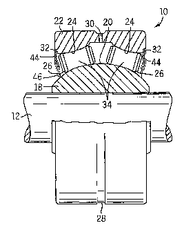
Illustrated in Fig. 1 is a roller bearing apparatus which embodies the
invention and
which is shown supporting a rotating or oscillating shaft 12: In the
particular embodiment
illustrated in the drawings, the bearing apparatus 10 is an angular contact
internally self-
aligning bearin8-
The bearing apparatus 10 comprises an annular inner race or ring member 18
through which the shaf112 extends. The inner ring member 18 includes a arcuate
outer
surface forming an inner bearing race surface 20. The inner race surface 20 is
preferably
substantially spheroidal and has (Fig. 2) a radius of murvature k. If desired,
collais (not
shown) can be secnred on the opposite ends of the inner ring member 18 to
provide
misalignment stops and a surface for a seal to engage. A bearing apparatus
including
suitable collars is illustrated in aforementioned U.S. Pat. No. 2,767,037.
The roller bearing 10 also comprises an annular outer race or ring member 22
encircling the inner ring member 18. The outer ring member 22 includes at
least one
radially inwardly facing outer race surface. In the illustrated arrangement,
the outer ring
member 22 includes a pair of axially oppositely inclined arcuate outer race
surfaces 24
each opposing the inner race surface 20 to provide a pair of raceway spaces
26. The outer
race surfaces 24 are of generally convex curvature and each has (Fig. 2) a
radius of
curvature R, that is preferably substantially constant The value of radius of
mwvatare Rõ
for both outer race surFaces 24 is preferably the same (within manuFacturing
tolerances)
and, in the illustrated embodiment, is approxunately equal to radius of
mwvahue R.
-5-
CA 02420474 2003-02-26
WO 02/21007 PCT/US01/25360
To facilitate periodic lubrication of the bearing apparatus 10, an annular
groove 28
is provided on the outer circumferential side of the outer ring member 22 and
a hole 30
communicates between the groove 28 and the interior of the bearing apparatus
10. A
desired lubricant can be injected into the groove 28 by suitable means such as
a grease gun
(not shown), as is described in U.S. Pat. No. 2,767,037. Although an annular
groove is
disclosed, an annular groove for periodic lubrication is not required, and in
certain
applications not preferred. Other means for lubricating the bearing apparatus
can be used if
desired, such as packing the rollers in grease, without departing from the
scope of the
present invention.
The roller bearing 10 also comprises a plurality of rollers 34. In the
illustrated
embodiment, the rollers 34 are arranged in the raceway spaces 26 in oppositely
axially
inclined annular rows. Each row includes up to a full complement of rollers 34
(i.e.,
maximum number of rollers that will fit in a row when no retainer or other
structure
intervenes between adjacent rollers). Since the bearing apparatus 10 is
retainerless, as is
further discussed below, each roller 34 is engageable with the adjacent
rollers on its
opposite sides, as well as with the inner race surface 20 and the associated
one of the outer
race surfaces 24. While the rollers 34 can have various configurations, in the
illustrated
arrangement the rollers are identical (within manufacturing tolerances), and
each roller 34
has (Fig. 2) a longitudinal axis 36 and is symmetric about a plane which is
perpendicular
to the axis 36 and which includes a line 38 at the midpoint of the roller 34.
As shown in Fig. 2, each roller 34 includes a midsection 40 with an arcuate
outer
surface having a concave longitudinal profile with a radius of curvature R,
that is
preferably constant. In the particular embodiment illustrated in the drawings,
radius of
curvature Rr is greater than each of the radii R. and Ro. Each roller 34 also
has opposite
end portions 42 that are substantially cylindrical.
Since the bearing apparatus 10 does not include a retainer, guide ring,
collars, etc.,
the inner race surface 20 and the outer race surfaces 24 serve as the sole
means for holding
and positioning the rollers 34 of each row within the corresponding raceway
space 26.
Additionally, since the inner race surface 20 is spheroidal and R, is less
than Rr, sliding
movement between the rollers 34 and the inner race surface 20 is substantially
eliminated
and pivotal movement of each roller 34 about its midpoint line 38 is at most
minimally
-6-
CA 02420474 2003-02-26
WO 02/21007 PCT/US01/25360
interfered with by the inner race surface 20. Therefore, such pivotal movement
(i.e.,
skewing) is controlled substantially entirely by contact between the rollers
34 and the
associated outer race surfaces 24.
In particular, under no load conditions (FIG. 3), substantially point contact
exists
between each of the rollers 34 and the associated outer race surface 24. Any
pivotal
movement by a roller 34 about its midpoint line 38 (skewing) results in
development of a
line of contact (see FIG. 2) between that roller and the associated outer race
surface 24
which inhibits further skewing. If roller skew continues to increase the line
of contact
eventually reaches the end portions 42 of the hourglass-shaped rollers, which
ends restrict
any further skewing. Under loaded conditions, contact between the roller 34
and the
associated outer race surface 24 and the inner race surface 20 is extended
axially
outwardly from the mid-point of the roller 34 due to material deflection as
well as roller
skewing. Although the effects of that relationship are not fully understood,
it has been
observed that substantial indexing or precessing of the rollers 34 is achieved
when the
bearing apparatus 10 is used in oscillatory applications. Additionally, tests
have indicated
substantial increases in load rating and bearing life as measured by cycles to
failure
relative to prior art bearings including retainers, this being primarily due
to the increased
number of rollers 34 over which the load is distributed.
In one particular embodiment of the invention having the concave rollers, for
example, a full complement of sixteen rollers 34 each having a diameter (in
end view) of
about 0.4 inch are used in each row, although fewer rollers 34 could be used
to
accommodate additional lubricant, if desired. In that embodiment, R, is about
1.536 inches
and about 0.0 15 inch greater than each of R. and Ro (i.e., about 1%
osculation or difference
in curvature between the rollers and the inner and outer race surfaces). While
optimum
osculation values are not known, 1% osculation in combination with the
tightened radial
internal clearance is effective to achieve consistent roller control and
guidance, and
Applicant believes that osculation values up to about 4% may be employed.
Applicant has discovered that by maintaining a radial internal clearance of no
more
than 0.002 inches between each axially inclined roller 34 and the inner and
outer race
surfaces 20, 24, the cooperation of the rollers 34 with the outer race
surfaces 24 controls
the roller 34 skew to consistently precess the rollers 34 in an oscillatory
operation. The
-7-
CA 02420474 2003-02-26
WO 02/21007 PCT/US01/25360
radial internal clearance B is shown in Fig. 4 (not to scale), and defmed as
the difference
between the radial height A of the raceway space 26 between the inner and
outer race
surfaces 20, 24 surfaces and the roller radius C. In the embodiment including
concave
rollers 34 which have a varying radius along the longitudinal length of the
roller 34, the
radial internal clearance B must be maintained only at the midpoint 40 of each
roller 34.
Providing a bearing having tighter tolerances than a 0.002 inch radial
internal clearance
requires greater precision in manufacturing which increases the bearing
manufacturing
costs, and is therefore taught away from in the prior art and not obvious.
Moreover, absent
Applicant's disclosure, reducing the radial internal clearance to provide
consistent
precessing is heretofore unknown.
Of course, as the radial internal clearance B approaches zero, the rollers 34
can
bind between the race surfaces 20, 24, and cause the bearing apparatus 10 to
freeze up.
However, Applicant has successfully demonstrated consistent precessing in a
bearing
apparatus 10 having a non-binding radial internal clearance B of no more than
0.002
inches. Moreover, Applicant has successfully demonstrated consistent
precessing in two
different bearing apparatuses having a radial internal clearance B of
approximately 0.0016
inches and .0005 inches, respectively. Furthermore Applicant believes that a
bearing
apparatus 10 having a radial internal clearance B less than 0.0005 inches
which does not
cause the rollers 34 to bind will continue to consistently precess.
While in the illustrated embodiment the rollers 34 are hourglass-shaped, the
outer
race surfaces 24 are convex and the inner race surface is spheroidal, in other
arrangements
the bearing apparatus 10 can have different configurations. For example, a
bearing
apparatus in accordance with the invention can be an annular row of axially
inclined
straight (shown in Figs. 5-9) or tapered (shown in Figs. 10-13) rollers 34A-I
and the inner
and outer race surfaces 20A-I, 24A-I could each be axially inclined linear
surfaces to
accommodate the rollers 34A-I and to hold those rollers 34A-I in position with
out the use
of a retainer, guide ring, or the like. Moreover, a bearing apparatus 10 in
accordance with
the invention can have axially outwardly inclined rollers (shown in Figs. 1,
6, 8) or axially
inwardly inclined rollers (shown in Figs. 7, 9, 11, and 13). In addition,
although two
annular rows of outwardly axially inclined rollers 34 are disclosed in Fig. 1,
the bearing
-8-
CA 02420474 2003-02-26
WO 02/21007 PCT/US01/25360
apparatus 10 can have one or more annular rows, and the rows can be inwardly
axially
inclined without departing from the scope of the present invention.
The bearing apparatus 10 also includes means for containing lubricant and for
preventing contaminants from entering the raceway spaces 26. In the
illustrated
arrangement such means includes annular shield members 44 each seated in one
of the
notches 32, and an annular seal member 46 mounted in each of the shield
members 44.
Although shield members 44 having seal members are disclosed, they are not
required to
practice the invention.
Advantageously, the bearing apparatus 10 includes nothing to guide or position
the
rollers 34 and to control roller skewing other than the primary inner an outer
race surfaces
and 24 (i.e., the bearing apparatus 10 is "retainerless"). Thus, the bearing
apparatus 10
avoids the cost associated with retainers, guide rings, collars, and the like.
Further, the
bearing apparatus 10 avoids the use of internal corners associated with the
primary race
surfaces which is an advantage particulate contamination. The bearing
apparatus 10 also
15 includes an increased number of rollers 34 and/or additional lubricant to
improve
performance, and has the ability to precess or index.
While there has been shown and described what are at present considered the
preferred embodiments of the invention, it will be obvious to those skilled in
the art that
various changes and modifications can be made therein without departing from
the scope
20 of the invention defined by the appended claims.
-9-