Language selection

Search

Patent 2420563 Summary

Third-party information liability

Some of the information on this Web page has been provided by external sources. The Government of Canada is not responsible for the accuracy, reliability or currency of the information supplied by external sources. Users wishing to rely upon this information should consult directly with the source of the information. Content provided by external sources is not subject to official languages, privacy and accessibility requirements.

Claims and Abstract availability

Any discrepancies in the text and image of the Claims and Abstract are due to differing posting times. Text of the Claims and Abstract are posted:

  • At the time the application is open to public inspection;
  • At the time of issue of the patent (grant).
(12) Patent: (11) CA 2420563
(54) English Title: DIALYSIS MACHINE BLOOD CIRCULATING CIRCUIT FITTING
(54) French Title: ACCESSOIRE DE CIRCUIT DE CIRCULATION DU SANG D'UNE MACHINE A DIALYSE
Status: Expired and beyond the Period of Reversal
Bibliographic Data
(51) International Patent Classification (IPC):
  • A61M 1/16 (2006.01)
  • A61M 1/36 (2006.01)
  • G01N 21/05 (2006.01)
(72) Inventors :
  • DELNEVO, ANNALISA (Italy)
(73) Owners :
  • GAMBRO DASCO S.P.A.
(71) Applicants :
  • GAMBRO DASCO S.P.A. (Italy)
(74) Agent: ROBIC AGENCE PI S.E.C./ROBIC IP AGENCY LP
(74) Associate agent:
(45) Issued: 2009-09-22
(86) PCT Filing Date: 2002-03-04
(87) Open to Public Inspection: 2002-09-12
Examination requested: 2006-12-22
Availability of licence: N/A
Dedicated to the Public: N/A
(25) Language of filing: English

Patent Cooperation Treaty (PCT): Yes
(86) PCT Filing Number: PCT/IT2002/000131
(87) International Publication Number: WO 2002070041
(85) National Entry: 2003-02-21

(30) Application Priority Data:
Application No. Country/Territory Date
TO2001U000037 (Italy) 2001-03-02

Abstracts

English Abstract


A fitting (1) for a blood circulating circuit (4) of a dialysis machine has a
first ans a second mouth (8, 9) for connecting the fitting (1) to a first ans
a second portion (2, 3) of the blood circulating circuit (4) respectively; the
fitting (1) defining a third portion (10) of the blood circulating circuit (4)
by means of a tuby (6) by which to determine the absorption of electromagnetic
waves by the blood, and by means of a chamber (7) having a wall (15) movable
as a function of the pressure of the blood.


French Abstract

L'invention concerne un accessoire (1) de circuit (4) de circulation du sang d'une machine à dialyse, équipé d'une première et d'une seconde bouche (8, 9) permettant de connecter respectivement l'accessoire (1) à une première et à une deuxième partie (2, 3) du circuit (4) de circulation du sang. L'accessoire (1) définit une troisième partie (10) du circuit (4) de circulation du sang au moyen d'un tube (6) permettant de déterminer l'absorption d'ondes électromagnétiques par le sang, et au moyen d'une chambre (7) possédant une paroi (15) amovible en fonction de la pression du sang.

Claims

Note: Claims are shown in the official language in which they were submitted.

7
WHAT IS CLAIMED IS:
1. A fitting for a blood circulating circuit of a dialysis machine, the
fitting comprising:
a first and a second mouth for connecting the fitting to a first and a
second portion of the blood circulating circuit, respectively; said fitting
defining a
third portion of said blood circulating circuit;
a tube configured to determine the absorption of electromagnetic
waves by the blood flowing through said fitting, said tube being made of rigid
and transparent material; and
a chamber having an elastic membrane movable as a function of
the pressure of the blood flowing through said fitting; said chamber
comprising a
cup formed in one piece with said tube; said chamber comprising a cover for
gripping said elastic membrane between said cup and said cover; said cover
having a hole for access to said elastic membrane.
2. A fitting according to claim 1, wherein said first and second mouth,
said cup, and said cover are made of rigid material.
3. A fitting according to claim 1, wherein said first and second mouth,
said cup, and said cover are made of transparent material.
4. A fitting according to claim 1, wherein said tube extends along an
axis said chamber being substantially cylindrical and having a second axis
crosswise to said first axis.
5. A fitting according to claim 4, comprising a gripping member
located on the opposite side of said first axis with respect to said cover.

8
6. A fitting according to claim 1, wherein said tube has a first diameter
said chamber having a second diameter substantially larger than said first
diameter.
7. A fitting according to claim 1, wherein said first and second mouth,
said cup, and said tube are formed in one piece.
8. A measuring device comprising:
a blood circulating circuit comprising a first, a second, and a third
portion; said third portion being defined by a fitting comprising a first and
a
second mouth for connecting the fitting to said first and second portions
respectively; said fitting comprising a tube configured to determine the
absorption of electromagnetic waves by the blood flowing through said blood
circulating circuit, said tube being made of rigid and transparent material;
the
fitting comprising a chamber having an elastic membrane movable as a function
of the pressure of the blood flowing through said blood circulating circuit;
said
chamber comprising a cup formed in one piece with said tube; said chamber
comprising a cover for gripping said elastic membrane between said cup and
said cover;
a seat for housing said fitting, said seat being the same shape as
said fitting so as to define an unequivocal position of said fitting with
respect to
said measuring device when said fitting is housed in said seat;
a pressure sensor having a first interface cooperating with said
chamber, said first interface being housed in said seat; and
a sensor configured to detect electromagnetic wave absorption,
said absorption sensor having a second interface cooperating with said tube,
said second interface being housed in said seat.
9. A measuring device according to claim 8, wherein said second
interface surrounds said tube.

9
10. A measuring device according to claim 8, wherein said first
interface engages a hole in said cover.

Description

Note: Descriptions are shown in the official language in which they were submitted.


CA 02420563 2003-02-21
WO 02/070041 PCT/IT02/00131
1
DIALYSIS MACHINE BLOOD CIRCULATING CIRCUIT FITTING
TECHNICAL FIELD
The present invention relates to a dialysis machine
circuit fitting.
BACKGROUND ART
Known dialysis machines normally comprise a blood
circulating circuit connected, in use, to the patient's
circulatory system; a treatment fluid circulating
circuit; and a filter, through which the blood
circulating circuit feeds the blood, and the treatment
fluid circulating circuit feeds the treatment fluid. The
filter comprises a semipermeable membrane for separating,
in use, the treatment fluid from the blood, so that ions
are exchanged between the treatment fluid and the blood,
and part of the plasma in the blood is transferred
through the membrane. The blood circulating circuit
comprises an arterial branch upstream from the filter,
and a venous branch downstream from the filter, and the
machine comprises a peristaltic pump located along the
arterial branch to feed the patient's blood to the
filter. The blood circulating circuit and second the

CA 02420563 2008-05-30
2
treatment fluid circulating circuit are made of
transparent, flexible material, such as PVC, which
ensures sterility of the circuits. The flexibility of the
circuits simplifies packaging and enables flow to be cut
off by simply constricting a portion of the circuit,
while transparency enables visual monitoring of liquid
flow in the circuit.
During the dialysis treatment itself, certain
physical characteristics of the blood along the first
circuit are determined non-invasively to monitor
treatment and possibly also adjust dialysis parameters.
This is normally done by means of pressure sensors and
sensors for detecting the absorption of electromagnetic
waves by the blood. Such sensors are provided on the
dialysis machine and are connected to specific points
along the first circuit, which is used for one dialysis
treatment only and then disposed of as controlled waste.
DISCLOSURE OF THE INVENTION
It is an object of the present invention to provide
a circuit fitting enabling troublefree, non-invasive
monitoring of physical characteristics of the blood
during dialysis.
According to the present invention, there is provided a fitting for a
blood circulating circuit of a dialysis machine, the fitting comprising:
a first and a second mouth for connecting the fitting to a first
and a second portion of the blood circulating circuit, respectively; said
fitting
defining a third portion of said blood circulating circuit;

CA 02420563 2008-05-30
3
a tube configured to determine the absorption of
electromagnetic waves by the blood flowing through said fitting, said tube
being made of rigid and transparent material; and
a chamber having an elastic membrane movable as a function
of the pressure of the blood flowing through said fitting; said chamber
comprising a cup formed in one piece with said tube; said chamber
comprising a cover for gripping said elastic membrane between said cup
and said cover; said cover having a hole for access to said elastic
membrane.
According to the present invention, there is also provided a
measuring device comprising:
a blood circulating circuit comprising a first, a second, and a
third portion; said third portion being defined by a fitting comprising a
first
and a second mouth for connecting the fitting to said first and second
portions respectively; said fitting comprising a tube configured to determine
the absorption of electromagnetic waves by the blood flowing through said
blood circulating circuit, said tube being made of rigid and transparent
material; the fitting comprising a chamber having an elastic membrane
movable as a function of the pressure of the blood flowing through said
blood circulating circuit; said chamber comprising a cup formed in one
piece with said tube; said chamber comprising a cover for gripping said
elastic membrane between said cup and said cover;
a seat for housing said fitting, said seat being the same shape
as said fitting so as to define an unequivocal position of said fitting with
respect to said measuring device when said fitting is housed in said seat;
a pressure sensor having a first interface cooperating with
said chamber, said first interface being housed in said seat; and
a sensor configured to detect electromagnetic wave
absorption, said absorption sensor having a second interface cooperating
with said tube, said second interface being housed in said seat.

CA 02420563 2008-05-30
3a
BRIEF DESCRIPTION OF THE DRAWINGS
A non-limiting embodiment of the present invention
will be described by way of example with reference to the
accompanying drawings, in which:
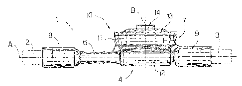
Figure 1 shows a side view of a fitting in
accordance with the present invention;
Figure 2 shows a plan view of the Figure 1 fitting;
Figure 3 shows a schematic front view, with parts
removed for clarity, of a measuring device in accordance
with the present invention;
Figure 4 shows a side view of a variation of the
Figure 1 fitting.
BEST MODE FOR CARRYING OUT THE INVENTION
Number 1 in Figures 1 and 2 indicates a fitting
located between two portions 2 and 3 of a blood

CA 02420563 2003-02-21
WO 02/070041 PCT/IT02/00131
4
circulating circuit 4 of a dialysis machine (not shown)
Fitting 1 is designed for connection to a measuring
device 5 shown in Figure 3, and comprises a tube 6
extending along an axis A; and a chamber 7, which is
adjacent to and integral with tube 6, is located
substantially on one side of axis A, and is substantially
cylindrical with an axis B perpendicular to axis A.
Fitting 1 comprises a mouth 8 for connection to portion
2; and a mouth 9 for connection to portion 3.
In other words, fitting 1 defines a portion 10 of
circuit 4 extending between portions 2 and 3, which are
made of transparent, flexible material, normally PVC.
Tube 6 and chamber 7 communicate directly to allow the
blood to flow, in use, along fitting 1.
With reference to Figure 2, tube 6 has a diameter
Dl, while chamber 7, viewed from above, is circular with
a diameter D2 larger than diameter Dl, and comprises a
cup 11 communicating on one side with tube 6 and on the
opposite side with mouth 9. Cup 11 has a channel-shaped
bottom 12.extending along axis A and connected to tube 6
and to mouth 9. Chamber 7 also comprises a cover 13 with
a central hole 14; and an elastic membrane 15 gripped
between cup 11 and cover 13 to close cup 11. Cup 11, tube
6, and mouths 8 and 9 are formed in one piece of rigid,
, transparent material, which is connected to membrane 15
and cover 13.
Cover 13 is made of the same material as tube 6 and
cup 11, while membrane 15 is made of elastic material so

CA 02420563 2003-02-21
WO 02/070041 PCT/IT02/00131
as to flex alongside variations in the pressure of the
blood.
Tube 6, being used to measure the absorption of
electromagnetic waves, which are affected greatly, for
5 example, by the diameter Dl and the thickness of tube 6,
is made to conform as closely as possible to nominal
dimensions.
With reference to Figure 3, the measuring device 5
is integral with the machine (not shown), and has a seat
16 defined by a recess 17 formed in the body 18 of device
5. Recess 17 has a contour substantially identical with
that of fitting 1 viewed from above, and is deep enough
to house fitting 1 in seat 16 with cover 13 facing seat
16. Device 5 comprises two sensors having respective
interfaces 19 and 20 housed in seat 16 and co-operating
with fitting 1. More specifically, interface 19 forms
part of a pressure sensor (not shown), and co-operates
with membrane 15 to determine deformation of membrane 15
and enable the pressure sensor to generate a signal
related to the pressure of the blood flowing through
fitting 1.
Interface 20 forms part of a sensor for determining
the absorption of electromagnetic waves by the blood
along tube 6, and comprises electromagnetic wave emitters
25, and detectors.
Seat 16 is defined by a groove for housing tube 6
and partly housing circuit 4; and by- an opening
negatively reproducing the shape of chamber 7. Seat 16 is

CA 02420563 2003-02-21
WO 02/070041 PCT/IT02/00131
6
shaped to provide for foolproof connection of fitting 1
and measuring device 5, so that interface 19 fits
accurately inside hole 14, and interface 20 accurately
about tube 6.
In actual use, when circuit 4 is connected in known
manner to the dialysis machine, fitting 1 is inserted
inside seat 16 and fixed to measuring device 5. During
dialysis treatment, the blood flows through fitting 1 and
deforms membrane 15, which is detected by interface 19
inserted inside hole 14. At the same time,
electromagnetic wave absorption by the blood flowing
through fitting 1 is deteCted by interface 20.
In the Figure 4 variation, fitting 1 comprises a
gripping member 21, which is connected to tube 6 at
channel 12 of chamber 7, is located on the opposite side
of axis A to cover 13, is arc-shaped, and is formed in
one piece with tube 6 and cup 11.
Gripping member 21 provides for further simplifying
insertion and removal of the fitting 1 inside and from
seat 16.

Representative Drawing
A single figure which represents the drawing illustrating the invention.
Administrative Status

2024-08-01:As part of the Next Generation Patents (NGP) transition, the Canadian Patents Database (CPD) now contains a more detailed Event History, which replicates the Event Log of our new back-office solution.

Please note that "Inactive:" events refers to events no longer in use in our new back-office solution.

For a clearer understanding of the status of the application/patent presented on this page, the site Disclaimer , as well as the definitions for Patent , Event History , Maintenance Fee  and Payment History  should be consulted.

Event History

Description Date
Time Limit for Reversal Expired 2021-09-07
Letter Sent 2021-03-04
Letter Sent 2020-09-04
Letter Sent 2020-03-04
Common Representative Appointed 2019-10-30
Change of Address or Method of Correspondence Request Received 2018-12-04
Inactive: Correspondence - MF 2010-08-10
Grant by Issuance 2009-09-22
Inactive: Cover page published 2009-09-21
Pre-grant 2009-06-23
Inactive: Final fee received 2009-06-23
Notice of Allowance is Issued 2009-03-05
Letter Sent 2009-03-05
Inactive: Approved for allowance (AFA) 2009-02-26
Amendment Received - Voluntary Amendment 2008-05-30
Inactive: S.30(2) Rules - Examiner requisition 2008-01-17
Letter Sent 2007-01-24
Request for Examination Received 2006-12-22
Request for Examination Requirements Determined Compliant 2006-12-22
All Requirements for Examination Determined Compliant 2006-12-22
Inactive: IPC from MCD 2006-03-12
Inactive: Cover page published 2003-04-23
Letter Sent 2003-04-17
Inactive: Notice - National entry - No RFE 2003-04-17
Application Received - PCT 2003-03-26
National Entry Requirements Determined Compliant 2003-02-21
Application Published (Open to Public Inspection) 2002-09-12

Abandonment History

There is no abandonment history.

Maintenance Fee

The last payment was received on 2008-12-16

Note : If the full payment has not been received on or before the date indicated, a further fee may be required which may be one of the following

  • the reinstatement fee;
  • the late payment fee; or
  • additional fee to reverse deemed expiry.

Please refer to the CIPO Patent Fees web page to see all current fee amounts.

Owners on Record

Note: Records showing the ownership history in alphabetical order.

Current Owners on Record
GAMBRO DASCO S.P.A.
Past Owners on Record
ANNALISA DELNEVO
Past Owners that do not appear in the "Owners on Record" listing will appear in other documentation within the application.
Documents

To view selected files, please enter reCAPTCHA code :


To view images, click a link in the Document Description column. To download the documents, select one or more checkboxes in the first column and then click the "Download Selected in PDF format (Zip Archive)" or the "Download Selected as Single PDF" button.

List of published and non-published patent-specific documents on the CPD .

If you have any difficulty accessing content, you can call the Client Service Centre at 1-866-997-1936 or send them an e-mail at CIPO Client Service Centre.


Document
Description 
Date
(yyyy-mm-dd) 
Number of pages   Size of Image (KB) 
Abstract 2003-02-21 1 60
Description 2003-02-21 6 225
Claims 2003-02-21 3 100
Representative drawing 2003-02-21 1 12
Drawings 2003-02-21 2 64
Cover Page 2003-04-23 1 41
Description 2008-05-30 7 246
Claims 2008-05-30 3 79
Representative drawing 2009-08-28 1 12
Cover Page 2009-08-28 1 43
Notice of National Entry 2003-04-17 1 189
Courtesy - Certificate of registration (related document(s)) 2003-04-17 1 107
Reminder of maintenance fee due 2003-11-05 1 106
Reminder - Request for Examination 2006-11-07 1 118
Acknowledgement of Request for Examination 2007-01-24 1 189
Commissioner's Notice - Application Found Allowable 2009-03-05 1 162
Commissioner's Notice - Maintenance Fee for a Patent Not Paid 2020-04-15 1 545
Courtesy - Patent Term Deemed Expired 2020-09-25 1 548
Commissioner's Notice - Maintenance Fee for a Patent Not Paid 2021-04-22 1 535
PCT 2003-02-21 2 67
Correspondence 2009-06-23 2 55
Correspondence 2010-08-10 1 44