Note: Descriptions are shown in the official language in which they were submitted.
CA 02420644 2011-06-13
RIGID VACUUM TIP
BACKGROUND OF THE INVENTION
1. Field of the Invention
The invention relates to a transfer tip useful in handling injection molded
ophthalmic lens molds, and to a system and a process employing said transfer
tip. The
invention is particularly suited for use with high speed, vacuum and air
pressure assisted
robots that remove still-hot (hence deformable) soft contact lens mold halves
from their
injection molds, and transfer them to a production line pallet conveyor system
for further
processing. The transfer tip has a body portion of a substantially rigid
material. In one
embodiment, the transfer tip of the invention has a working end that has an
outer surface
that is complementary to the shape of the lens mold half being handled, this
being either a
convex or concave shape. In practice, this embodiment of the invention
requires less
applied vacuum and evacuation volume, for example, to achieve part pick up and
transfer
than designs known heretofore. This in turn permits faster or reduced cycling
time with
increased production and more judicious use of resources. In addition, a
reduction in
pressure needed to handle the hot lens molds, as obtained by the invention,
also means
the molds are exposed to less force. This means less deformation of the mold
occurs.
This reduction in deformation is further supplemented by the substantially
rigid nature of
the transfer tip, which rigidity forestalls deformation of the transfer tip
itself under the
forces applied.
2. Description of the Prior Art
Current manufacturing protocols for soft contact lenses call for the curing of
an
appropriate monomer mixture between front and back mold halves. The mold
halves are
typically formed by injection molding suitable plastic materials, such as
polystyrene, into
CA 02420644 2011-06-13
a molding machine comprised of two opposing elements which interface to form
the
mold halves. One element has an array of regularly spaced concave recesses
whereas the
opposing element has a corresponding array of convex protuberances. When
mated, the
concave recesses and convex protuberances define therebetween a shaped volume
in
which the lens mold halves are produced. In operation, the opposing elements
come
together and molten polymer (e.g. polystyrene) is injected into the shaped
volumes
between the surfaces of the opposing elements. The mold halves are held for a
time
sufficient to set their shapes. Once sufficiently set, the opposing elements
separate and
the mold halves are removed.
Generally, the Back Curve (BC) mold halves provide the convex optical mold
surface which shapes the portion of the contact lens that contacts the eye.
The Front
Curve (FC) mold halves provide the concave surface that molds the front face
of the
contact lens. For purposes of maintaining optimal optical integrity, the
molding machine
that produces the Back Curve mold sections is designed so that upon
separation, the non-
optically relevant, concave surfaces of the mold halves are exposed, the
convex surfaces
remaining within the concave recesses. While the molding machine that produces
the
Front Curve mold sections is nearly identical in all functional respects to
the Back Curve
molding machine, it operates such that when its opposing elements separate,
the Front
Curve optically relevant mold sections remain in contact with the convex
protuberances.
A single molding machine can be used to make Back Curve and Front Curve mold
sections simultaneously. Molding machines and robots for which this invention
are
useful are disclosed in Lust et al, "Mold and Molding System for Making
Ophthalmic
Devices", US Patent 6,592,356; Parnell et al, "In-lay Station with Alignment
Assemblies and Transfer Tubes", US Patent 6,708,397 and US Patent 5,545,366.
In production lines, removal of the mold halves, be they Front or Back Curves,
is
ordinarily accomplished through the use of vacuum-assisted robots.
Industrially, these
robots typically employ, at the working end that contacts the mold halves,
soft flexible
materials, such as silicones and rubbers, in the form of variously shaped end
effectors,
suction cups, tips, pads and the like. By convention, soft flexible materials
have been
employed because, in a high speed production line, the mold halves are removed
when
2
CA 02420644 2003-02-28
their shape is set, not necessarily when they are cool. Because they are still
relatively
hot, soft flexible materials have been used in an effort to minimize damage to
the lens
molds, which in their heated state are still pliant and deformable. Damage to
the lens
molds in this regard can adversely affect, in turn, the contact lenses
ultimately cast in said
molds. To further forestall damage, it is common to provide a handling means,
for
example, a flange, somewhere on a non-critical portion of the lens mold, thus
enabling
the robotic transfer tip to contact only the flange or other handling means,
hence leaving
the optically sensitive area of the mold, where the contact lens is formed,
untouched.
FIGURE 1 illustrates a prior art practice. FIGURE 1 is a side view showing
transfer tip 10, made of a soft, flexible material such as silicone rubber,
which tip is
cylindrical in shape and open at the pickup end, defined by annular rim 14. As
seen in
FIGURE 1, the annular rim 14 of tip 10 contacts the injection molded lens mold
11
(depicted in FIGURE 1 as a Back Curve) at flange 15 which is provided for this
purpose.
Transfer tip 10 is connected via aperture 12 to a vacuum source which, when
actuated,
enables pickup of mold 11. Also as seen in FIGURE 1, the interior of
cylindrical tip 10
has a volume 13. This must be sufficiently evacuated by the vacuum source for
pickup to
occur. In a typical design of this type, transfer tip 10 can be about 18mm in
diameter and
about 15mm high (dimensions are approximate). The applied vacuum typically
necessary to effectuate pickup of mold I 1 is thus about 0.8 bar (11 psi). The
volume of
gas 13 thus needed to be evacuated under these circumstances is approximately
3 ml.
The amount of time it takes to evacuate this volume of gas affects the cycle
time of the
production line; that is, the time it takes a robotic transfer device to
remove a lens mold
half from a first location, e.g. from its injection molding machine, transfer
it to a second
location, e.g. a conveyor pallet, and return to the first location to repeat
the process.
Although industrial useful, improvements to known practices, as for example
described for and illustrated by FIGURE 1, are desirable. Among other advances
sought
is a reduction in applied forces, such as vacuum or positive gas pressure,
inasmuch as the
mold halves are removed from the molding machine at temperatures where the
plastic is
still pliant. Forces applied to the part at this time can distort the lens
mold, leading to
deformations in radius of curvature for the optically important surface on the
order of
0.04 to 0.06mm (using e.g. the soft cylindrical tip of FIGURE 1), which can
render the
VTN-581 3
CA 02420644 2003-02-28
mold unacceptable for contact lens casting. Minimization of required forces
for part
pickup and/or deposit would therefore improve mold quality. Moreover, it has
been
found that the use of current soft, flexible materials actually abet twisting
of the lens
mold, which itself causes deformation.
SUMMARY OF THE INVENTION
The present invention is directed to a transfer tip and a system and process
for
using same that achieves a reduction in applied forces and a decrease in cycle
time. In
one embodiment, the invention is a transfer tip for handling an injection
molded
ophthalmic lens mold, said lens mold having either a concave (e.g. Back Curve)
or
convex shape (e.g., Front Curve) and having lens mold handling means thereon,
said
transfer tip comprising:
a substantially rigid body portion having a distal end and a proximal end; the
distal end having an outer surface that is complementary to the concave or
convex shape
of the lens mold to be handled, said body portion having sealing means
peripheral to said
outer surface for engagement with said lens mold; and
at least one aperture extending through said body portion from said proximal
end
to said distal end sufficient for flow communication with a source of
differential pressure.
BRIEF DESCRIPTION OF THE DRAWINGS
FIGURE 1 illustrates a prior art transfer tip.
FIGURES 2A and 2B illustrate the top and edge views of a typical Front Curve
lens mold; FIGURES 2C and 2D illustrate the top and edge views of a typical
Back
Curve lens mold.
FIGURE 3A and 3B respectively illustrate top (distal end) and side views of a
transfer tip embodiment of the present invention particularly suited to the
transfer of the
Back Curve of an injection molded ophthalmic lens mold.
FIGURE 4A and 4B respectively illustrate top (distal end) and side views of a
transfer tip embodiment of the present invention particularly suited to the
transfer of the
Front Curve of an injection molded ophthalmic lens mold.
VTN-581 4
CA 02420644 2003-02-28
FIGURE 5A and 5B respectively illustrate top (distal) and side views of a
transfer
tip embodiment of the present invention suited to either Front or Back Curves.
DETAILED DESCRIPTION OF THE INVENTION
The invention pertains to the handling of injection molded ophthalmic lens
molds.
Ophthalmic lenses in this regard include without limitation those fabricated
in such
molds, for example, soft contact and intraocular lenses. The invention is
especially utile
in the context of soft contact lenses, also known as hydrogel lenses. These
lenses are
typically prepared from monomers including but not limited to: hydroxyethyl
methacrylate (HEMA), vinyl pyrrolidone, glycerol methacrylate, methacrylic
acid and
acid esters.
While not constraining the present invention, soft lenses in this regard are
typically prepared by free radical polymerization of monomer mix in lens molds
fabricated as has been described hereinabove. The monomer mix may contain
other
additives as known in the art, e.g. crosslinking and strengthening agents.
Polymerization
is conventionally initiated by thermal means, or is photoinitiated using
either UV or
visible light. In these cases, the plastic lens molds in which polymerization
occurs are
effectively transparent to the photoinitiating light.
Plastics that commonly serve as materials of construction for injection molded
lens molds in this regard are from the family of thermoplastics and can
include without
limitation: polyolefins, such as low-, medium-, and high-density polyethylene,
polypropylene, and copolymers thereof; polystyrene; poly-4-methylpentene;
polyacetal
resins; polyacrylether; polyarylether; sulfones; Nylon 6; Nylon 66; Nylon 11;
thermoplastic polyester and various fluorinated materials such as the
fluorinated ethylene
propylene copolymers and ethylene fluoroethylene copolymers. Polystyrene is
preferred.
FIGURE 2 shows an embodiment of an injection molded ophthalmic lens mold to
which the present invention has especial use, it being understood that other
designs and
styles of lens molds are contemplated as being within the scope of the
inventive practice.
FIGURES 2A and 2B depict a top and side view, respectively, of a Front Curve
lens
mold for a soft contact lens; similarly, FIGURES 2C and 2D depict top and side
views of
VTN-581 5
CA 02420644 2003-02-28
a Back Curve lens mold for soft contact lens. In preferred practices, the lens
molds are
fabricated with handling means thereon. These can be, without limitation,
surfaces or
other appendages that are apart from optically important central surface, such
as for
example a flange extending partly or entirely around the mold. In FIGURE 2, a
preferred
handling means is illustrated as annular flange 21 (Front Curve) and annular
flange 24
(Back Curve). Tabs 22 and 25 may optionally be provided to further facilitate
handling
and positioning.
As indicated previously, and in further regard to FIGURE 2, in a preferred
practice, the molding machine that produces the Back Curve is designed so that
upon
separation of the opposing mold elements, the concave surface 23 of the Back
Curve lens
mold is exposed. Conversely, the molding machine for the Front Curve separates
such
that the convex surface 20 of the Front Curve lens mold is exposed.
The transfer tip of the present invention will now be described with reference
to
the preferred embodiments of same illustrated at FIGURES 3, 4 and 5. The
practices so
illustrated and described hereinafter are especially suitable for use with
lens molds having
shapes similar to those shown in FIGURE 2. It will be appreciated that the
inventive
transfer tip is not limited to these preferred embodiments and that variations
to same are
within the scope and spirit of the invention.
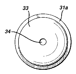
FIGURES 3A and 3B show top and side views, respectively, of a preferred
embodiment of the transfer tip of the present invention useful in handling
lens molds
having a concave shape, such as for example and without limitation, the Back
Curve
illustrated at FIGURES 2C and 2D where, for purposes of the present
discussion, the
concave shape is surface 23. The transfer tip is comprised of body portion 30
having a
distal end (that is, the working end, or end in contact with the lens mold
part that is being
handled) generally at 31 and a proximal end, generally at 32, which proximal
end serves
as the connection to the robotic assembly or other automated transfer device
(not shown)
and to the source of pressure differential such as vacuum means or positive
(gas) pressure
(not shown). The distal end, generally at 31, has an outer surface 33 which is
complementary, in shape, to the concave shape of the lens mold part to be
handled. For
example, outer surface 33 is of a convex shape that is complementary to
concave surface
23 of the Back Curve in FIGURE 2 so as to be as close to form-fitting to
surface 23 (the
VTN-581 6
CA 02420644 2003-02-28
area of non-optically relevant curvature of the lens mold) as practicable
without
impinging on same. The body portion further has a sealing means peripheral to
the
outer surface. In the preferred embodiment of FIGURE 3, the sealing means is
in the
form of annular sealing ring 3 la, which can be in the form of a flange or the
like surface
that is preferably integral with, but can be otherwise constituted as known in
the art to
body portion 30. Preferably, the sealing means on the transfer tip and the
handling
means on the lens mold are both in the same plane; preferably both are flat,
sufficient to
create and maintain a seal (by e.g. vacuum) effective to enable part pickup.
For example,
in the embodiments shown, annular sealing ring 31a is in the same plane as
annular
flange 24 on the Back Curve Figure 2.
Body portion 30, including outer surface 33, is substantially rigid. For
example, it
is of a constitution that will not deform, and will maintain its dimensions
and geometry
under the elevated temperatures present on and about the lens mold as removed
from the
molding machine, and under the pressures of the applied force created between
the
sealing means of the transfer tip and the handling means (e.g. flange) of the
molded part.
The substantially rigid nature of body portion 30 is preferably obtained
through choice of
materials of construction. Generally speaking, any material having a hardness
sufficient
to enable it to be machined or otherwise shaped to have the requisite geometry
and
dimensional tolerances, e.g. flatness and the like, to achieve a workable
seal, without
deformation or distortion of the transfer tip when subjected to the applied
sealing
pressures with the lens mold, and which also has requisite thermal strength
for the
temperatures involved, can be used. This includes a variety of polymeric
materials,
metals, ceramics, cellulosic materials and the like. In a preferred practice,
the material of
construction has a Shore D Hardness of about 58 to about 90; more preferably
about 75 to
about 90; still more preferably about 85 to about 87. Serviceable polymeric
materials
include, without limitation, engineering grade plastics. Self-lubricating
polymeric
materials can be advantageously used to avoid sticking or adhering of the hot
lens mold
to the transfer tip. By way of exemplification only, and without constraining
the scope of
possible materials, preferred polymeric materials include polyacetyls (e.g.
Delrin ,
which is most preferred, having a Shore D Hardness of about 86), polystyrenes,
polypropylenes, polyethylenes, polyetheretherketones (PEEK), polyamides (e.g.
Nylon
VTN-581 7
CA 02420644 2003-02-28
), polyimides, polyamideimides (PAI), polyfluoroethylenes (e.g. Teflon ),
polyetherimides, polyesters, polycarbonates, polyethers, polyetherimides,
polysulfide
polymers, polysulfones, and blends and alloys of the foregoing. Polyacetyls,
such as
Delrin , are preferred. Useable metals include, again by way of example only,
aluminum, stainless steel and like elemental metals and alloys that can be
machined into
the appropriate geometry, dimensional tolerances and sealing flatness.
In another preferred practice, the transfer tip of the invention is machined
entirely
from a unitary block of material, e.g. Delrin , using a lathe or other
suitable means
known in the art.
Also as shown in FIGURE 3, the transfer tip has at least one aperture 34
extending through said body portion 30 sufficient for flow communication with
a source
of differential pressure. The aperture can be one or more holes or bores of
sufficient size
drilled through the transfer tip. In a preferred embodiment, a single aperture
through the
center of the transfer tip is employed. The source of differential pressure
can include
vacuum or positive (gas) pressure sources as known in the art. For example,
vacuum is
drawn through aperture at the center of the transfer tip to create
differential pressure in
the spatial volume between the transfer tip and the lens mold. As illustrated
in FIGURE
3, the transfer tip preferably has at the proximal end 32 connection means for
connection
to said robotic assembly or other transfer device, such as for example a
threaded portion
35 for conveniently removable connection to same. Other means of connection
known in
the art may also be employed.
FIGURES 4A and 4B show top and side views, respectively, of a preferred
embodiment of a transfer tip of the invention useful in handling lens molds
having a
convex shape, such as for example and without limitation, the Front Curve
illustrated at
FIGURES 2A and 2B, where the convex shape is surface 20. The definitions and
descriptions provided for the embodiment of FIGURE 3 aforesaid apply hereto
unless
otherwise indicated. FIGURE 4B shows a side view of said preferred transfer
tip having
substantially rigid body portion 40 having a distal (working) end generally at
41 and a
proximal (connection) end generally at 42 which end is ultimately connected to
the
robotic assembly or other transfer device and a source of pressure
differential as
hereinbefore described. The distal end, generally at 41, has an outer surface
43 whose
VTN-581 8
CA 02420644 2003-02-28
shape is complementary to the shape of the lens mold; that is, outer surface
43 is concave
whereas the shape of the lens mold, e.g. the Front Curve, is convex. Again, it
is preferred
if the concave outer surface 43 is as close to form-fitting the convex Front
Curve surface
20 as practicable without impingement. Substantially rigid body portion 40
also has
thereon a sealing means in the form of an annular sealing ring 41a, which in
the
embodiment of FIGURE 4 is in the form of the rim or edge 41 a of the body
portion 40,
flat and in the same plane as e.g. flange 21 on Front Curve FIGURE 2A and 2B.
Body
portion 40 further has at least one aperture 44 extending therethrough from
said proximal
end 42 to said distal end 41 for flow communication with a source of
differential
pressure. As depicted, it is preferred if proximal end 42 further comprises
connection
means for attachment to said robotic assembly or other transfer device, such
as for
example threaded portion 45.
FIGURES 5A and 5B show top and side views respectively, of yet another
embodiment of a transfer tip of the invention, this particular embodiment
being useful
for handling either Front or Back Curves. Again the definitions and
descriptions
provided for the embodiments of FIGURES 3 and 4 aforesaid apply hereto unless
otherwise indicated. FIGURE 5B shows a side view of said transfer tip having a
distal
(working) end generally at 51 and a proximal end generally at 52 ultimately
connected to
the robotic assembly or other transfer device and source of pressure
differential as
hereinbefore described (connection means not shown in FIGURE 5). Substantially
rigid
body portion 50 has at distal end 51 a sealing means in the form of an annular
sealing
surface 51 a, which in the embodiment of FIGURE 5 is in the form of a rim or
edge 51a of
said body portion. Body portion 50 furthermore has a plurality of apertures 54
extending
from the proximal end 52 to said annular sealing surface 5la. In a preferred
practice, the
plurality of apertures, e.g. holes through said rim 5la to said proximal end
52, are equally
spaced around the circumference of the annular sealing surface. In the
embodiment
shown in FIGURE 5A, six holes, each about 60 apart, are provided. The
equidistant
nature and uniformity in size of the holes in the annular sealing surface 51 a
results in an
equalization and uniformity of forces felt by the lens mold being handled. In
practice,
when the transfer tip of FIGURE 5 is employed to handle a lens mold having a
convex
VTN-581 9
CA 02420644 2003-02-28
shape (e.g. Front Curve), the convex surface of same (e.g. surface 20 of
FIGURE 2) is
situated in void 53, with annular sealing surface 51a engaged with flanged 21.
Alternatively, another embodiment of the invention that is not shown is to
modify
the embodiment shown in FIGURES 5A and 5B to add the convex and concave rigid
shapes 33, and 43 of the embodiments shown in the FIGURES 3A and 3B and
FIGURES
4A and 4B while maintaining the plurality of apertures 54 as shown in FIGURES
5A and
5B. The apertures 34 and 44 as shown in FIGURES 3A and 3B and FIGURES 4A and
4B are optional.
In the most preferred embodiments, the transfer tips of FIGURES 3, 4 and 5 are
machined from a unitary block of polyacetyl, such as Delrin , having a Shore
D
Hardness of about 86. In the practice of the invention using the most
preferred
embodiments of FIGURES 3 and 4, radial distortions of the lens molds being so
handled
of about 0.01 to 0.02mm were observed. Without being bound to any theory, it
is
believed said reductions were due partly because less evacuation time and less
vacuum
was required, and partly to the fact that the lens molds could be removed from
the
injection molding machines at a hotter temperature using the transfer tip of
the invention
as opposed to prior art tips.
VTN-581 10