Language selection

Search

Patent 2420692 Summary

Third-party information liability

Some of the information on this Web page has been provided by external sources. The Government of Canada is not responsible for the accuracy, reliability or currency of the information supplied by external sources. Users wishing to rely upon this information should consult directly with the source of the information. Content provided by external sources is not subject to official languages, privacy and accessibility requirements.

Claims and Abstract availability

Any discrepancies in the text and image of the Claims and Abstract are due to differing posting times. Text of the Claims and Abstract are posted:

  • At the time the application is open to public inspection;
  • At the time of issue of the patent (grant).
(12) Patent Application: (11) CA 2420692
(54) English Title: GEAR PULLER HAVING OUTWARDLY FORCED JAWS
(54) French Title: EXTRACTEUR DE PIGNONS COMPRENANT DES MACHOIRES A PRESSION FORCEE VERS L'EXTERIEUR
Status: Deemed Abandoned and Beyond the Period of Reinstatement - Pending Response to Notice of Disregarded Communication
Bibliographic Data
(51) International Patent Classification (IPC):
  • B23P 19/04 (2006.01)
  • B25B 27/00 (2006.01)
  • B25B 27/06 (2006.01)
  • B25B 33/00 (2006.01)
(72) Inventors :
  • CHIANG, CHEN CHI (Taiwan, Province of China)
(73) Owners :
  • CHEN CHI CHIANG
(71) Applicants :
  • CHEN CHI CHIANG (Taiwan, Province of China)
(74) Agent: BULL, HOUSSER & TUPPER LLP
(74) Associate agent:
(45) Issued:
(22) Filed Date: 2003-03-04
(41) Open to Public Inspection: 2003-09-12
Availability of licence: N/A
Dedicated to the Public: N/A
(25) Language of filing: English

Patent Cooperation Treaty (PCT): No

(30) Application Priority Data:
Application No. Country/Territory Date
10/095,159 (United States of America) 2002-03-12

Abstracts

English Abstract


A gear puller includes a barrel (12) having an orifice (121)
formed in one end, two jaws (11) received in the barrel (12) and
each having one end extended outward through the orifice (121) of
the barrel (12), and each having a peripheral flange (112) for
engaging into a gear or bearing (60) to be pulled. An actuator rod
(21) may be engaged into the jaws (11), to move the jaws (11) away
from each other to solidly engage with the gear or bearing (60 to be
pulled. A shank (31) is secured to the barrel (12) and has a block
(343). A hammer (33) is slidably engaged on the shank (31) and
movable to strike onto the block (343), for forcing the jaws (11) to
remove the gear or bearing (60) from the object (70).


Claims

Note: Claims are shown in the official language in which they were submitted.

THE EMBODIMENTS OF THE INVENTION IN WHICH AN
EXCLUSIVE PROPERTY OR PRIVILEGE IS CLAIMED ARE
DEFINED AS FOLLOWS:-
1. A gear puller comprising:
a) a barrel including a first end having an orifice formed
therein,
b) at least two jaws received in the barrel, and each including a
first end extended out through the orifice of the barrel, and a flange
extended from the first end thereof to engage into a gear or bearing,
c) a bucket secured to the barrel,
d) a spring received in the bucket and engaged onto the jaws, to
bias the first ends of the jaws out of the orifice of the barrel,
e) means for moving the jaws away from each other to solidly
engage with the bear, and
f) means for forcing the jaws to disengage the bearing from an
object.
2. A gear puller as claimed in claim 1, wherein the jaws each
includes a hole, the moving means includes an actuator rod engaged
into the holes of the jaws to force the jaws away from each other.
3. A gear puller as claimed in claim 2, wherein the forcing
means includes a shank coupled to the rod and having a block, and a
hammer slidably engaged on the shank and movable to strike onto
the block.
4. A gear puller as claimed in claim 3 further comprising an
arm, a hand grip secured to the shank and including an aperture to
receive the arm.
5. A gear puller as claimed in claim 1 further comprising
6

means for biasing the jaws toward each other.
6. A gear puller as claimed in claim 5, wherein the jaws each
includes an outer peripheral recess, the biasing means includes a
retaining ring engaged into the outer peripheral recess of the jaws.
7. A gear puller substantially as herein described with
reference to the accompanying drawings.

Description

Note: Descriptions are shown in the official language in which they were submitted.


CA 02420692 2003-03-04
GEAR PULLER HAVING OUTWARDLY FORCED JAWS
The invention relates to a gear pulley having outwardly forced
j aws to engage into the bearings and t.o remove the bearings from
objects.
Typical gear pulleys comprise a number of jaws movable or
engageable onto the outer peripheral portion of gears or bearings,
for pulling the gears or the bearings from the supporting objects.
However, when the gears or the bearings are deeply received in the
supporting objects, the gear pulleys may no longer be engaged into
the gears or the bearings, such that the gear pulleys may not be used
to pull or to remove the gears or the bearings that are deeply
received in the supporting objects.
It is accordingly an object of the present invention to provide a
gear pulley including outwardly forced jaws to engage into the gears
or the bearings, and to remove the gears or the bearings from inside
of the objects.
SUMMARY OF THE INVENTION
According to the invention there is provided a gear pulley
comprising:-
a barrel including a first end having an orifice formed therein,
at least two jaws received in the barrel, and each including a
first end extended out through the orifice of the barrel, and a flange
extended from the first end thereof to engage into a gear or bearing,
a bucket secured to the barrel,
biasing means including a spring and a collar received in the
bucket and engaged onto the jaws, to bias the first ends of the jaws
out of the orifice of the barrel,

CA 02420692 2003-03-04
means for moving the jaws away from each other to solidly
engage with the bear, and
means for forcing the jaws to disengage the bearing from an
object.
BRIEF DESCRIPTION OF THE DRAWINGS
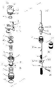
FIG. 1 is a perspective view of a gear pulley;
FIG. 2 is an exploded view of a gear pulley;
FIG. 3 is a partial exploded view of the gear pulley;
FIG. 4 is a partial cross sectional view taken along lines 4-4 of
l0 FIG. l;
FIG. 5 is a partial cross sectional view of the gear pulley;
FIG. 6 is an end view of the jaws of the gear pulley;
FIG. 7 is a plan schematic view illustrating the engagement of
the jaws into the bearing to be removed by the gear pulley;
FIG. 8 is a partial cross sectional view illustrating the
operation of the gear pulley
FIG. 9 is a partial cross sectional view illustrating the
engagement of the jaws into the broken or damaged bearing to be
removed by the gear pulley;
FIG. 10 is a plan schematic view illustrating the other
embodiment of the gear pulley, in which a portion of the jaws has
been cut off; and
FIG. 11 is an end view of the jaws of the gear pulley as shown in
FIG. 10.
DESCRIPTION OF THE PREFERRED EMBODIMENT
Referring to FIGS. 1-5, a gear pulley comprises a hand grip 34
including an aperture 342 to receive an arm 35 which may be used
2

CA 02420692 2003-03-04
for rotating the hand grip 34. The hand grip 34 includes a screw
hole 341, and a block 343 formed on one end. A shank 31 includes
an outer thread 31 I for threading with the screw hole 341 of the
hand grip 34. A quick coupler 32 is attached to the other end of the
hand grip 34. A hammer 33 includes a bore 331 to slidably receive
the shank 31, and may slide along the shank 31 to strike onto the
block 343.
A gearing coupling device 10 includes a barrel 12 having a
chamber 120, and an orifice 121 formed in a peripheral flange 124,
and a space 122 (FIGS. 4, 5) having an inner diameter greater than
that of the chamber 120. Two jaws I I may form a cylinder and each
has hole I I l, a peripheral flange 112 and a peripheral stop 114. One
end of the jaws 11 or the flanges 11'~ are extended out of the barrel
12. The peripheral stops 114 of the jaws I 1 are engaged in the
enlarged space 122 of the barrel 12 for rotatably securing the jaws
11 to the barrel 12.
A retaining ring 40 is engaged around the peripheral recess 113
of the jaws 1 I for biasing the jaws 11 toward each other. The barrel
12 includes an outer thread 126 for threading with an inner thread of
a bucket 13. A washer 41 and a clamping ring 42, and a spring 51
and a collar 52 are engaged onto the jaws 11, for biasing the jaws 11
out of the barrel 12.
An actuator rod 21 is engaged through the collar 52 and the
holes 111 of the jaws 11., for forcing the jaws 11 away from each
other against the retaining ring 40, and for forcing the flanges 112
of the jaws 11 to engage into the inner hole 601 of the gear or
bearing 60 to be pulled (FIGS. 7-9). The jaws 11 include a cut
3

CA 02420692 2003-03-04
portion 116 (FIG. 6), for allowing the flanges 112 to be easily
engaged into the inner hole 601 of the gear or bearing 60. The
actuator rod 21 includes a peripheral wall 20, and two peripheral
grooves 22, 23 formed beside the wall 20. The actuator rod 21 may
engage with the collar 52, and the spring 51, to bias the jaws 11 out
of the barrel 12.
The bucket 13 includes one or more orifices 131 to receive a
ball 53 each, a ferrule 14 is slidably engaged onto the bucket 13,
and a peripheral bulge 141 to force the balls 53 into the groove 22
of the rod 21, for detachably locking the rod 21 to the bucket 13. A
spring S4 is engaged between the ferrule 14 and the bucket 13, to
bias the bulge 141 of the ferrule 14 to force the balls 53 to lock the
rod 21 to the bucket 13. The balls 53 may be disengaged from the
rod 21 when the bulge 141 of the ferrule 14 is disengaged from the
balls 53 by moving the ferrule 14 against the spring 54.
A retaining ring 55 may be engaged into the peripheral slot 132
of the bucket 13, and may be engaged with the ferrule 14, to retain
the ferrule 14 to the bucket 13. The quick coupler 32 of the shank 31
is similar to the ferrule 14 and the balls S3, for detachably securing
the rod 21 to the shank 31.
In operation, the jaws 11 may be engaged into the hole 601 of
the bearing 60, the rod 21 may be engaged into the holes 111 of the
jaws 1 l, to force the flanges 112 of the jaws 11 to solidly engage
with the bearing 60. The hammer 33 may then be moved along the
shank 31 (FIG. 8) to strike onto the block 343, to pull the bearing 60
out of the object 70. The flanges 112 of the jaws 11 may also be
solidly engaged into the damaged outer shell 602 of the bearing 60.
4

CA 02420692 2003-03-04
As shown in FIGS. 10, 11, one or more pairs of jaws 152 rnay
further be provided, and each includes a number of holes 151 to
receive fasteners 16, and a flange 1.52 to engage into the gear or
bearing to be pulled. The jaws 1 SZ each may include a cut portion
154 for allowing the jaws 15 to be easily engaged into the gear or
the bearing to be pulled.
15
25
5

Representative Drawing
A single figure which represents the drawing illustrating the invention.
Administrative Status

2024-08-01:As part of the Next Generation Patents (NGP) transition, the Canadian Patents Database (CPD) now contains a more detailed Event History, which replicates the Event Log of our new back-office solution.

Please note that "Inactive:" events refers to events no longer in use in our new back-office solution.

For a clearer understanding of the status of the application/patent presented on this page, the site Disclaimer , as well as the definitions for Patent , Event History , Maintenance Fee  and Payment History  should be consulted.

Event History

Description Date
Application Not Reinstated by Deadline 2007-03-05
Time Limit for Reversal Expired 2007-03-05
Inactive: IPC from MCD 2006-03-12
Deemed Abandoned - Failure to Respond to Maintenance Fee Notice 2006-03-06
Application Published (Open to Public Inspection) 2003-09-12
Inactive: Cover page published 2003-09-11
Inactive: IPC assigned 2003-05-29
Inactive: First IPC assigned 2003-05-29
Application Received - Regular National 2003-03-27
Filing Requirements Determined Compliant 2003-03-27
Inactive: Filing certificate - No RFE (English) 2003-03-27

Abandonment History

Abandonment Date Reason Reinstatement Date
2006-03-06

Maintenance Fee

The last payment was received on 2005-03-01

Note : If the full payment has not been received on or before the date indicated, a further fee may be required which may be one of the following

  • the reinstatement fee;
  • the late payment fee; or
  • additional fee to reverse deemed expiry.

Please refer to the CIPO Patent Fees web page to see all current fee amounts.

Fee History

Fee Type Anniversary Year Due Date Paid Date
Application fee - small 2003-03-04
MF (application, 2nd anniv.) - small 02 2005-03-04 2005-03-01
Owners on Record

Note: Records showing the ownership history in alphabetical order.

Current Owners on Record
CHEN CHI CHIANG
Past Owners on Record
None
Past Owners that do not appear in the "Owners on Record" listing will appear in other documentation within the application.
Documents

To view selected files, please enter reCAPTCHA code :


To view images, click a link in the Document Description column. To download the documents, select one or more checkboxes in the first column and then click the "Download Selected in PDF format (Zip Archive)" or the "Download Selected as Single PDF" button.

List of published and non-published patent-specific documents on the CPD .

If you have any difficulty accessing content, you can call the Client Service Centre at 1-866-997-1936 or send them an e-mail at CIPO Client Service Centre.


Document
Description 
Date
(yyyy-mm-dd) 
Number of pages   Size of Image (KB) 
Description 2003-03-04 5 185
Claims 2003-03-04 2 50
Abstract 2003-03-04 1 20
Drawings 2003-03-04 7 119
Representative drawing 2003-05-30 1 10
Cover Page 2003-08-19 2 44
Filing Certificate (English) 2003-03-27 1 169
Reminder of maintenance fee due 2004-11-08 1 110
Courtesy - Abandonment Letter (Maintenance Fee) 2006-05-01 1 177
Fees 2005-03-01 2 59