Note: Descriptions are shown in the official language in which they were submitted.
CA 02420797 2003-02-27
APPARATUS FOR SECURING A WORKPIECE
BACKGROUND OF THE INVENTION
This invention relates generally to an apparatus for securing a workpiece and,
more particularly, to a vise having a clutched handle facilitating enhanced
control over
the handles of the vise and accessories capable of being connected to a vise
and used in
conjunction therewith.
The tool industry offers a variety of workholding equipment, such as vises,
for use
with various types of workpieces. One common shortcoming, however, is that the
available workholding apparatus do not offer handles that can account for the
various
space constraints that may exist when working with particularly shaped
workpieces, or in
certain work areas and environments. For example, some workpieces are of such
size and
awkward shape that it is difficult, if not impossible, to efficiently use
traditional vise
handles such as slotted T-shape handles which are typically used for vise
spindle handles
and vise rotation lock handles (or rotation restraint handles). More
particularly, the size
and/or shape of workpieces often interfere with the user's ability to operate
such handles.
Thus, rather than rotating the handle in an efficient one hundred and eighty
or three
hundred and sixty degree rotation, the workpiece may only allow for the handle
to be
rotated in smaller degree increments, increasing the amount of time it takes
to perform the
desired function and/or increasing the amount of difficulty in performing the
desired
function.
In another example, the work space or work environment may itself make it
difficult, if not impossible, to efficiently use traditional vise handles.
More particularly,
some workholding apparatus work areas, such as drill press mounted vises, are
of such
limited space that they hinder the operation of the workholding apparatus and
its handles.
With respect to drill press vises, the table (or bed) of the drill press can
prevent the vise
handle from being operated in a three hundred and sixty degree rotation and
can provide
such little space between the handle gripping surface and the surface of the
drill press
table that the apparatus user has difficulty in obtaining a good grip of the
handle.
Another problem associated with traditional workholding apparatus handles is
that
the handles are not selectively positionable in a variety of different
positions in order to
-1-
CA 02420797 2003-02-27
provide the apparatus user with the ability to freely reposition the handle to
obtain a better
grasp and/or leverage to operate the handle. For example, most slotted T-shape
handles
will not stay in a variety of positions, but rather will slide through the
collar of the handle,
rotate to an alternate position, or both. More particularly, when a user
rotates a slotted T-
shape handle to any angle above the horizontal plane, the handle will fall
back to the
horizontal plane and/or slide through the collar of the slotted T-shape
handle.
In addition, current workholding equipment is not equipped to be used in
connection with alternate accessories. For example, traditional vises are
either used to
clamp a workpiece or provide an anvil surface upon which the workpiece may be
supported. Thus, traditional vises provide only a minimal amount of useful
work and take
up a significant amount of work space.
Accordingly, it has been determined that the need exists for an improved
apparatus for securing a workpiece which overcomes the aforementioned
limitations and
which further provide capabilities, features and functions not available in
current
workholding equipment.
BRIEF DESCRIPTION OF THE DRAWINGS
FIG. 1 is a perspective view of an apparatus for securing a workpiece in
accordance with the invention;
FIG. 2 is left-side elevational view of the apparatus of FIG. 1, showing the
jaws of
the apparatus fully closed;
FIG. 3 is a rear elevational view of the apparatus of FIG. 2, showing end
views of
the anvil portion and accessory slots of the apparatus;
FIG. 4 is a right-side elevational view of the apparatus of FIG. 2, showing
the
jaws of the apparatus fully closed;
FIG. S is a front elevational view of the apparatus of FIG. 2, showing an end
view
of the T-handle of the apparatus;
FIG. 6 is a top plan view of the apparatus of FIG. 2, showing the upper
surfaces of
the jaws and anvil portion of the apparatus;
FIG. 7 is a bottom view of the apparatus of FIG. 2, showing the bottom surface
of
the swivel base member;
-2-
CA 02420797 2003-02-27
FIG. 8 is a perspective view of the apparatus of FIG. 2, viewed from above and
in
front of the movable jaw of the apparatus;
FIG. 9 is a perspective view of the apparatus of FIG. 2, viewed from above and
behind the back jaw of the apparatus;
FIG. 10 is a left-side elevational view of the apparatus of FIG. 1, showing
the jaws
of the apparatus opened;
FIG. 11 is a sectional view taken along line 11-11 of the apparatus of FIG. 2,
showing the internal keyway or nut located within the back jaw member and the
inner
workings of the clutched lock down handle;
FIG. 12 is an exploded view of the clutched lock down handle of FIG. 11,
showing the various elements that make up a preferred clutched handle;
FIG. 13 is a side sectional view taken along line 13-13 of the apparatus of
FIG. 6,
showing the internal screw and keyway engagement;
FIG. 14 is an exploded view of the apparatus of FIGS. 1-13, showing various
parts
of the apparatus;
FIGS. 15 and 16 are perspective and side elevational views, respectively, of
an
alternate apparatus for securing a workpiece in accordance with the invention
showing the
first and second jaw members aligned so that their opening is positioned off
to the side of
the apparatus base so that workpieces may be suspended off of the end of the
worksurface
to which the apparatus is mounted.
FIG. 17 is a perspective view of an alternate apparatus for securing a
workpiece in
accordance with the invention viewed at an angle to and above the back jaw of
the
apparatus and showing a magnifying lens accessory and a workpiece stop
accessory used
in conjunction therewith;
FIG. 18 is a perspective view of the apparatus of FIG. 15 viewed from the side
of
and above the apparatus, showing additional views of the magnifying lens and
workpiece
stop accessories used in conjunction therewith;
FIG. 19 is a perspective view of an apparatus for securing a workpiece in
accordance with the invention viewed at an angle to and above the back jaw of
the
apparatus and showing a hold down clamp accessory and a work support accessory
used
in conjunction therewith;
-3-
CA 02420797 2003-02-27
FIG. 20 is a perspective view of an apparatus for securing a workpiece in
accordance with the invention viewed from the side of and above the back jaw
of the
apparatus and showing a hold down clamp accessory and a v-block accessory used
in
conjunction therewith;
FIG. 21 is a perspective view of an apparatus for securing a workpiece in
accordance with the invention viewed from the side of and above the movable
jaw of the
apparatus and showing hold down clamp accessories used in conjunction
therewith; and
FIG. 22 is a perspective view of an apparatus for securing a workpiece in
accordance with the invention viewed at an angle to and above the back jaw and
showing
an arbor press accessory used in conjunction therewith.
While the invention will be described in connection with a preferred
embodiment,
it will be understood that it is not intended to limit the invention to that
embodiment.
DETAILED DESCRIPTION OF THE PREFERRED EMBODIMENTS
An apparatus for securing a workpiece in accordance with the invention, such
as a
vise, includes a base for supporting the apparatus on a work surface, such as
a bench or
table, a back jaw member (or stationary jaw member in the case of a stationary
base)
connected to the base for providing a first force on the workpiece secured by
the
apparatus, and a front jaw member (or moveable jaw member) connected to the
back jaw
member for providing a second force on the workpiece secured by the apparatus.
As will
be discussed in more detail below, the apparatus may include a clutched handle
capable of
shifting between an engaged position wherein the handle engages and drives a
driven
member and a disengaged position wherein the handle disengages from the driven
member and is freely positionable in both a clockwise and counterclockwise
direction
with respect to the driven member. The apparatus may also include an accessory
capable
of being connected to the apparatus in order to perform additional work on a
workpiece.
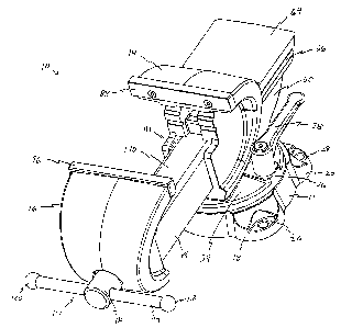
In FIGS. 1-14, the apparatus is identified generally by reference numeral 10
and
comprises a cast iron vise having a swivel base 12, back jaw member 14 and
front jaw
member 16. The base 12 has a generally elliptical shape and has four generally
arcuate
shaped feet 18, 20, 22 and 24 (hereinafter 18-24) extending therefrom. In the
embodiment shown, two feet 18 and 20 are located at least partially below the
front
-4-
CA 02420797 2003-02-27
section of the back jaw member 14, and two feet 22 and 24 are located at least
partially
below the rear section of the back jaw member 14. The shape of the base
enhances
stability of the apparatus 10 on the work surface. For example, feet 18 and 24
are larger
than feet 22 and 30 and/or set wider apart than feet 22 and 20, in order to
enhance the
stability of the apparatus for handling larger workpieces positioned between
the front and
back jaw members 16 and 14. More particularly, the enlarged shape and spacing
of the
feet 18 and 34, as illustrated in FIG. 7, allow the jaw members to be
separated by greater
distances and the apparatus to hold larger workpieces without allowing the
apparatus to
tip over due to the shift in weight away from the center of gravity of the
apparatus, (e.g.,
weight shift due to movement of the front jaw member 16 toward its furthest
most open
position).
Portions of the,upper surface of feet 18-24 are recessed for providing a level
surface via which the base may be fastened or secured to the work surface.
These
recessed level surfaces 26, 28, 30 and 32 (hereinafter 26-32) are ideal for
being engaged
by a bolt head, a nut, or a washer, to secure the base to the work surface.
The
countersunk nature of the surfaces 26-32 also allows at least a portion of the
fastener used
to lie below the curved upper surface of the feet 18-24, thereby reducing the
potential of
an article catching or snagging the fastener.
The back jaw member 14 is connected to the swivel base 12 and has a lower
pedestal portion 34 upon which the main body of the back jaw member rests. The
pedestal portion 34 has a generally circular shaped horizontal cross section
and is capable
of rotating about the base 12 so that the workpiece can be rotated with
respect thereto. A
raised portion 36 having a generally flat upper surface is provided on the
pedestal portion
34 for connecting locking handle 38 to the apparatus 10. The locking handle 38
secures
the back jaw member 14 at a desired position with respect to the base 12. More
particularly, the upper surface of the raised portion 36 defines an opening
through which a
gear lock bolt 40 passes. The locking handle 38 has a sleeve portion 42, and
an elongated
handle portion 44 extending therefrom. The elongate handle portion 44 tappets
away
from the sleeve 42 and has a rounded end portion 46 for providing an
ergonomically
desirable handle that is comfortable to grasp, rotate, and raise. The rounded
end also
allows the operator to "feel" the end of the handle without the need to
visually locate it,
-S-
CA 02420797 2003-02-27
and provides an additional amount of surface area with which the operator can
grasp the
handle 38 so that the operator can obtain a better grip and leverage to
operate the handle
38.
As seen in FIGS. 11 and 12, the sleeve 42 of the lock down handle 38 houses an
insert 48 which is internally threaded for receiving the threaded portion of
the gear lock
bolt 40. The insert 48 is generally cylindrical in shape with a polygonal
locking structure
48a located near the top thereof. The polygonal locking structure 48a defines
a threaded
bore to mate with the threaded portion of spring bolt S0. The preferred spring
bolt 50 is a
hex-head type bolt which serves to retain spring S2 in a cup-shaped recess S4,
which has
an aperture through which the threaded portion of the spring bolt SO passes or
is thread.
Located within the sleeve 42 is a mating recess similar in shape to the
polygonal locking
structure 48a. The polygonal locking structure 48a is held within the mating
recess via
the force exerted on the handle 38 from spring 52. Thus, allowing the handle
38 to
engage and rotate the insert 48 as desired.
The lock down handle 38 operates as a clutched actuator providing an increased
frictional relationship between the back jaw member 14 and the base 12 when
operated in
one direction, a decreased frictional relationship when operated in the
opposite direction,
and allowing the handle 38 to be raised and rotated to a plurality of
different positions
without affecting the relationship between the back jaw member 14 and the base
12. The
spring S2 normally biases the actuator handle 38 into engagement with the lock
created
by insert 48 and bolt 40 so that operation of the handle 38 will result in a
corresponding
operation of the lock, thereby tightening or loosening the lock. The actuator
handle 38
may be shifted against the spring to selectively disengage the mating surfaces
of the
sleeve 42 and the insert 48 in order for the actuator to be moved without
affecting the
2S position of the of the lock and released to re-engage the mating surfaces.
The lock bolt 40 is a shouldered bolt having a polygonal shaped shoulder
portion
countersunk into the base 12 to prevent the bolt 40 from moving when the
handle 38 and
insert 48 are in engagement and turned. For example, when the handle 38 is
rotated
clockwise, the gear lock bolt 40 is thread into the insert 48 and the insert
48 tightens the
pedestal 34 against the base 12 thereby increasing the frictional relationship
between the
back jaw member 14 and the base 12. After enough rotations, the back jaw is
effectively
-6-
CA 02420797 2003-02-27
secured in one position about the base 12.
When the handle 38 is rotated counterclockwise, the gear lock bolt 40 is
thread out
of (or removed from) the insert 48 and the insert 48 loosens the pedestal 34
of the back
jaw member 14 from the base 12 thereby reducing the frictional relationship
between the
back jaw member 14 and the base I2. After enough turns, the back jaw member
(and
front jaw member attached thereto) can be freely rotated about the base 12.
When the apparatus user desires to move the handle 38 without affecting the
relationship between the back jaw member 14 and the base IZ (e.g., without
rotating the
insert 48), he or she need only lift the handle 38 to compress the spring 50
and disengage
the sleeve 42 from the insert 48. This orientation allows the handle 38 to be
rotated
without affecting the relationship between the back jaw member 14 and the base
12.
Such handle movement may be desired for a number of reasons. For example, the
apparatus user may want to move the handle 38 in this fashion in order to
position it out
of his or her way or out of the way of the workpiece. Alternatively, the user
may want to
move the handle 38 in this fashion in order to position it in a location that
offers him or
her more desirable leverage with respect to the handle 38. Further, the user
may want to
move the handle 38 in this fashion due to space constraints of the environment
in which
the user is working or due to space constraints of the workpiece itself. In a
preferred
embodiment, the clutching action of the handle may be operated regardless of
the current
state of the relationship between the back jaw 14 and the base 12 (e.g.,
regardless of
whether the jaw members 14 and 16 are effectively secured to the base 12 in
one position
or are freely moveable about the base 12).
In alternate embodiments, the polygonal locking structure 48a may include a
mufti-toothed gear and the sleeve may include an annular ring having mating
teeth located
therein which engage one another when the actuator and lock are engaged and
clear one
another when the actuator and lock are disengaged. More particularly, when
engaged, the
teeth of the annular ring force the gear and insert to rotate alang with the
handle. When
disengaged, movement of the handle and annular ring do not result in a
corresponding
movement of the gear and insert.
Unlike ratcheting systems, such as those used in conventional socket wrenches,
the actuator and locking mechanism disclosed herein allow the clutched
actuator to be
_7_
CA 02420797 2003-02-27
engaged and disengaged by simply shifting the handle with respect to the lock,
and allow
the handle to be freely rotated in any direction (e.g., clockwise or
counterclockwise
rotation) so as to allow the user to selectively position the handle without
limitation or
restriction to account for any one of the various space constraints discussed
above.
Whereas, in a traditional ratchet systems having a socket and handle, the
ratchet must
either be removed from the driven member in order to reposition the handle in
either
direction or a switch must be actuated in order to convert the ratchet's
transmission from
one operating rotational direction to the other. Such restrictions and
limitations increase
the amount of time it takes to operate the handle and increase the likelihood
of the user
losing the handle and/or handle components.
In addition, traditional ratchet systems will not allow the user to position
the
handle in any desired position without taking further steps to ensure that the
handle will
not inadvertently rotate. For example, gravity will cause a traditional
ratchet system to
rotate to a vertical position with the handle extending down from the driven
member
unless the transmission of the ratchet system is adjusted to prevent the
rotation in that
direction. This restriction further increases the amount of time and effort it
takes to
operate a ratchet system.
Turning now to FIGS. 7 and 11, when the pedestal portion 34 is rotated about
the
base 12, the gear lock bolt 40 travels with, the pedestal portion 34 about an
arcuate path 56
(FIG. 7) defined by an inner portion 44 of the base 12. The path 56 allows for
the jaw
members 14 and 16 to rotate one hundred eighty degrees ( 180°) with
respect to the base
12. In alternate embodiments, the apparatus 20 may be configured such that the
jaw
members 14 and 16 can rotate three hundred and sixty degrees (360°)
with respect to the
base 12 (e.g., by making the path defined by inner portion 44 an annular ring
allowing for
360° rotation). In yet other embodiments, a variety of other degrees
and directions of
rotation may be achieved. The ability to rotate the jaw members 14 and I6
allows the
user to rotate the workpiece as desired and expedites the amount of time it
takes to work
on the workpiece.
The main body of the back jaw member 14 extends up from the pedestal portion
34 and into an anvil portion 60 and a jaw support portion 62. The anvil
portion 60 has a
generally flat surface 64 upon which an apparatus user may rest and/or strike
objects.
_g_
CA 02420797 2003-02-27
Located below this surface 64 are accessory slots 66 and 68 which, in the
preferred
embodiment, are used to anchor various accessories to the apparatus 10. Some
of these
accessories will be discussed further below with respect to FIGS. 17-22.
In the embodiment shown in FIGS. 1-14, the accessory slots 66 and 68 are in
the
S form of elongated horizontal recesses located within the sides of the anvil
portion 60 and
are generally parallel to the anvil surface 64. In their anchoring capacity,
the accessory
slots 66 and 68 are capable of retaining portions of accessories so that
additional uses of
the apparatus 10 may be had. For example, the ends of a pull-down clamp
bracket may
be inserted so that the workpiece may be worked on from above via the clamp.
An
example of this can be seen in FIG. 19.
In alternate embodiments, the accessory slots may be used to store various
types
of accessories to be used with the apparatus 10. For example, work supports,
such as
spacers or riser bars (as shown in FIG. 19), may be stored within the
accessory slots and
removed to adjust the height of the workpiece when desired. Alternatively,
tools such as
1 S a hex-key for tightening and/or loosening the spring bolt SO may be stored
in accessory
slots located in the anvil portion of the apparatus or in an alternate
accessory slot located
about the apparatus.
As can be seen best in FIGS. 1, 3, 9, 11 and 14, the back jaw member 14 also
contains an inner region 70 having a channel or passageway 72 through which a
beam
108 from the front jaw member 16 and a screw thread or spindle 76 may pass.
Within the
inner region 70 of the apparatus 10 is a back jaw keyway (or nut) 78. The
keyway 78
contains a generally vertical bore or channel 80 and a generally horizontal
bore or channel
82 which are internally threaded. The vertical bore 80 is used as a nut for
attaching the
keyway 78, back jaw member 14, and base 12 together. More particularly,
shoulder bolt
84 is fed through openings in the base 12 and back jaw member 14 and threaded
into the
bore 80. The shoulder bolt 84 has a shoulder or collar portion 86 which allows
the jaw
member 14 to swivel with respect to the base. Thus, the keyway 78 actually
serves as a
nut to the bolt connecting the back jaw member 14 to the base 12. The
horizontal bore 82
is also used as a nut for receiving the threaded screw or spindle 76 of the
apparatus. This
configuration will be explained in further detail below with respect to the
operation of the
apparatus 10.
-9-
CA 02420797 2003-02-27
The jaw support portion 62 of the back jaw member 14 includes an upper or top
jaw 88 for holding various types of workpieces and lower jaws, such as pipe
jaws 90 and
92, for holding various sizes of rounded objects such as pipes or other
objects having non-
uniform surfaces. In the embodiment shown, the top jaw 88 is made from
hardened steel
and the pipe jaws are cast into the apparatus 10 as a permanent fixture. In
alternate
embodiments, however, a number of different jaws may be used. For example, the
top
jaw 88 may be replaced with aluminum jaws, fiber jaws, rubber jaws, prism
jaws, copper
jaws, polyurethane jaws, or the like, depending on the type of workpiece to be
secured via
the jaw. As an example, if a softer metal is to be secured by the jaw, copper
or
polyurethane jaws may be used in order to prevent the apparatus from damaging
the
workpiece.
Furthermore, the face of the jaws may be serrated, smooth, or configured to
hold
particular types of workpieces. For example, if the apparatus 10 is often used
to secure
particular types of workpieces, the jaws may be configured specifically for
holding that
particular material. As an example, if the apparatus 10 is often used to hold
piping
smaller than that capable of being held in the pipe jaws, the top jaws may
contain
horizontal or vertical grooves in their face to better secure the workpiece.
In some
instances, the jaws may be reversible, having a serrated face on one side and
a smooth
face on the other. In yet other instances, magnetic jaws may be attached to
the top jaws
for temporary workpiece holding. Such jaws allow the apparatus user to protect
both the
jaws of the apparatus 10 and the workpiece from marring and distortion during
clamping
action. Typically these magnetic jaws or caps are constructed with two built-
in circular
magnets located on the backside of the magnetic jaw attachment to connect the
caps to the
top jaws of the apparatus 10 and to keep from magnetizing the clamped
workpiece and/or
collecting metal filings on the face of the caps.
In addition to the versatility of the top jaw, the apparatus 10 may be
configured
with replaceable pipe jaws 90 and 92 instead of permanent pipe jaws. Such a
configuration allows different types of pipe jaws to be used (e.g., aluminum,
fiber, rubber,
etc.), and can allow for self centering pipe jaws to be used so that the
workpiece is
properly secured.
-10-
CA 02420797 2003-02-27
The front jaw member 16 has a jaw support portion 94 containing top and pipe
jaws 96, 98 and 100 similar to those on the back jaw member 14. In the
embodiment
shown, the top jaw 96 is replaceable and the pipe jaws 98 and 100 are cast
into the front
jaw member 16. As shown in FIG. 14, the top jaws 88 and 96 are attached to the
jaw
S support portions 62 and 94 via fasteners 102. In the embodiment shown, the
fasteners
102 consist of screws which are partially fed through openings in the jaws 88
and 96 and
thread into bores located on the jaw support portions 88 and 96. Preferably,
at least one
of the jaws 88 and 96 have graduated ruler markings on their upper surface so
that an
apparatus user can make measurements with ease and/or move a workpiece by
measured
amounts while it is loosely clamped by the apparatus 10. An example of this
can be seen
in FIG. 18, by looking at the image of the jaws shown through the magnifying
lens.
Extending from the lower portion of the front jaw member 16 is the front jaw
beam 108 (slide bar or channel beam) which covers and protects the elongated
threaded
member or screw 76. In the embodiment shown, the jaw beam 108 consists of an
elongate horizontal sleeve formed from steel, which is generally U-shaped and
covers the
top and sides of the screw 76. The upper surface 110 of the beam 108 is
generally flat for
providing a surface upon which a workpiece can be rested andlor balanced.
Furthermore,
the edges of the beam 108 are rounded to reduce the risk of scratching or
marking a
surface of the workpiece. The back jaw has a lip portion 111 which is
generally U-shaped
and extends out from the main body of the back jaw 14. The lip portion 111
provides
support for the beam 108 and provides upper surfaces which are level with the
upper
surface of the beam 108. This configuration helps strengthen the apparatus 10
and
support workpieces resting between the jaw members 14 and 16.
When the jaws 88 and 96 are in the closed position, a portion of the beam 108
extends out beyond the back jaw member 14, as can be seen in FIGS. 2 and 4.
This is not
so when the jaws 88 and 96 are fully opened, as can be seen in FIG. 10.
Further, in the
embodiment shown, the end of the beam that extends out from the back jaw
member 14
when the jaws 88 and 96 are fully closed is curved to match that of the outer
surface of
the back jaw member for esthetic purposes. In the preferred embodiment, a
portion of the
beam 108 will always be present above the screw 76, in order to prevent
anything from
being rested on the screw 76 and/or damaging the screw, (e.g., bending the
screw, denting
-11-
CA 02420797 2003-02-27
the screw threads, etc.).
The lower portion of the front jaw 16 also includes a passageway through which
the screw 76 is passed for connection to the main apparatus handle 112. As can
be seen
in FIG. 13, the passageway is defined by openings in the outer and inner walls
113 and
115 of the front jaw member 16, and positions the screw 76 in line with the
keyway 78 so
that the screw 76, when turned, travels in a straight line. This straight line
configuration
reduces thread wear in the bore 82 of keyway 78 and increases the overall
clamping
power of the apparatus 10 due to the cooperating engagement between the screw
threads
and the internal bore threads of the keyway 78.
The main apparatus handle (spindle handle or slotted T-handle) 112 has an
elongated lever portion 114 extending through a collar portion 116 of the
screw 76. The
lever portion 114 contains ball-shaped ends I 18 and 120 and can slide through
the collar
116 in either direction until one of the ends 118 and 120 abuts the collar
116. This allows
the user to increase the length of the lever portion 114 thereby increasing
the amount of
leverage the user has to rotate the handle 112. This feature also allows the
lever portion
114 to be adjusted to account for environmental andlor workpiece space
constraints. In
the embodiment shown, the screw 76 is made from cold rolled steel and the ball
ends 118
and 120 are forged from the handle stock so that they will not come loose.
Rubber collars
may be positioned about the Iever portion 114 near the ball-shaped ends 118
and 120 in
order to prevent metal-to-metal contact between the ends 118 and 120 and the
collar
portion 116.
As shown in FIG. 14, portion 122, which is located adjacent to the collar 116,
is
non-threaded and rests within the passageways defined by inner and outer walls
115 and
113 of the front jaw member 16. Next to this portion of the screw 76 is a
recessed
channel 124 within which washer 126 rests. When the screw is inserted in the
passageway of the front jaw member 16 and during use of the apparatus, the
washer 126
abuts the inner wall 115 of jaw member 16. Adjacent this portion of the screw
76 is
another non-threaded portion 128 around which spring I30 is placed. Adjacent
portion
128 is another recessed channel 132 within which a locking washer, such as E-
ring 134,
rests. This Locking washer 134 compresses the spring 130 against washer 126,
which in
turn presses against the inner wall 115 of front jaw member 16. Such a
configuration
-12-
CA 02420797 2003-02-27
holds the screw 76 into the front jaw member 16 and effectively gives the
apparatus 10 a
spring loaded handle and screw assembly. Such a configuration helps ensure
that there
will be immediate engagement between the threaded portion of the screw 76 and
the nut
78, and ensures the screw 76 is in proper alignment with the nut 78. These
features assist
in reducing, if not eliminating, play in the handle 112.
During operation of the apparatus 10, the handle 112 is rotated in the fashion
discussed above in order to open and close the jaws 88, 90, 92, 96, 98 and
100. More
particularly, when the handle 1 I2 is rotated clockwise, the screw 76 is
thread into the
keyway or nut 78 bringing the front jaw support portion 94 closer to the back
jaw support
portion 62. After enough turns, the jaws 88 and 96 are completely closed
preventing
additional rotation of the handle. When the handle 112 is rotated
counterclockwise, the
screw 76 is threaded out of (or backed out ofj the nut 78 causing the front
jaw support
portion 94 to move farther away from back jaw support 62. Such rotation
spreads the
jaws apart allowing the apparatus 10 to work with larger workpieces. In most
applications, the apparatus 10 will be mounted to a work surface such as a
bench or table
and will be used to clamp a desired workpiece. During other applications,
however, the
apparatus may be used to spread items apart, (e.g., used as a spreader). For
example,
vertical bars may be inserted into the holes in the top jaws 88 and 96, (as
shown in FIGS.
17 and 18), and the handle 1 I2 may be turned to crank the front jaw member 16
away
from the back jaw member 14. With such a configuration, a workpiece separated
by the
vertical bars would be spread apart as jaw 96 separates or opens from jaw 88.
In alternate embodiments of the invention, the clutched handle described above
may be used as the main apparatus handle or spindle handle in order to provide
more
control over the handles operation. For example, in embodiments having
stationary
bases, (which means there is no lock down handle), a clutched handle may be
provided as
the main apparatus handle so that the apparatus user can reposition the handle
out of his
or her way, or so the user can position the handle in a location where he or
she can get
more leverage to operate the handle, or so the user can position the handle as
required by
various environmental space constraints (?.g., space constraints with the work
area, space
constraints with the workpiece, etc.).
..13_
CA 02420797 2003-02-27
As another example, such a clutched spindle handle may be ideal for vises
mounted on a drill press in which the user cannot complete a full rotation of
the handle.
In such instances, the user can simply rotate the handle as far as he or she
can, disengage
the handle from the rotating screw or spindle, position the handle back to the
desired
S starting location, and re-engage the handle for further rotation of the
screw or spindle.
Such a clutched spindle handle also allows the apparatus user to tighten the
jaws
of the apparatus to the desired amount and then position the handle so that
the lever arm
or handle is pointing straight downward. This minimizes the effect gravity can
have on
the handle and the desired jaw setting. For example, with a traditional
spindle handle, the
lever of the handle may be left at a position other than pointing straight
down when the
desired jaw setting has been reached. As such, the weight of the handle in
combination
with gravity (which is continually trying to return the handle to the position
where it
points straight downward) may be sufficient to change or affect the desired
jaw setting.
Use of a clutched spindle handle can avoid such a problem.
1 S In FIGS. 1 S and 16, an alternate apparatus for securing a workpiece in
accordance
with the invention is shown with the first and second jaw members aligned so
that their
opening is positioned off to the side of the apparatus base so that workpieces
may be
suspended off of the end of the worksurface to which the apparatus is mounted
or resting
on. For convenience, features of the alternate embodiment illustrated in FIGS.
1 S and 16
that correspond to features already discussed with respect to the embodiments
of FIGS. 1-
14 are identified using the same reference numeral in combination with an
apostrophe (')
merely to distinguish one embodiment from the other, but otherwise such
features are
similar. The advantage to having the jaw members 14' and 16' aligned with
their opening
(identified by arrows 121 ) off to the side of the base 12' is that the
apparatus can be used
2S with a workpiece extending off to the side of the worksurface upon which
the apparatus is
mounted or resting. For example, in one application the apparatus 10' may be
used to
' secure a workpiece extending up from the floor of a workshop and off to the
side of a
workbench upon which the apparatus 10' is mounted. Thus, the alignment of the
jaw
members 14' and 16' may be adjusted to provide such capabilities.
Various accessories may be used in conjunction with the apparatus described
herein. For example, in FIGS. 17 and 18, an alternate apparatus for securing a
workpiece
- 14-
CA 02420797 2003-02-27
in accordance with the invention is shown generally at reference numeral 200
and is being
used in conjunction with a magnifying lens, such as magnifying glass 202. The
magnifying glass 202 is connected to an adjustable arm 204 so that it can be
positioned
over various portions of the apparatus 200, workpiece, and work surface. The
arm 204 is
connected to a power supply 206 so that the magnifying glass 202 can be
illuminated
and/or illuminate the region being observed through the magnifying glass 202.
The
power supply 206 has a power switch 208 and a illumination adjustment knob 210
for
adjusting the amount of light given off by the magnifying glass 202. In the
embodiment
shown, the power supply 206 is battery operated and supplies power from the
battery to
the illumination device of the magnifying glass 202. In alternate embodiments,
the power
supply may have a power cord capable of supplying power from an outlet to the
illumination device.
The power supply 206 is anchored to the apparatus 200 via braces such as legs
212 which extend down from the bottom or side surface of the power supply 206
and into
1 S accessory slots 214 and 216 of the apparatus 200. More particularly, the
power supply
206 is slid onto the apparatus 200 so that the ends of the braces Z 12 slide
into the
accessory slots 214 and 216. In another embodiment, the power supply 206 may
be
clamped or fastened to the anvil portion of the apparatus, and/or may contain
magnets for
attaching the power supply to the apparatus. For example, at least a portion
of the bottom
of the power supply 206 may be magnetic and capable of connecting the power
supply
206 to the apparatus 200. The magnets may be used in conjunction with the
clamps or
braces mentioned above, or in place of these items.
Another accessory being used with the apparatus 200 is workpiece stop 220,
which has an elongated shaft 222 extending into a receiving slot (or accessory
slot)
located in the main body of the back jaw member, preferably below that
member's jaw
and near the face of the jaw support portion. In the embodiment shown, the
receiving slot
extends all the Way through the back jaw member. The work stop 220 is adjusted
to bring
the stop lever 224 and end stop 226 closer to the jaws or farther therefrom.
Once the
desired position is reached, the workpiece is positioned between the jaws of
the apparatus
200 and butted up against the end stop 226. This accessory 220 ensures that a
workpiece
or multiple workpieces can be returned to the exact position within the vise
each and
-15-
CA 02420797 2003-02-27
every time the user desires to do so. The receiving slot used for this
accessory may be
found in either the back jaw member or the front jaw member, as can be seen
more clearly
in FIGS. 20 and 22, and preferably passes all the way through the entire jaw
member so
that the workpiece stop 220 can be inserted however far is desired and/or used
on either
side of the apparatus 200.
In FIG. 19, the apparatus 200 is used in conjunction with a hold down clamp
228,
which is anchored to the apparatus 200 via brackets (or legs) 230 and 232,
which have
ends resting within the accessory slots 214 and 216. With this configuration,
a workpiece
can be positioned and clamped down onto the anvil portion of the apparatus
200. In some
instances, it may be desirable to place work supports, such as spacers or
riser bars 234
and 236, underneath the workpiece to raise it a desired amount. For example,
if the user
intends to drill the workpiece, the user will want to raise the workpiece off
of the anvil
surface at least a minimal amount so as not to damage the apparatus 200 and/or
drill bit
once the bit passes through the workpiece. In operation, the user turns the
spindle handle
1S 237 thereby moving the clamp 239 closer to or farther from the workpiece.
In FIG. 20, the apparatus 200 is used in conjunction with a hold down clamp
228
and a v-block (or 90° workpiece support) 238. Such an accessory 238 is
frequently used
when the workpiece is round or cylindrical in shape or when the workpiece has
corners.
With such a conf guration, the apparatus can be used to perform one task with
the hold
down clamps, while allowing the jaw members to be used for another task.
In FIG. 21, the apparatus 200 is used in conjunction with two hold down clamps
228 and 240. Again, each clamp 228 and 240 is anchored to the apparatus 200
via
brackets (or legs) 230, 232, 242 and 244. In this way, the clamps of the hold
downs 228
and 240 can be tightened down towards the anvil portion surface area of the
vise and can
apply pressure to the workpiece located thereon.
In FIG. 22, the apparatus 200 is used in conjunction with an arbor press 246,
which is secured to the apparatus 200 via brackets 248 and 250 and accessory
slots 214
and 216. Such an accessory 246 may be used to exert a strong force in a
concentrated
area of a workpiece. When the user turns the press handle 252 clockwise, the
press 254 is
lowered down against the workpiece.
-16-
CA 02420797 2003-02-27
The engagement between the accessory and the accessory slots 214 and 216 is
essentially wobble free, but allows the ends of the legs or brackets of the
accessory to ride
freely in and out of the slots 214 and 216. In the case of clamp or arbor
press accessories,
once the accessory has been positioned within the slots 214 and 216 and the
clamp has
S been lowered into engagement with the workpiece, the ends of the legs or
brackets are
pulled against the top surface of the slots effectively locking the accessory
into its current
position within the slot. With respect to the power supply and similar type
accessories,
the accessory may contain additional clamping members for tightening the
accessory
against the apparatus 200, or may contain magnets for achieving a similar
function.
In the embodiments illustrated in FIGS. 1-22, the lip portions of the
accessories
that extend into the slots of the apparatus are complimentary in shape to the
slots. In a
preferred form, the accessories are removed from the apparatus by sliding the
accessories
off the end of the anvil portion of the apparatus. However, in alternate
embodiments, the
lip portions may be made of a resilient material which allows the lip portions
to be
temporarily deformed so that the accessories can be lifted up off the anvil
portion rather
than slid off its side. For example the accessory could be lifted directly up
from the
apparatus causing both lip portions to deform simultaneously, or the accessory
could be
removed from the slots by removing the lip portions one side at a time.
In alternate embodiments, other mortise and tenon, or tongue and groove,
configurations may be used to connect the accessories to the apparatus. For
example, the
apparatus and accessories may be connected to one another via a dovetail joint
configuration, (e.g., a flaring tenon and mortise configuration). In yet other
embodiments, the mortises may be located in the accessory and the tenons
located on the
apparatus, or the accessories may have both tenon and one mortise portions and
the
apparatus may have complimentary mortise and tenon portions. Thus, it should
be
understood that a variety of joints or connections may be used to connect the
accessories
to the apparatus, (e.g., such as magnetic bases as discussed above with
respect to FIGS.
17 and 18).
Furthermore, although some of the more useful accessories for use with an
apparatus for securing a workpiece have been discussed and/or illustrated, one
of ordinary
skill in the art should know that a plurality of other accessories may be used
in
-17-
CA 02420797 2003-02-27
conjunction with the apparatus given its novel accessory connection apparatus
and
methods. Thus it is apparent that there has been provided, in accordance with
the
invention, an apparatus for securing a workpiece that fully satisfies the
objects, aims, and
advantages set forth above. While the invention has been described in
conjunction with
S specific embodiments thereof, it is evident that many alternatives,
modifications, and
variations will be apparent to those skilled in the art in light of the
foregoing description.
Accordingly, it is intended to embrace all such alternatives, modifications,
and variations
as fall within the spirit and broad scope of the appended claims.
-18-