Language selection

Search

Patent 2420825 Summary

Third-party information liability

Some of the information on this Web page has been provided by external sources. The Government of Canada is not responsible for the accuracy, reliability or currency of the information supplied by external sources. Users wishing to rely upon this information should consult directly with the source of the information. Content provided by external sources is not subject to official languages, privacy and accessibility requirements.

Claims and Abstract availability

Any discrepancies in the text and image of the Claims and Abstract are due to differing posting times. Text of the Claims and Abstract are posted:

  • At the time the application is open to public inspection;
  • At the time of issue of the patent (grant).
(12) Patent Application: (11) CA 2420825
(54) English Title: DIFFUSER FOR DEODORIZING PRODUCTS TO BE APPLIED TO VEHICLE VENT-HOLES
(54) French Title: DIFFUSEUR DE PRODUITS DEODORANTS POUR ORIFICES D'AERATION D'UN VEHICULE
Status: Deemed Abandoned and Beyond the Period of Reinstatement - Pending Response to Notice of Disregarded Communication
Bibliographic Data
(51) International Patent Classification (IPC):
  • B60H 1/24 (2006.01)
  • A61L 9/12 (2006.01)
  • B60H 3/00 (2006.01)
(72) Inventors :
  • VAN DER LINDEN-DOUW, JOLANDE EMILIE
(73) Owners :
  • DE LEURIKS B.V.
(71) Applicants :
  • DE LEURIKS B.V.
(74) Agent: ROBIC AGENCE PI S.E.C./ROBIC IP AGENCY LP
(74) Associate agent:
(45) Issued:
(22) Filed Date: 2003-03-04
(41) Open to Public Inspection: 2004-09-04
Availability of licence: N/A
Dedicated to the Public: N/A
(25) Language of filing: English

Patent Cooperation Treaty (PCT): No

(30) Application Priority Data: None

Abstracts

English Abstract


It is herein described a diffuser for deodorizing products of the type
consisting of an element provided with means apt to allow its application in
correspondence with a vehicle vent-hole, the said diffuser showing
openings for the inlet and outlet of an air flow apt to reach a deodorizing
product introduced inside an envelope consisting of a semipermeable
membrane apt to allow the passage of the perfumed oil molecules when it
is reached by an air flow.
Means are provided apt to control the said air flow which reaches the said
deodorizing product, consisting of a bored disk placed in contact with a
wall wherein there are openings for the air flow inlet, the said disk can be
rotated between a first position wherein it closes the said air inlet openings
to a second position wherein it opens the said openings, between the said
base and the said disk for the closure of the air inlet openings, a plurality
of ports being provided drawn in a diffuser wall and apt to allow the outlet,
throughout the environment, of the air flow corning from the vent-holes.


Claims

Note: Claims are shown in the official language in which they were submitted.

6
CLAIMS
1. A diffuser for deodorizing products of the type consisting of a body
element apt to contain a certain quantity of deodorizing product and
provided with means apt to allow its application in correspondence with a
vehicle vent-hole, the said diffuser showing openings for the inlet and
outlet of an air flow apt to reach this deodorizing product, characterized in
that the said deodorizing product is introduced inside an envelope
consisting of a semipermeable membrane apt to allow the passage of the
perfumed oil molecules when it is reached by an air flow.
2. A diffuser for deodorizing products according to claim 1, characterized
in that the air flow inlet openings are provided for in correspondence with
the diffuser bottom wall and the perfumed air outlet openings in
correspondence with the lateral wall, near the upper edge thereof.
3. A diffuser for deodorizing products according to claim 2, characterized
in that means are provided apt to control the said air flow which touches
the said deodorizing product.
4. A diffuser for deodorizing products according to claim 3, characterized
in that the said means consist of a bored disk placed in contact with a wall
wherein there are openings for the air flow inlet, the said disk can be
rotated from a first position wherein it closes the said air inlet openings to
a second position wherein it opens the said openings.
5. A diffuser for deodorizing products according to claim 3 or 4,
charaterized in that between the said base and the said disk which closes
the air inlet openings, there is a plurality of ports drawn in a diffuser
wall,
apt to allow the outlet, throughout the environment, of the air flow coming

7
from the vent-holes.
6. A diffuser for deodorizing products according anyone of the previous
claims, charaterized in that luminous means are provided to be activated
when the diffuser is in operation.
7. A diffuser for deodorizing products according to claim 6, wherein the
said luminous means consist of a LED visible through the diffuser cover
and fed by a battery contained into the said diffuser, the feeding circuit of
the said LED being closed when the said disk for the opening and closing
of the air flow inlets is put in an opening position thereof.
8. A diffuser for deodorizing products according to anyone of the previous
claims, characterized in that a cover is provided which can be opened to
allow the replacement of the envelope of the deodorizing product.

Description

Note: Descriptions are shown in the official language in which they were submitted.


CA 02420825 2003-03-04
1
"DIFFUSER FOR DEODORIZING PRODUCTS TO BE APPLfED TO
VEHICLE VENT-HOLES "
This invention proposes a diffuser for deodorizing products to be applied
s to vent-holes, in particular of vehicles and the Pike.
The diffuser is planned to be used with deodorants contained into a sachet
made of a membrane which is waterproof but permeable to perfumed oil
and when is reached by a blast of air, looses the perfume molecules.
The diffuser shows a plurality of adjustable openings for the air access,
1o which air is directed to lick the membrane containing the deodorant to
diffuse all over the environment.
The diffuser is preferably provided with a LED fed by a tab battery
contained into the diffuser and can be activated by the lever which controls
the opening of the air inlet vent-holes.
1s Different systems to perfume the interior of vehicles or the like are well
known.
For example deodorizing products are known consisting of a support in a
porous material impregnated with perfumed oil which, once exposed to the
air, releases the perfume in the environment.
zo Containers are furthermore known which are filled with deodorizing
. granules or paste and are closed by a cover which is partially opened to
allow the perfume to spread in the environment.
These containers of different types are generally fixed to vehicle parts
such as the dashboard, through a bi-adhesive ribbon, Velcro~ or another
25 similar system.

CA 02420825 2003-03-04
2
Containers are also known which arE~ addressed to be fixed in
correspondence with the vent-holes of a car and which consist of a box
provided with a grille or a series of inlet ports and a series of outlet ports
on the opposite wall.
s These containers are generally filled with granule deodorant so that the
ventilation air provides to collect the perfume and fo spread the same
inside the vehicle.
Into this sector can be inserted the present invention which proposes a
diffuser for deodorizing products to be applied to the vehicle vent-holes,
io the diffuser being provided to be used together with a deodorant
packaging contained into an envelope made of a semipermeable
membrane, which allows the passage of the perfumed oil molecules
which, when the membrane is reached by a blast of air, get out by
spreading in the environment.
is The diffuser according to the invention shows on its bottom wall a
plurality
of adjustable air inlet vent-holes and is provided with a LED powered by a
battery placed into the diffuser, which LED lights up when the air inlet
vent-holes are open.
A device results therefrom which is particularly practical and efficient,
2o simple to be assembled and which allows an easy replacement or' the
. deodorant.
This invention will be now described in detail, by way of a non-restrictive
example, with reference to the enclosed figures wherein;
~ Figures 1, 2 and 3 are respectively a top view, a side view and a
2s bottom view of the diffuser according to the invention with the cover

CA 02420825 2003-03-04
J
CIOSed;
~ Figure 4 is a side view of the diffuser with the cover while it is going to
open;
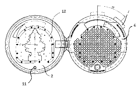
. Figure 5 is the top view of the diffuser with the cover opened and the
s envelope with the deodorant fit in;
~ Figure 6 is the sectional view of the diffuser according to the invention
with the air flow paths highlighted.
With reference to the figures, with reference 1 is indicated the diffuser,
according to the invention, in its whole, which comprises a body 2, in this
io specific case having a round base, provided with coupling arms 15 of
known type, for the fixing of the same on the vehicle vent-hole.
Upwardly the diffuser is closed by a cover 3 connected to the body 2
through a flexible plastic tab 4.
The body 2 shows at its base a series of openings 5 through which the air
Is coming from the vehicle ventilation system can enter the diffuser.
A disk 6 or the like (figure 6) provided with openings similar to the
openings 5 of the diffuser, rests on the bottom of the latter and shows a
tooth or a projecting lever 7, through which it is possible to rotate the disk
6 inside the diffuser to carry the same from a position wherein the
ao openings present in the disk match with the openings 5, allowing the free
passage of the air, to a position wherein the disk closes the openings 5,
In the middle of the body 2 there is a cylindrical support 8 wherein a tab
battery 9 is housed which feeds a LED diode 10 housed in the body 2 and
visible through a port 11 present in the cover 3.
2s The feeding circuit of the diode 10 is preferably closed to feed the LED,

CA 02420825 2003-03-04
when the disk 6 is rotated by acting on the lever 7 to carry the said disk in
the opening position of the air inlet ports 5.
Figure 5 shows the diffuser with the deodorant sachet, set out with
reference 12, fitted inside.
s On the lateral wail of the diffuser 2 (see figure 2) there are a series of
air
outlet openings, indicated with reference 13, placed in the upper part and
an additional series of openings 14 placed near the base of the body 2,
below the disk 6.
The operation takes place as follows:
io The diffuser is put into a vent-hole with its base laid on the edge of the
said vent-hole where it is held by the arms 15, which engage a support
usually present inside the vent-holes.
The cover 3 is opened and the semipermeable envelope containing the
deodorant is put in.
is Once the cover is closed, the device is ready to be used.
With the disk 6 in a closing position of the openings 5, the air flow coming
from the vent-hole slowly gets out laterally through the openings 14, at the
base of the diffuser, without the perfume is spread in the environment.
By rotating the disk 6 through the lever 7, the openings 5 open and the air
2o coming from the vehicle ventilation system licks the deodorant envelope,
from which, through the semipermeable membrane, the perfume
molecules get out and are spread in the environment always through the
openings 13.
The activation of the perfume diffusion is also announced by the lighting of
2s the LED 10, further to the closure of the feeding circuit consequent to the

CA 02420825 2003-03-04
J
rotation of the disk 6.
Different forms of execution can be pro~,rided for with reference to the
same idea of solution, but they have anyway to be considered a!I
comprised within this invention.

Representative Drawing
A single figure which represents the drawing illustrating the invention.
Administrative Status

2024-08-01:As part of the Next Generation Patents (NGP) transition, the Canadian Patents Database (CPD) now contains a more detailed Event History, which replicates the Event Log of our new back-office solution.

Please note that "Inactive:" events refers to events no longer in use in our new back-office solution.

For a clearer understanding of the status of the application/patent presented on this page, the site Disclaimer , as well as the definitions for Patent , Event History , Maintenance Fee  and Payment History  should be consulted.

Event History

Description Date
Application Not Reinstated by Deadline 2009-03-04
Time Limit for Reversal Expired 2009-03-04
Deemed Abandoned - Failure to Respond to Maintenance Fee Notice 2008-03-04
Inactive: Abandon-RFE+Late fee unpaid-Correspondence sent 2008-03-04
Application Published (Open to Public Inspection) 2004-09-04
Inactive: Cover page published 2004-09-03
Inactive: IPC assigned 2003-04-22
Inactive: First IPC assigned 2003-04-22
Application Received - Regular National 2003-03-28
Filing Requirements Determined Compliant 2003-03-28
Letter Sent 2003-03-28
Inactive: Filing certificate - No RFE (English) 2003-03-28

Abandonment History

Abandonment Date Reason Reinstatement Date
2008-03-04

Maintenance Fee

The last payment was received on 2007-02-14

Note : If the full payment has not been received on or before the date indicated, a further fee may be required which may be one of the following

  • the reinstatement fee;
  • the late payment fee; or
  • additional fee to reverse deemed expiry.

Please refer to the CIPO Patent Fees web page to see all current fee amounts.

Fee History

Fee Type Anniversary Year Due Date Paid Date
Application fee - standard 2003-03-04
Registration of a document 2003-03-04
MF (application, 2nd anniv.) - standard 02 2005-03-04 2005-02-28
MF (application, 3rd anniv.) - standard 03 2006-03-06 2006-02-17
MF (application, 4th anniv.) - standard 04 2007-03-05 2007-02-14
Owners on Record

Note: Records showing the ownership history in alphabetical order.

Current Owners on Record
DE LEURIKS B.V.
Past Owners on Record
JOLANDE EMILIE VAN DER LINDEN-DOUW
Past Owners that do not appear in the "Owners on Record" listing will appear in other documentation within the application.
Documents

To view selected files, please enter reCAPTCHA code :


To view images, click a link in the Document Description column. To download the documents, select one or more checkboxes in the first column and then click the "Download Selected in PDF format (Zip Archive)" or the "Download Selected as Single PDF" button.

List of published and non-published patent-specific documents on the CPD .

If you have any difficulty accessing content, you can call the Client Service Centre at 1-866-997-1936 or send them an e-mail at CIPO Client Service Centre.


Document
Description 
Date
(yyyy-mm-dd) 
Number of pages   Size of Image (KB) 
Abstract 2003-03-04 1 27
Description 2003-03-04 5 147
Drawings 2003-03-04 3 52
Claims 2003-03-04 2 60
Representative drawing 2003-05-21 1 24
Cover Page 2004-08-16 1 57
Courtesy - Certificate of registration (related document(s)) 2003-03-28 1 130
Filing Certificate (English) 2003-03-28 1 169
Reminder of maintenance fee due 2004-11-08 1 110
Reminder - Request for Examination 2007-11-06 1 119
Courtesy - Abandonment Letter (Maintenance Fee) 2008-04-29 1 178
Courtesy - Abandonment Letter (Request for Examination) 2008-05-27 1 165
Fees 2005-02-28 1 30
Fees 2006-02-17 1 34
Fees 2007-02-14 1 42