Note: Descriptions are shown in the official language in which they were submitted.
CA 02421136 2003-03-05
BICYCLE CRANK ASSEMBLY AND ASSEMBLY TOOLS
BACKGROUND OF THE INVENTION
The present invention is directed to bicycles and, more particularly, to a
bicycle crank
assembly and to the components and tools used to assemble the bicycle crank
assembly.
A bicycle bottom bracket is a cylindrical tube portion of the bicycle frame
used to
rotatably mount the pedal assembly to the bicycle. The pedal assembly usually
comprises right and left crank arms, each of which has a pedal attached to one
end. The
other end of each crank arm is attached to an axle that extends through the
bottom
bracket. A bearing assembly is disposed between the axle and the bottom
bracket at
each side of the bottom bracket for rotatably supporting the axle, and one or
more front
sprockets usually are attached to the right side crank arm for driving the
bicycle chain.
The front sprockets) must be properly aligned with the rear sprockets)
attached to the
rear wheel so that the bicycle operates properly. Thus, the axle must be
properly
positioned laterally within the bottom bracket. In one known teclnique fox
adjusting the
lateral position of the axle, the axle is rotatably centered and laterally
fixed within a
tubular member by bearing assemblies installed at opposite ends of the tubular
member.
The axle and tubular member then are placed inside the bottom bracket. Adapter
members having threaded outer peripheral surfaces are screwed into the
threaded inner
peripheral surface of the bottom bracket on opposite sides of the tubular
member so that
the lateral position of the axle is determined by how much of each adapter
member is
screwed into the bottom bracket. Unfortunately, since the adapter members must
be
long enough to accommodate many different lateral positions of the axle,
usually a
portion of the threaded outer peripheral surface of each adapter member is
exposed, and
this often results in rusting and dirt contamination of the threads.. Also,
since the axle is
fixed to the tubular member through the bearing assemblies, the axle, tubular
member
and bearing assemblies ordinarily must be replaced as a unit.
CA 02421136 2003-03-05
SUMMARY OF TFIE INVENTION
The present invention is directed to a bicycle crank assembly wherein the
lateral
position of the axle may be adjusted without one or more of the disadvantages
of prior
art axle assemblies. In one embodiment of the present invention, a bicycle
crank arm
apparatus includes an axle having a first end portion and a second end
portion, wherein
the first end portion has an outer peripheral surface and a threaded inner
peripheral
surface; an axle bolt having a threaded outer peripheral surface screwed into
the
threaded inner peripheral surface of the first end portion of the axle; a
crank arm having
an axle mounting boss defining an opening for receiving the first end portion
of the axle
therein, wherein the axle mounting boss includes a first fastener for
tightening the crank
arm mounting boss around the first end portion of the axle; and wherein the
crank arm
boss is positioned axially inwardly of the axle bolt. At least one advantage
of this
structure is that the axle bolt may be used to laterally position the axle and
the crank
arms relative to each other, and the crank arm may be used to cover any
threaded
portion of the axle bolt that is not screwed into the axle.
In one embodiment of an axle bolt used to assembly the crank arm to the axle,
an axle
bolt includes a bolt body having a threaded outer peripheral surface and an
inner
peripheral surface defining an opening. A plurality of splines are
circumferentially
disposed on the inner peripheral surface of the bolt body, and a flange
extends radially
outwardly from the bolt body.
In one embodiment of a tool for screwing the axle bolt into the axle, the tool
comprises
a tool body, a plurality of splines circumferentially disposed on an outer
peripheral
surface of the tool body, and a tool operating member extending radially
outwardly
from the tool body.
In one embodiment, there is provided a crank arm comprising a crank arm body
having
an axle mounting boss on a first end and a pedal mounting boss on a second
end;
2
CA 02421136 2003-03-05
wherein the axle mounting boss defines an opening for receiving an axle
therein;
wherein the axle mounting boss includes a first mounting ear in close
proximity to a
second mounting ear; wherein the first mounting ear includes a first fastener
opening;
wherein the second mounting ear includes a second fastener opening; wherein
the first
mounting ear includes a third fastener opening in close proximity to the first
fastener
opening; and wherein the second mounting ear includes a fourth fastener
opening
disposed in close proximity to the second fastener opening.
In one embodiment of the invention, there is provided a bicycle crank arm
apparatus
comprising: an axle having a first end portion and a second end portion,
wherein the
first end portion has an outer peripheral surface and a threaded inner
peripheral surface;
an axle bolt having a threaded outer peripheral surface screwed into the
threaded inner
peripheral surface of the first end portion of the axle; a crank arm having an
axle
mounting boss defining an opening for receiving the first end portion of the
axle
therein, wherein the axle mounting boss includes a first mounting ear in close
proximity
to a second mounting ear; and wherein the crank arm boss is positioned axially
inwardly of the axle bolt.
BRIEF DESCRIPTION OF THE DRAWINGS
Fig. 1 is a side view of a bicycle that includes a particular embodiment of a
crank
assembly according to the present invention;
Fig. 2 is a rear cross-sectional view of a particular embodiment of a crank
assembly
according to the present invention;
Fig. 3 is an exploded view of the crank assembly shown in Fig. 2;
Fig. 4 is a more detailed view of the crank assembly showrn in Fig. 2;
Fig. 5 is a cross sectional view of an alternative embodiment of the bushing
shown in
Fig. 4;
Fig. 6 is a.n oblique view of a particular embodiment of a left side crank arm
according
to the present invention;
CA 02421136 2003-03-05
Fig. 7 is an outer view of the crank arm shown in Fig. 6;
Fig. 8 is an oblique view of particular embodiments of an axle bolt and a tool
for
mounting the axle bolt to the axle;
Fig. 9 is a side view of the axle bolt shown in Fig. 8; and
Fig. 10 is a side view of the tool shown in Fig. 8.
DETAILED DESCRIPTION OF THE EMBODIMENTS
Fig. 1 is a side view of a bicycle 10 that incozporates a particular
embodiment of a
crank assembly according to the present invention. Bicycle 10 may be any type
of
bicycle, and in this embodiment bicycle 10 includes a typical frame 18
comprising a top
tube 22, a head tube 24, a down tube 26 extending downwardly from head tube
24, a
seat tube 30 supporting a seat 32 and extending downwardly from top tube 22, a
bottom
bracket 33 (Fig. 3) disposed at the junction of down tube 26 and seat tube 30,
a pair of
seatstays 34 extending rearwardly and downwardly from top tube 22, and a pair
of
chainstays 38 extending rearwardly from bottom bracket 33. A fork 42 is
rotatably
supported within head tube 24, and a front wheel 46 is rotatably supported to
the lower
end of fork 42. Handlebars SO control the rotational direction of fork 42 and
front wheel
46 in a well-known manner. A rear wheel S4 having a plurality of coaxially
mounted
rear (freewheel) sprockets 56 is rotatably supported at the junction of
seatstays 34 and
chainstays 38, and a pedal assembly S8 supporting a plurality of front
(chainwheel)
sprockets 62 is rotatably supported within bottom bracket 33. Pedal assembly
S8
includes an axle S9, a right side crank arm 60A attached to the right end of
axle 59, a
left side crank arm 60B attached to the left end of axle S9, and pedals 61A
and 61B
rotatably attached to the ends of crank arms 60A and 60B, respectively.
Typically, two
or three front sprockets 62 rotate coaxially and integrally with right side
crank arm
60A. A chain 66 engages one of the plurality of front sprockets 62 and one of
the
plurality of rear sprockets S6. A front derailleur 70 moves chain 66 from one
front
sprocket 62 to another, and a rear derailleur 74 moves chain 66 from one rear
sprocket
56 to another in accordance with shift commands from a rider in a known
manner.
4
CA 02421136 2003-03-05
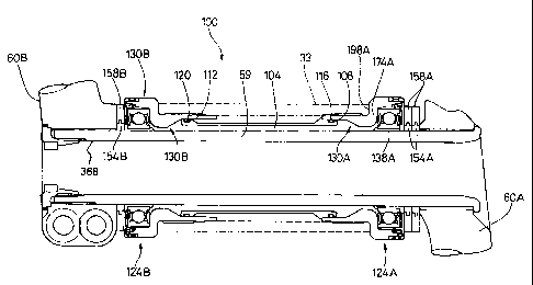
Fig. 2 is a rear cross-sectional view of a particular embodiment of a bottom
bracket
assembly 100 according to the present invention, and Fig. 3 is an exploded
view of
bottom bracket assembly 100. As shown in those figures, bottom bracket
assembly 100
comprises bottom bracket 33, a dust tube 104 disposed within bottom bracket
33,
wherein dust tube 104 includes annular grooves 108 and 112 at the opposite
ends
thereof, O-ring seals 116 and 120 fitted within annular grooves 108 and 112,
respectively, and adapter assemblies 124A and 124B fitted to the ends of
bottom
bracket 33 and dust tube 104. Adapter assemblies 124A and 1248 are used in
part to
position axle 59 laterally within bottom bracket 33 so that front sprockets 62
are
properly aligned with rear sprockets 56. Such positioning allows front and
rear
derailleurs 70 and 74 to operate chain 66 in a satisfactory manner.
As shown more clearly in Figs. 3 and 4, in this embodiment adapter assembly
124A
comprises an adapter member 130A, a bearing ring 134A, a bearing unit 138A, a
seal
ring 142A, a seal guard I46A, an O-ring 150A, two ring-shaped spacers 154A,
and two
soft urethane rinb shaped spacer covers 158A that fit around the outer
peripheral
surfaces of spacers 154A as shown in Fig. 2. Similarly, as shown. in Fig. 3,
adapter
assembly 1248 comprises an adapter member 130B, a bushing in the form of a
bearing
ring 134B, a bearing unit 138B, a seal ring 142B, a seal guard 146B, an O-ring
150B,
one ring-shaped spacer 154B, and a soft urethane ring-shaped spacer cover 158B
that
fits around the outer peripheral surface of spacers 154B. Spacers 154A and
154B help
to set the lateral position of axle 59 as shown in Fig. 2. Tn this embodiment
there are
two spacers 154A on the right side of bottom bracket assembly 100 and only one
spacer
on the left side of bottom bracket assembly 100. Thus, axle 59, crank arms 60A
and
60B and sprockets 62 are shifted slightly to the right relative to hottom
bracket 33.
The adapter assemblies 124A and 124B are constructed the same except for the
number
of spacers, and they operate in the same manner, so only the details of the
components
of adapter assembly 124A will be described in detail. As shown more clearly in
Fig. 4,
CA 02421136 2003-03-05
adapter member 130A comprises a smaller diameter tubular portion 162A having a
threaded outer peripheral surface 166A and a thickened inner portion 170A, a
radially
outwardly extending side wall 174A, and a larger diameter portion 178A having
an
inner peripheral surface 182A and an outer peripheral surface 186A forming a
tool
engaging surface 190A. When adapter assembly 124A is in the assembled state,
threaded outer peripheral surface 166A of smaller diameter portion 162A
completely
screws into a threaded inner peripheral surface 194A (Fig. 3) of bottom
bracket 33 until
side wall 174A of adapter member 130A abuts against a side edge 198A of bottom
bracket 33 as shown in Fig. 2. Thus, in this embodiment there are no exposed
portions
of the threaded outer peripheral surface 166A.
Bearing ring 134A comprises a tubular portion 200A and a radially outwardly
extending side wall 204A. When adapter assembly 124A is in the assembled
state,
bearing ring 134A contacts the inner peripheral surface 182A of larger
diameter portion
178A of adapter member 130A, and side wall 204A abuts against an abutment 208A
formed on inner peripheral surface 182A. In this embodiment, bearing ring 134A
is
formed of a nonmetallic material such as POM plastic.
In this embodiment, bearing unit 138A is a conventional sealed bearing unit
comprising
an inner bearing race 212A, an outer bearing race 216A, a plurality of ball
bearings
220A disposed between inner bearing race 212A and outer bearing race 216A, and
annular side covers 224A. When adapter assembly 124A is in the assembled
state, outer
race 216A contacts bearing ring 134A. Since bearing ring 134A is formed of a
nonmetallic material, squeaking and other undesirable noises caused by the
contact
between these two components are minimized or eliminated. Of course, bearing
ring
134A could be formed of any material that suits the application or for cost
reasons.
Seal guard 146A functions as a support for seal ring 142A and O-ring 150A, and
it
comprises an annular base member 230A, an inner tubular member 234A and an
outer
tubular member 238A. In this embodiment, seal guard 146A is formed of a
nonmetallic
6
CA 02421136 2003-03-05
material such as POM plastic. Inner tubular member 234A extends from a
radially inner
side surface of base member 230A and, in this embodiment, extends from a
radially
innermost edge 242A of base member 230A to form a radially inner peripheral
surface
or inner ledge 246A. When adapter assembly 124A is in the assembled state,
inner
ledge 246A contacts and supports inner bearing race 212A of bearing unit 138A.
A
protuberance 248A extends radially outwardly (approx. 0.1 mm in this
embodiment)
from the free edge 249A of inner tubular member 234A to lock bearing unit 138A
in
position on inner tubular member 234A. Since seal guard 146A is formed of a
nonmetallic material, squeaking and other undesirable noises caused by the
contact
between these two components are minimized or eliminated. Of course, seal
guard
146A could be formed of any material that suits the application or for cost
reasons.
Outer tubular member 238A extends from a radially outer side surface of base
member
230A and, in this embodiment, is spaced apart from a radially outermost edge
250A of
base member 230A to form a radially outer peripheral surface or outer ledge
254A.
When adapter assembly 124A is in the assembled state, outer ledge 254A
contacts and
supports seal ring 142A and the outer bearing race 216A of bearing unit 138A.
Thus,
bearing unit 138A is sandwiched between inner ledge 246A and outer ledge 254A.
While inner tubular member 234A and outer tubular member 238A extend from the
same side of base member 230A in this embodiment, it is not necessary for them
to do
so.
In this embodiment, seal ring 142A functions as an outer seal, and it is a
generally L-
shaped ring member having a base portion 258A and a radially outwardly
extending lip
portion 262A that forms an acute angle with base portion 258A. Base portion
258A
contacts and is supported by outer ledge 254A, and lip portion 262A contacts
the inner
peripheral surface 128A of adapter member 130A. Of course, seal ring 142A may
take
many different forms, and there need not be direct contact between the
components. O-
ring 150A functions as an inner seal, and it is disposed at the radially inner
edge 242A
of base member 230A opposite inner tubular member 234~A. When adapter assembly
7
CA 02421136 2003-03-05
124A is in the assembled state, O-ring 150A contacts axle 59. Seal ring 142A
and O-
ring 150A in combination prevent contaminants from entering the space
containing
bearing unit 138A more advantageously than prior art sealing structures.
Fig. 5 is a detailed cross sectional view of a bearing ring 134A' that
represents an
alternative embodiment of the bearing ring 134A shown in Fig. 4. As with
bearing
ring134A, bearing ring 134A' comprises a tubular portion 200A' and a radially
outwardly extending side wall 204A'. However, in this embodiment a centrally
disposed bushing protuberance 260A extends radially inwardly from tubular
portion
200A for contacting outer bearing race 216A when adapter assembly 124A is in
the
assembled state. If bearing unit 138A is tilted for some reason as shown by
the broken
lines in Fig. 5, such as if bottom bracket 33 is bent as a result of a
manufacturing defect
or a collision, then bushing protuberance 260A accommodates such tilting.
Although
bushing protuberance 260A has a trapezoidal shape in this embodiment, it could
have a
spherical or other shape to perform the same function
As shown in Fig. 3, right side crank arm 60A comprises a crank arm body 300,
an axle
mounting boss 304 having an axle mounting opening 308 with a splined inner
peripheral surface 312, a pedal mounting boss 316 having a pedal mounting
opening
320 with a threaded inner peripheral surface 324, and four sprocket mounting
arms 328
extending radially outwardly from axle mounting boss 304. In this embodiment,
each
sprocket mounting arm 328 has three sprocket mounting openings 328A, 328B and
328C for mounting three front sprockets.
As shown in Figs. 6 and 7, left side crank arm 60B comprises a crank arm body
330, an
axle mounting boss 331 having an axle mounting opening 332 with a splined
inner
peripheral surface 333, and a pedal mounting boss 334 having a pedal mounting
opening 335 with a threaded inner peripheral surface 336. In this embodiment,
axle
mounting boss 311 includes a first mounting ear 337 spaced apart from but in
close
proximity to a second mounting ear 338. First mounting ear 337 includes an
unthreaded
CA 02421136 2003-03-05
fastener opening 339 and a threaded fastener opening 340, and second mounting
ear
338 includes an unthreaded fastener opening 341 and a threaded fastener
opening 342.
A crank arm bolt 343 having a threaded shank 344 and a head 345 extends
through
unthreaded fastener opening 339 in first mounting ear 337 and screws into
threaded
opening 342 in second mounting ear 338 such that head 345 abuts against first
mounting ear 337. Similarly, a crank arm bolt 346 having a threaded shank 347
and a
head 348 extends through unthreaded fastener opening 341 in second mounting
eax 338
and screws into threaded opening 340 in first mounting ear 337 such that head
348
abuts against second mounting ear 338. Crank arm bolts 343 and 346 thus
tighten first
mounting ear 337 and second mounting ear 338 towards each other for clamping
axle
mounting boss 331 around axle 59 as discussed below.
Axle 59 has an axle body 348 including a first end portion 350 and a second
end
portion 354. First end portion 350 has a plurality of circumferentially
disposed splines
358 that protrude radially outwardly relative to an outer peripheral surface
362 of axle
body 348 for engaging the splined inner peripheral surface 312 o.f axle
mounting boss
308 of crank arm 60A as shown in Fig. 2. A radially outwardly extending flange
366 is
disposed at the extreme end of end portion 350 for abutting against the
laterally outer
surface of axle mounting boss 308 of crank ann 60A. Second end portion 354 of
axle
59 has a threaded inner peripheral surface 368 (Fig. 2) and a plurality of
circumferentially disposed splines 370 fox engaging the splined inner
peripheral surface
333 of axle mounting boss 331 of crank arm 60B. In this embodiment, splines
370 do
not extend radially outwardly relative to the outer peripheral surface 362 of
axle body
348. Instead, the splines 370 are flush with the outer peripheral surface of
362 of axle
body 348. Second end portion 354 and axle body 348 thus are capable of freely
passing
through opening 308 in crank axle mounting boss 304 of crank arm 60A and
though
dust tube 104 and adapter assemblies 124A and 124B so that second end portion
354 of
axle 59 extends into opening 332 in crank axle mounting boss 331 of crank arm
60B
and flange 366 abuts against mounting boss 304 of crank arm 60A.
9
CA 02421136 2003-03-05
An axle bolt 380 screws into the threaded inner peripheral surface 368 of
second end
portion 354 of axle 59. As shown in Figs. 2, 3, 8 and 9, axle bolt 380
comprises a bolt
body 384 having a threaded outer peripheral surface 388 and an inner
peripheral surface
392 defining an opening 396. A plurality of (e.g., eight) splines 400 are
circumferentially disposed on the inner peripheral surface 392 of an end 402
of bolt
body 384, and a flange 404 with a knurled outer peripheral surface 408 extends
radially
outwardly from end 402 of bolt body 384. In this embodiment, each spline 400
comprises an arcuate projection 412 adjacent to a groove 416.
A tool 450 shown in Figs. 8 and 10 is provided for screwing axle bolt 380 into
the
threaded inner peripheral surface 368 of second end portion 354 of axle 59.
Tool 450
comprises a tool body 454 and a tool operating member 460. Tool body 454
comprises
a splined portion 458 and a stepped portion 459 disposed between splined
portion 458
and tool operating member 460, wherein stepped portion 459 extends radially
outwardly from splined portion 458. Splined portion 458 comprises a plurality
of (e.g.,
eight) circumferentially disposed splines, each comprising a radially
outwardly
extending spline projection 459 adjacent to a spline groove 460. Tool
operating
member 460 extends radially outwardly from stepped portion 459 of tool body
454. In
this embodiment, tool operating member 460 has a disk shape, and tool body 454
extends from a side surface 470 of tool operating member 460. A gripping rim
474
having a knurled outer peripheral surface 478 is disposed at a radially
outermost portion
of tool operating member 460 such that gripping rim 474 extends laterally from
a side
surface 478 of tool operating member 460.
To assemble axle 59 to bottom bracket 33, dust tube 104, O-ring seals 116 and
120 and
adapter assemblies 124A and 124B are mounted to bottom bracket 33. Axle 59 is
passed through opening 308 in crank axle mounting boss 304 of crank arm 60A
and
though adapter assemblies 124A and 124B and dust tube 104 so that second end
portion
354 of axle 59 extends into opening 332 in crank axle mounting boss 331 of
crank arl-n
60B and flange 366 abuts against mounting boss 304 of crank arm 60A. Axle bolt
380
CA 02421136 2003-03-05
is then screwed into the threaded inner peripheral surface 368 of axle 59
using tool 450
by engaging splined portion 458 of tool 450 with splines 400 of axle bolt 380
and by
gripping and turning gripping rim 474 until the desired amount of play exists
between
crank arms 60A and 60B and spacers 154A and 154B. Thereafter, bolts 343 and
346 are
tightened while axle mounting boss 331 of crank arm 60B abuts against flange
404 of
axle bolt 380 to set the final position of crank arm 60B and thereby the play
between
crank arms 60A and 60B and spacers 154A and 154B.
While the above is a description of various embodiments of the present
invention,
further modifications may be employed without departing from the spirit and
scope of
the present invention. For example, the size, shape, location or orientation
of the
various components may be changed as desired. Components that are shown
directly
connected or contacting each other may have intermediate structures disposed
between
them. The functions of one element may be performed by two, and vice versa. It
is not
necessary for all advantages to be present in a particular embodiment at the
same time.
Every feature which is unique from the prior art, alone or in combination with
other
features, also should be considered a separate description of further
inventions by the
applicant, including the structural andlor functional concepts embodied by
such
feature(s). Thus, the scope of the invention should not be limited by the
specific
structures disclosed or the apparent initial focus on a particular structure
or feature.
11