Note: Descriptions are shown in the official language in which they were submitted.
CA 02421152 2003-03-04
WO 02/20371 PCT/US01/27616
PRODUCT DISPENSER
BACKGROUND OF THE INVENTION
The present invention relates to a dispenser for housing and dispensing
product, such
as miniature batteries including zinc air cells used in hearing aids. As used
herein, "battery"
means one or more cells.
Handling of miniature batteries is difficult because of their small size.
Handling of
miniature batteries is typically required in order to remove the batteries
from their
packaging, to insert the batteries in the proper orientation into a device,
and, in the case of
air cells, to remove any individual tabbing associated with the cell prior to
use. Tabbing is
nonnally associated with metal air cells such as zinc air cells, to limit the
ingress of oxygen
into the cell until such time as the cell is placed into service. The tab also
functions to limit
the transport of water vapor in or out of the cell and limits the ingress of
carbon dioxide into
the cell. Typically, the tab comprises an adhesive material covering one or
more air ports.
Upon removal of the tab, the ports are exposed to the oxygen of the ambient
environment,
thereby enabling the cell to be activated. The challenge of handling miniature
batteries is
exacerbated in the event the user suffers from reduced dexterity, poor vision
or other
physical infirmity.
Efforts to address some of these issues are found in the art. For example,
U.S. Pat.
No. 6,039,185 discloses a device for inserting a hearing aid battery into a
hearing aid. The
device comprises so-called "petals" with an air cell residing on each petal.
The cells are
individually tabbed, and each tab is then adhered to the petal. The cell is
inserted into the
hearing aid by gripping the inserter and bringing the appropriate petal up
close to the
hearing aid battery door to enable the cell to be engaged within the door. The
cell is then
separated from the inserter using a wiping motion, purportedly leaving the tab
adhered to
1
CA 02421152 2003-03-04
WO 02/20371 PCT/US01/27616
the petal. The method of separating the cell from its associated tab and the
inserter as
disclosed in the'185 patent places stresses on the hearing aid device,
presenting the
potential for damage to the device.
Typical packaging for miniature zinc air cells presents further problems.
Common
packaging for miniature zinc air cells is disclosed for example in US Pat. No.
4,593,700.
The packaging disclosed therein consists of a thermoformed or molded blister
rotatably
attached to a paperboard card. The blister comprises multiple compartments
each
containing a battery. A battery is dispensed from the package by rotating the
blister to align
a loaded compartment with a trap door accessible in the back of the card. The
trap door can
come open during transport and batteries will fall out. The trap door becomes
weak and
ineffective after multiple uses. The base of the dial can also separate or
pull away from the
card allowing batteries to fall out. Finally, the consumer must still handle
the battery to
remove the tab, properly orient the cell in connection with the device
terminals and insert
the cell into the device once the battery has been removed from the package.
Some consumers use a separate tool to assist them in loading miniature
batteries into
devices. This tool consists of a magnet on the end of a wand. The tool can be
'easily
misplaced and provides little aid in removing the individual tabbing
associated with
common zinc air cells.
Handling of other small products including but not limited to pharmaceuticals
such
as pills, foodstuff such as candy, hardware such as screws, and the like can
be equally
difficult because of their size, particularly for those users suffering from
reduced dexterity,
poor vision or other physical infirmity. While the within invention is
illustrated in
connection with miniature cells, and in particular in connection with
miniature zinc air cells,
it will be appreciated that the within invention can also be utilized in
connection with the
transport, storage and dispensing of such other small products. As used
herein, the term
2
CA 02421152 2006-11-14
t
"product" is not limited to miniature cells or batteries, and fully
comprehends such other
small products as those identified above.
It is therefore a first aspect of the present invention to provide a product
dispenser
that acts as both a structural package for housing and transporting product
and a dispenser
for removing product from the package and an inserter for manipulating and
orienting
product into a device or other end use location.
It is also an aspect of the present invention to provide a product dispenser
that
removes any direct handling of product prior to its insertion into a device or
other end use
location.
It is a further aspect of the present invention to provide a product dispenser
that
obviates the need for direct handling of tab material in the case of a metal
air cell such as a
zinc air. cell.
It is a further aspect of the present invention to provide a product dispenser
that both
activates and dispenses air cells such that the user does not have to handle
the cells either
before or after inilertion into a device.
Another aspect of the present invention is to provide a product dispenser that
eliminates the need for additional tools to handle and orient product for
insertion or
placement for end use.
Another aspect of the present invention is to provide a product dispenser that
avoids
unintended dispensing from the dispenser.
Another aspect of the present invention is to provide a refill base cartridge
for a
product dispenser.
Another aspect of the present invention is to provide a product dispenser that
optionally allows the user to attach a refill base after removal of a spent
base carhidge.
3
CA 02421152 2006-11-14
Another aspect of the present invention is to provide a product dispenser that
allows
the consumer to store used product for disposal or material recovery purposes.
The foregoing and additional aspects of this invention will become fully
apparent from
the following description and the accompanying drawings.
SLTMMARY OF THE INVENTTON
The present invention provides for a product dispenser that is easy to use for
storing
and dispensing product, such as miniathue batteries. The dispenser of the
within invention
obviates the need to handle the product at any point during the dispensing
process or during
the insertion or placement process of the product for its end use. To achieve
this and other
advantages, and in accordance with the purposes of the present invention as
embodied and
described herein, the present invention provides for a product dispenser
comprising a cover
and a base, each rotatable with respect to the other about a common axis, a
retractable push
element slidably engaged along an opening in the roof of the cover, and a
landing. The
cover further comprises a wall and a wall opening. The roof opening, wall
opening and
landing are aligned to enable product to be advanced from the interior of the
cover, through
the wall opening and onto the landing by the push element. The landing is
designed to
accept and removably retain imdividual product. The push element slides in
opposing
d.irections along the roof opening to engage product and advance product from
the interior
of the cover onto the landing. The base cooperates with the cover assembly to
house the
product and provides locations for securing product prior to dispensing.
In another embodiment, the cover fiuther comprises a rib. The nb is secured to
the
inner surface of the roof such that when the cover is assembled with the base,
the product is
under pressare from the rib allowing the nl) to further secure the product to
the base during
4
CA 02421152 2008-10-27
transport and storage. In another embodiment, the rib functions to apply
pressure so as to
seal an air cell to a gasket prior to dispensing.
In another embodiment, the cover is removably attached to the base allowing
the base
to be disposed of and a replacement base with additional product to be jointed
with the cover.
In another embodiment the bottom side of the base comprises a storage area for
storing used product for disposal or material recovery purposes. The entire
dispenser could
be processed for material recovery or otherwise recycled. In the event the
cover and the base
are separable, the base alone could be processed for material recovery or
otherwise recycled.
In another embodiment the cover is made of see-through material and the push
element or base or both can be color coded to indicate various product
characteristics, such
as size.
In a broad aspect, the invention seeks to provide a dispenser for
transporting, housing
and dispensing product, the dispenser comprising a cover comprising a wall, a
wall opening,
a roof and a longitudinal opening in the roof, a push element slidably engaged
along the roof
opening, a base and a landing for removably retaining product. The cover and
the base are
rotatable with respect to each other about a common axis, characterized in
that the roof
opening, the wall opening and the landing are alignable to enable the product
to be advanced
from the interior of the cover through the wall opening and onto the landing
by the push
element and that the push element is slidably engaged along the longitudinal
axis of the roof
opening.
The invention in a further aspect provides a dispenser for transporting,
housing and
dispensing product, the dispenser comprising a cover comprising a roof
5
CA 02421152 2008-10-27
and an opening in the roof, a push element slidably engaged along the roof
opening, a base
and a landing for removably retaining product, wherein the cover and the base
are rotatable
with respect to each other about a common axis.
These and other features, advantages, and aspects of the present invention
will be
further understood and appreciated by those skilled in the art by reference to
the following
specification, claims, and appended drawings.
BRIEF DESCRIPTION OF DRAWINGS
FIGURE 1 is a view of a product dispenser according to the within invention.
FIGURE 2A is a view of a cover of a product dispenser according to the within
invention.
FIGURE 2B is another view of the cover of Figure 2A.
FIGURE 2C is a view of an alternate cover of a product dispenser according to
the
within invention.
5a
CA 02421152 2006-11-14
FIGURE 3A is a view of a push element of a product dispenser according to the
within invention.
FIGURE 3B is another view of the push element of Figure 3A.
FIGURE 3C is a side view of the push element of Figures 3A and 3B.
FIGURE 4A is a front view of a cover and push element of a product dispenser
according to the within invention.
FIGURE 4B is a section view of the cover and push element of Figure 4A.
FIGURE 5A is a view of a base of a product dispenser according to the within
invention.
FIGURE 5B is a side view of the base of Figure 5A.
FIGURE 5C is a section view of the base of Figure 5B.
FIGURE SD is another view of the base of Figure 5A.
FIGURE 6A is a view of a platform of a product dispenser according to the
within
invention.
FIGURE 6B is a side view of a platform of a product dispenser according to the
within invention.
FIGURES 7A, 7B and 7C illustrate an alternate base of a product dispenser
according to the within invention.
FIGURE 8 illusttates another alternate base of a product dispenser according
to the
within invention.
FIGURE 9 is an exploded view of an alternate embodiment of a product dispenser
according to the within invention.
FIGURE IOA is a view of a cover of the product dispenser of Fig. 9.
FIGURE l OB is another view of the cover of Fig.10A.
FIGURE 11 is a view of a base platform of the product dispenser of Fig. 9.
6
CA 02421152 2003-03-04
WO 02/20371 PCT/US01/27616
FIGURE 12 is a view of one layer of the adhesive product platform of the
product
dispenser of Fig. 9.
FIGURE 13A is a view of a push element of the product dispenser of Fig. 9.
FIGURE 13B is another view of the push element of Fig. 13A.
FIGURE 14A is a view of a base ring of the product dispenser of Fig. 9.
FIGURE 14B is another view of the base ring of Fig. 14A.
FIGUR.E 15 is a view of the product dispenser of Fig. 9.
FIGURE 16A is a view of an alternate embodiment of the push element of a
product
dispenser of Fig. 9.
FIGURE 16B is another view of the push element of FIG. 16A.
FIGURE 17A is a view of an alternate embodiment of the cover of a product
dispenser of Fig. 9.
FIGURE 17B is another view of the cover of FIG. 17A.
DETAILED DESCRIPTION OF THE PREFERRED EMBODIMENTS
The specific embodiments illustrated in the appended drawings and described in
the
following specification are simply exemplary embodiments of the inventive
concept defined
in the appended claims. Hence, specific dimensions and physical
characteristics relating to
specific embodiments disclosed herein are not to be considered as limiting,
unless the
claims expressly state otherwise.
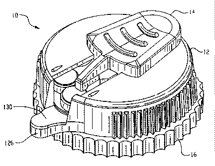
The dispenser 10 of the within invention comprises a cover 12, a retractable
push
element 14, and a base 16. The cover 12 and the base 16 are connected such
that each can
be rotated about a common axis with respect to the other. That is, the cover
can be rotated
while maintaining the base in a stationary position, or, conversely, the base
can be rotated
while maintaining the cover in a stationary position.
7
CA 02421152 2003-03-04
WO 02/20371 PCT/US01/27616
The rotatable cover 12 comprises a roof 121, roof ramps 122, a roof opening
123, a
wal1124, a wall opening 125, a landing 126, and flexible snap-hook connectors
127a, 127b
and 127c. In a preferred embodiment, the cover 12 is made from a readily-
available,
polycarbonate-based material such as Lexan 143R resin manufactured by GE
Plastics and
available from Polymerland Service Center, Pittsburgh, PA 15264. It should be
appreciated that other durable materials may be used in producing the cover
12. In addition,
the cover 12 may further include a rib 128 as shown in figure 2C.
The roof ramps 122 protrude from the outer surface 129 of the roof 121
adjacent to
the roof opening 123. The roof ramps 122 are angled protrusions that
frictionally engage the
push element 14 and create a transitional stopping action for the push element
as it is
extended. The ramps 122 aid in providing a fluid and controlled motion for the
push
element 14 that encourages controlled movement of product toward the landing
126. The
ramps 122 also aid in maintaining the push element in a fully extended
position.
Alternatively, a third roof ramp 122a may be positioned on the outer surface
129 of the roof
121 such that the third roof ramp aids in keeping the push element in place
while fully
retracted. It will be appreciated that a wide variety of shapes and locations
can be utilized
for the roof ramps without departing from the teachings of the within
invention.
The roof opening 123 is coincidental with the wall opening 125 and the landing
126
is secured to the cover 12 at a location adjacent to the wall opening 125.
Product passes
through the wall opening 125 from the interior of the cover 12 onto the
landing 126.
Product aligned at the wall opening 125 for such transition is said to be
located in the
product dispensing position.
The landing 126 is preferably inclined as shown in Figure 4B to further aid in
transitioning the product from the interior of the cover 12 to the landing
126. The landing
126 optionally comprises a magnetic component 130 secured to the landing 126
via a
8
CA 02421152 2006-11-14
pressure sensitive adhesive. The magnetic component 130 aids in controlli.ng
and removably
main.taiining metallic products such as miniature batteries on the landing
126. Alterna.tively,
as dictated by the product, other surfaces or materials, such as velcro or
adhesives, may be
utilized for controlling and removably maintaining products on the landing 126
as will be
appreciated by those skilled in the art. These alternate surfaces or
ma.terials may comprise
the entire landing 126 or may be secured to the landing 126 via an adhesive or
other
securing method. Further, the magnetic component 130 can be planar or
otherwise shaped,
and may be exposed or embedded within the landing. Where product use and
placement
permit, the landing 126 may farther include a stop wall (not shown) at its
distal end to
io further control the forward motion of the product as it transitions from
the interior of the
cover 12 to the landing 126. It should be appreciated that the landing 126 may
be integral to
the cover 12 or the base 16 or may be a separate component connected to either
the cover 12
or the base 16.
The snap hook coimectors 127a,127b and 127c extend from the inner surface of
the
roof 121 and are positioned at 90 degree intervals around the roof opening
123. The
connectors fiuther comprise flexible angled lead-in sarfaces 131 and flexible
tension-
providing surfaces 132. The lead-in sarfaces 131 interact with the inner
sarface of the base
opening during connection of the base with the cover, causing the snap hook
connectors to
flex inwardly, as will be more fatly explained below. The tension-providing
surfaces 132
2o maintain tension contact with the base upon completion of the connection
process and the
outward return flex of the snap hook comectors 127a,127b and 127c. The number
and
positioning of the snap hook connectors is a matter of design choice and can
be varied
without departing from the scope of the within invention.
One of the snap hook connectors further comprises a rib 133. The n`b 133 is
positioned such that when the cover 12 or the base 16 is rotated, a stop point
is created once
9
CA 02421152 2006-11-14
the rib 133 engages a base turret groove 173. Each such stop point aligns a
product and/or a
product dispensing position with the wall opening 125 of the cover 12.
The outer surface of the cover wall 124 may be all or partially ribbed as
illustrated
or otherwise textured to provide a grip for the cover 12 during relative
motion beiween the
cover 12 and base 16. Additional gripping can be provided by extending the
upper surface
of the cover 12 outwardly beyond the cover wall 124 at one or more locations.
The push element 14 comprises a thumbpiece 141 having gripping ribs 142 or
alternatively a textured surface secured to the upper surface of the
thumbpiece 141 for
gripping the push element 14. In a preferred embodiment, the push element is
molded from
TM
a polystyrene material such as Styron 6075 manufactured by Dow Plastics and
available
from General Polymers, Columbus, OH 43216.
The push element 14 further comprises a projection 143. The projection 143
extends over at least a portion of the product located in the product
dispensing position
during transport and storage of the dispenser 10, to aid in maintaining the
product in this
position. The proj ection 143 further aids in controlling the movement of
product during
transition from the interior of the cover 12 onto the landing 126, and in
maintaining the
position of individual product on the landing 126. Optionally, a lip 144 is
located on the
bottom surface of the projection 143 which aids in securing individual product
in the
product dispensing position and in position on the landing 126.
The push element 14 further comprises two slide rails 145 and a center radder
146,
both secured to the lower surface of the thumbpiece 141. The radd.er 146 is
aligned with a
base turret opening 172 whenever the snap hook connector rib 133 is engaged
with a base
turret groove 173 to create a stop position for relative motion between the
cover 12 and the
base 16. Such alignment is required to allow the push element to be extended.
When the
push element 14 is fiilly retra:cted, the rudder 146 does not occupy the
aligned base tarret
CA 02421152 2003-03-04
WO 02/20371 PCT/US01/27616
opening 172 and the base 16 and the cover 12 are free to move with respect to
each other
between stop positions. This fitlly retracted position will be referred to
herein as the first
position of the push element 14. At a stop position the push element 14 can be
partially or
fully extended, causing the rudder 146 to occupy the aligned base turret
opening 172
thereby preventing motion between the base 16 and the cover 12 to an alternate
stop
position. This partial or full extension position will be referred to herein
as the second
position of the push element 14.
The rudder 146 further comprises a scraper 147 positioned at the front of the
rudder.
The scraper 147 is designed to separate individual product from the product
dispensing
position by interposing the scraper 147 between the product and the product
dispensing
position upon extension of the thumbpiece 141. In the case of an air cell,
interposing the
scraper 147 between the cell and the product dispensing position untabs the
cell, allowing
air ingress and cell activation.
It should be appreciated that the projection 143, the lip 144 and the scraper
147 may
all be contoured to shape according to the product contained within the
dispenser without
departing from the teachings herein.
The slide rails 145 of the thumbpiece 141 comprise snap hooks having angled
surfaces 148a and flat surfaces 148b. The angled surfaces 148a allow a portion
of the push
element 14 to pass through the roof opening 123 for snap connection of the
push element
with the cover 12. The angled surfaces 148a contact the sides of the roof
opening during
connection causing the snap hooks to flex inwardly. Once the angled surfaces
148a have
cleared the roof opening 123, the snap hooks retract, thereby engaging the
inner surface of
the cover and the flat surfaces 148b of the snap hooks, enabling the push
element to slidably
extend and retract along the roof opening 123.
11
CA 02421152 2003-03-04
WO 02/20371 PCT/US01/27616
The push element 14 further comprises two stop walls 149 positioned on the
lower
surface of the thumbpiece 141. The stop walls 149 define a stop position for
the fully
extended push element 14 upon contacting the inside surface of the cover
wal1124. In an
alternative embodiment, the stop position for the fully extended push element
14 can be
provided by extending the slide rails 145 so that they contact the inside
surface of the cover
wall 124 when the push element 14 is fully extended.
The base 16 comprises a lower tier 161, an upper tier 162 and a hollow center
163.
The lower tier comprises an outer wall 164 and an upper surface 165. The upper
tier further
comprises an outer wa11166 and an upper surface 167. In a preferred
embodiment, the base
is molded from Styron 6075 as described above.
The lower tier upper surface 165 is sized to accommodate the width of the
cover
wall 124. When joined, the bottom surface of the cover wall 124 is in contact
with the
lower tier upper surface 165 and a portion of the inner surface of the cover
wall 124 is in
contact with the upper tier outer wall 166.
All or a portion of the lower tier outer wall 164 may be partially ribbed as
shown or
otherwise textured to provide a grip for the base 16 during relative motion
between the
cover 12 and base 16. Extensions (not shown) from the base may be included to
provide
handles to aid in separating the base 16 from the cover 12. The lower tier
outer wall 164
may optionally include an indicator such as an arrow (not shown). Aligning the
landing 126
with the indicator during connection of the cover and base also aligns the
snap hook
connector rib 133 of the cover 12 with a base turret groove 173, facilitating
the connection.
The hollow center 163 further comprises a turret partition 169 defined by a
beveled
edge 170 and turret structures 171 extending above the upper tier upper
surface 167. The
turret structures 171 are separated by turret openings 172. The openings 172
are sized to
permit the rudder 146 to occupy an opening during extension of the push
element 14 in its
12
CA 02421152 2006-11-14
second position. The lead in surfaces 131 of the cover snap hook connectors
127a-c contact
the turret partition 169 during connection of the cover and base, causing the
cover snap
hook connectors to flex inwardly. Upon encountering the beveled edge 170 of
the base
hollow center 163, the snap hook connectors retract, allowing the tension-
providing surfaces
132 of the cover snap hook connectors to contact the beveled edge and thereby
secure the
cover and base together.
The turrets 171 further comprise grooves 173 extending along the length of the
partition 169. Insertion of the snap hook rib 133 of the cover into one of the
turret grooves
173 defines a stop position whereby product located at the product dispensing
position is
lo aligned with the cover wall opening 125 and the landing 126.
Product is afftxed to the upper tier upper surface 167 via adhesive or other
suitable
means. In a preferred embodiment of the within invention, zinc air msniatue
cells 174 are
exemplified as the product, and are adhered to the base using an adhesive
platform 175.
The platform comprises at least one adhesive layer. In a preferred
em:bodiment, the
platform comprises a lower adhesive layer 176, amid adhesive layer 177, an
upper adhesive
layer 178, a foam tape layer 179 sandwiched between the lower and mid adhesive
layers, a
mylar film layer 180 sandwiched between the mid and upper adhesive layers, and
a
polyester overcoat layer 1811ocated atop the upper adhesive layer. The lower
and mid
adhesive layers with a foam layer sandwiched in between are available as a
single product,
TM
f
rom Label Tecbnologies Inc., Spec. #4105 (double sided closed cell foam with
acrylic
adhesive), Suwanee, Georgia. The mylar film layer and upper adhesive layer are
also
TM
available as a single product from Label Technologies Inc., Spec. #72907
(polyolefin with
R-143 adhesive). The polyester overcoat layer is available from Label
Technologies Inc.,
TM
Spec. #2216 (interfilm metalized polyester). Alterna.ting cutouts 175a are
provided in the
overcoat layer 181 to expose portions of the underlying adhesive layer 178.
The air cells
13
CA 02421152 2006-11-14
174 are placed upon the exposed adhesive portions to seal their associated air
ports until
such time as the cell is transferred from the imterior of the cover to the
landing. In a
preferred embodiment, the cutouts are larger than the diameter of the cells,
such that the
cells do not come into direct contact with the overcoat layer. It will be
appreciated that the
overcoat layer 181 is an optional feature designed primarily to prevent the
accumulation of
dust and other debris on the upper adhesive layer 178 and to provide an
aesthetically
pleasing appearance. As such, it will be appreciated that other materials with
an
aesthetically appealing appearance, adequate adhesion to the underlying
adhesive layer, and
a surface that will avoid the accumulation of dust and debris could be used in
place of the
polyester overcoat layer181.
In this embodiment, the air cells are not individually tabbed, thereby
obviating the
expense associated with such an operation. Further, the tabbing material
remams with the
dispenser when the cell is dispensed, avoiding the need to handle or otherwise
dispose of an
individual tab. It will be appreciated, however, that the dispenser of the
within invention
can be utilized with individually tabbed air cells. In such an embodiment, the
tab is
mechanically or adhesively joined to the base. The cell is then separated from
the tab when
the thumbpiece scraper is inserted between the tab and the cell. The cell is
then advanced
from the interior of the cover onto the landing while the tab remains attached
to the
dispenser base.
Individual tabbing of air cells can also be avoided using the within invention
where
one surface of a gasket sealing material is affixed with an appropriate
adhesive to the upper
tier surface 165 of the base. The opposing gasket surface then directly
contacts the bottom
of the cell. The cells are then sealed by placing sufficient downward pressure
on the top of
the cell from the cover rib 128 to effectively limit the amount of air mgress
until such time
14
CA 02421152 2003-03-04
WO 02/20371 PCT/US01/27616
as the cell is advanced to the product dispensing position. The pressure also
secures the
cells in position on the base until dispensed.
Other techniques and methods for adhering product to the base may also be used
without departing from the teachings of the within invention. Adhesive to
secure product
may be applied as a surface coating to the upper tier upper surface 165, or
alternatively,
may be applied in discrete locations to coincide with the number and spacing
of product on
the upper surface of the upper tier. Adhesives appropriate to the type of
product can be
selected as is known in the art.
The underside of the base 16 optionally comprises a series of support ribs
182. In an
alternate embodiment, the ribs define one or more storage compartments 183 for
spent
product. Where individual compartments are defined by such ribs, spent product
can be
secured in position using an interference fit between the product and the
storage
compartment. Alternatively, spent product can be secured into position by
sealing the
compartments with a rotatable covering 184 having an opening 185, as
illustrated in figures
7a-c. The opening 185 could be aligned with an individual storage compartment
to allow the
spent air cells to pass through the opening into the compartment 183. In the
event support
ribs are not utilized, the void volume of the base can still function as a
repository for spent
product as illustrated in figure 8.
To operate the dispenser from the starting position, the push element 14 is
placed in
the first position, the fully retracted position. The cover 12 and base 16 are
then rotated
with respect to each other until a stop position is reached where product is
located in the
product dispensing position. The push element is then advanced to the fully
extended
position, causing the product to transition from the product dispensing
position to the
landing. At this point, the dispenser 10 may be used as a handle to orient the
product and
insert it correctly into a device.
CA 02421152 2003-03-04
WO 02/20371 PCT/US01/27616
In an alternate embodiment of the dispenser of the within invention as
depicted in
Figures 9 through 17B, the dispenser 210 of the within invention comprises a
cover 212, a
retractable push element 214 and a base 216. The cover 212 and the base 216
are connected
such that each can be rotated about a coinmon axis with respect to the other.
That is, the
cover can be rotated while maintaining the base in a stationary position, or,
conversely, the
base can be rotated while maintaining the cover in a stationary position.
The rotatable cover 212 comprises a roof 321, a roof opening 322, a wa11323, a
wall
opening 324, a landing 325 and cover snap hook connectors 326. The cover 212
can be
made from a readily-available, polycarbonate-based material such as Lexan
143R resin
manufactured by GE Plastics and available from Polymerland Service Center,
Pittsburgh,
PA 15264. It should be appreciated that other durable materials may be used in
producing
the cover 212.
The roof opening 322 is coincidental with the wall opening 324 and the landing
325
is secured to the cover 212 at a location adjacent to the wall opening 324.
Product passes
through the wall opening 324 from the interior of the cover 212 onto the
landing 325.
Product aligned at the wall opening 324 for such transition is said to be
located in the
product dispensing position.
The landing 325 is preferably inclined as shown to further aid in
transitioning the
product from the interior of the cover 212 to the landing 325. The landing 325
optionally
comprises a magnetic component 327 embedded within the landing. Alternatively,
the
magnet can be secured to the landing surface via a pressure sensitive adhesive
or otherwise
affixed to the landing, as is known in the art. The magnetic component 327
aids in
controlling and removably maintaining metallic products such as miniature
batteries on the
landing 325. Alternatively, as dictated by the product, other surfaces or
materials, such as
velcro or adhesives, may be utilized for controlling and removably maintaining
products on
16
CA 02421152 2003-03-04
WO 02/20371 PCT/US01/27616
the landing as will be appreciated by those skilled in the art. These
alternate surfaces or
materials may comprise the entire landing. Further, the magnetic component 327
can be
planar or otherwise shaped. Where product use and placement permit, the
landing 325 may
further include a stop wall (not shown) at its distal end to further control
the forward motion
of the product as it transitions from the interior of the cover 212 to the
landing 325. It
should be appreciated that the landing 325 may be integral to either the cover
212 or the
base 216 or may be a separate component connected to either the cover 212 or
the base 216.
The snap hook connectors 326 extend inwardly from the inner surface of the
cover
212 and are positioned at regular intervals around the interior perimeter of
the cover 212.
The connectors interact with the base ring 362 during connection of the base
ring with the
cover as will be more fully explained below and maintain tension contact with
the base ring
upon completion of the connection process. The number, shape and positioning
of the snap
hook connectors is a matter of design choice and can be varied without
departing from the
scope of the within invention.
The outer surface of the cover wa11323 may be all or partially ribbed as
illustrated
or otherwise textured to provide a grip for the cover 212 during relative
motion between the
cover 212 and base 216. Additional gripping can be provided by extending the
upper
surface of the cover 212 outwardly beyond the cover wal1323 at one or more
locations.
The push element 214 comprises a thumbpiece 341 having a gripping rib 342 or
alternatively a textured surface secured to the upper surface of the
thumbpiece 341 for
gripping the push element 214. The push element can be molded from a
polystyrene
material such as Styron 6075 manufactured by Dow Plastics and available from
General
Polymers, Columbus, OH 43216, or such other suitable material as is known in
the art.
The push element 214 further comprises a projection 343. The projection 343
extends over at least a portion of the product located in the product
dispensing position
17
CA 02421152 2003-03-04
WO 02/20371 PCT/USO1/27616
during transport and storage of the dispenser 210, to aid in maintaining the
product in this
position. The projection 343 further aids in controlling the movement of
product during
transition from the interior of the cover 212 onto the landing 325, and in
maintaining the
position of individual product on the landing 325. Optionally, a lip 344 is
located on the
bottom surface of the projection 343 which aids in securing individual product
in the
product dispensing position and in position on the landing 325.
The push element 214 further comprises two slide rails 345 and a central
rudder 346
and two side rudders 346a secured to the lower surface of the thumbpiece 341.
When the
rudder 346 aligns with a base platform turret opening 367 in the fully
retracted position of
the push element, the push element 214 can be extended to advance product onto
the
landing 325. Extension of the push element causes the center rudder 346 to
occupy a base
platform turret opening 367, preventing rotation of the base 216 with respect
to the cover
212. When the push element 214 is fully retracted, the rudder 346 does not
occupy a base
platform turret opening 367 and the base 216 and the cover 212 are free to
move with
respect to each other, enabling product to be located in the product
dispensing position.
Movement of the push element 214 is further controlled by upper projections
372 on base
ring 362. When the push element is extended to advance product onto the
landing 325, side
rudders 346a occupy an opening between upper projections 372, thereby
preventing rotation
of the cover and base with respect to each other.
The slide rails 345 maintain a snap connection between the push element 214
and
the cover 212 and cooperate with the surfaces of the roof opening 322 to allow
the push
element to move along the roof opening.
It should be appreciated that the projection 343 and the lip 344 may be
contoured to
shape according to the product contained within the dispenser without
departing from the
teachings herein.
18
CA 02421152 2003-03-04
WO 02/20371 PCT/US01/27616
The slide rails 345 comprise snap hooks to provide a snap connection between
the
push element and the cover 212 while enabling the push element to slidably
extend and
retract along the roof opening 322. The slide rails 345 contact the inside
surface of the cover
wall 323 preventing further extension and defining the fully extended push
element
position.
The base 216 comprises a base platform 361, a base ring 362 and a product
platform
363. The base platform 361 comprises openings 364 at regularly spaced
intervals that
cooperate with extensions 365 on the base ring 362 to provide a snap
connection between
the base platform 361 and the base ring 362. The base platform 161 further
comprises
turret extensions 166 defining turret openings 167 arranged in a concentric
circle, to control
the movement of the push element 214 as explained above.
All or a portion of the base platform 361 may be ribbed as shown or otherwise
textured to provide a grip for the base 216 during relative motion between the
cover 212 and
base 216. Extensions (not shown) from the base may be included to provide
handles to aid
in separating the base 216 from the cover 212.
Product is fixed onto the product platform 363 via adhesive or other suitable
means.
In a preferred embodiment of the within invention, zinc air miniature cells
400 are
exemplified as the product, and the adhesive product platform comprises an
adhesive tab
layer 368, a kill liner layer 369 and an adhesive foam layer 370. The tab
layer 368 has an
adhesive upper surface and comprises precut tab areas 371. Air cells 400 are
positioned onto
the adhesive surface at the tab areas 371, thereby preventing the ingress of
air sufficient to
activate the cells prior to dispensing the cells from the dispenser 210. A
kill liner layer 369
is positioned between the tab layer 368 and the foam layer 370. The function
of the kill
liner layer 369 is to selectively block the upper adhesive surface of the foam
layer 370 from
contacting selected portions of the lower surface of the tab layer 368 and is
shaped
19
CA 02421152 2003-03-04
WO 02/20371 PCT/US01/27616
accordingly. A mylar film suitable for this function can be selected as is
known in the art.
In this way only a portion of the precut tab areas 371 are adhesively secured
to the foam
layer 369 prior to dispensing the cell, enabling a measure of control over the
amount of
force required to separate the cell from the tab as the cell is advanced by
the push element
from the interior of the dispenser to the dispenser landing. The foam layer
and the tab layer
are available from Label Technologies, Suwanee, Georgia.
In an alternate embodiment, the kill liner layer can be eliminated by
selectively
applying an adhesive to only those portions of the upper surface of the foam
layer 370
where adhesive contact with the lower surface of the tab layer 368 is desired.
In another
embodiment, selective application of adhesive is accomplished in only those
portions of the
upper surface of the tab layer 368 where adhesive contact with the product is
desired.
The product platform 363 is further joined to the base platform 361 via the
snap
connection between the base ring 362 and the base platform 361. The base ring
362
comprises a lip about the perimeter to capture the outer perimeter of the tab
layer 368, and
lower extensions 365 spaced about the perimeter that cooperate with openings
364 in the
base platform to provide a snap connection. The base ring 362 further
comprises grooves
373 preferentially corresponding in number to the number of product positions
in the
dispenser. The grooves 373 cooperate with a boss 328 located on a cover snap
hook
connector 326 to define a stop position during rotation of the base and cover
with respect to
each other. The stop position effectively aligns the push element 214 with
product in the
product dispensing position.
The base ring 362 captures the outer perimeter of the tab layer 368 during
assembly
of the dispenser, aiding in the separation of the cell from the precut tab
areas and in the
retention of the precut tab areas with the dispenser as the cell is advanced
off of the precut
tab areas in transition from the interior of the dispenser to the landing 325.
CA 02421152 2003-03-04
WO 02/20371 PCT/US01/27616
In this embodiment, the air cells are not individually tabbed with discrete
tabs,
thereby obviating the expense associated with such an operation. Further, the
tabbing
material layer remains with the dispenser when the cell is dispensed, avoiding
the need to
handle or otherwise dispose of an individual tab. It will be appreciated,
however, that the
dispenser of the within invention can be utilized with individually tabbed air
cells. In such
an embodiment, the discrete tab is mechanically or adhesively joined to the
base. The cell
is then separated from the tab when the cell is advanced from the interior of
the cover onto
the landing while the tab remains attached to the dispenser base.
Other techniques and methods for adhering product to the base may also be used
without departing from the teachings of the within invention. Adhesive to
secure product
may be applied as a surface coating to the upper surface of the base platform
361, or
alternatively, may be applied in discrete locations to coincide with the
number and spacing
of product on the upper surface, thereby obviating the need for discrete
adhesive layer 368,
kill liner layer 369 and foam adhesive layer 370. Adhesives appropriate to the
type of
product can be selected as is known in the art.
In another aspect of this embodiment of the within invention, the dispenser
can be
reused by discarding all or a portion of the base 216 once all of the product
has been
completely dispensed. A refill kit, comprising fresh product to be dispensed
using the
dispenser on a replacement base 216 is provided for re-introduction into the
dispenser for
use with the original cover 212 and push element 214.
In an alternate embodiment of the within invention, additional stability is
provided
to the push element 214 as it transitions between its fully extended and fully
retracted
positions by additional grooves 374 positioned on the underside of the push
element 214.
These grooves 374 cooperate with projections 375 positioned on the cover 212.
It will be
appreciated that the grooves 374 could alternatively be located on the cover
212 and the
21
CA 02421152 2003-03-04
WO 02/20371 PCT/US01/27616
projections 375 be located on the push element 214 without departing from the
scope of the
within invention.
The underside of the base 216 optionally comprises a series of storage
compartments
(not shown) for spent product. Spent product can be secured in position using
an
interference fit between the product and the storage compartment.
Alternatively, spent
product can be secured into position by sealing the compartments with a
rotatable covering
(not shown) having an opening, aligned with an individual storage comparlrnent
to allow
the spent air cells to pass through the opening into the compartment.
22