Note: Descriptions are shown in the official language in which they were submitted.
CA 02421337 2003-03-07
1
APPARATUS AND METHOD FOR SEPARATING AND REPLACING A CAP
FROM A SHANK OF A TIP OF A WELDING ELECTRODE
FIELD OF THE INVENTION
The present invention relates to an apparatus and method for separating
and replacing a cap from a shank of a tip of a welding electrode.
BACKGROUND OF THE INVENTION
It is known in the art that the electrode caps mounted on shanks of welding
robots need to be periodically replaced by new ones because the caps are worn
away due to their repeated use. Manually removing the caps is not possible
because these are solidly wedged into their shank. Furthermore, the back
surface
of a cap is typically of only a few millimeters in thickness and therefore a
very
precise tool must be used.
Known in the art, there is U.S. patent No.4,794,221 (TAKABE) which
discloses an apparatus for removing electrode caps. The caps are removed by
means of a tool that is inserted in the peripheral hollow joint that is
defined
between the shank and the cap. The tool is then pivoted downward against the
back surface of the cap and the shoulder of the shank. One drawback of this
known cap removing tool is that the'shoufder of the shank may be damaged and
the shank itself be deformed or unaligned as the cap is removed.
Also known in the art, there is U.S. patent No.5,495,663 (SAITO) which
discloses an apparatus for removing electrode caps designed to solve the
problem of damage to shanks as identified above. The apparatus has two facing
shank holders holding the shank from both sides. The apparatus also has
electrode cap holders which are moved in a direction parallel to the axis of
the
shank to remove the cap from the shank by means of tapered sliding surfaces.
One drawback of this known cap removing tool is that it requires the use of
several components and it therefore does not provide an apparatus and method
that can remove a cap from its shank in a simple and efficient manner.
An object of the present invention is therefore to provide an apparatus and
method for separating a cap from a welding electrode by means of an apparatus
CA 02421337 2003-03-07
a
2
that is simpler and more efficient than those provided in prior art.
SUMMARY OF THE INVENT1~UN
According to the present invention, there is provided an apparatus for
separating a cap from a shank of a tip of a welding electrode, said cap and
said
shank forming a peripheral hollow joint that is defined by a recessed end
surface
of the shank and a back surface of the cap, the apparatus comprising:
a guide frame having a recessed portion sized for receiving the tip of the
welding electrode, said recessed portion extending in a direction
perpendicular to
said tip and having two facing side walls and an end wall, the side watts
having
guiding ribs that are inserted in the peripheral hollow joint for guiding the
tip of the
welding electrode into the recessed portion until the tip of the welding
electrode is
abutted against the end wall in an engaged position;
a cap withdrawing tool movably mounted on the guide frame, said cap
withdrawing tool being movable along a crosswise direction that is
perpendicular
with respect to both the tip and the recessed portion when the tip of the
welding
electrode is in the engaged position, said tool having two facing wall
sections each
having a wedge that is inserted in the peripheral hollow joint when the tool
is
moved toward the tip of the electrode that is in the engaged position, said
wedge
being forced against the back surface of the cap for removing the cap from the
shank when the tool is moved toward the tip of the electrode; and
a driving mechanism coupled to the cap withdrawing too! for moving the
cap withdrawing tool toward and away from the tip of the welding electrode
along
the crosswise direction between an open position where the tip of the
electrode is
inserted into and removed from the recessed portion of the guide frame and a
closed position where the wedge removes the cap from the shank .
According to another aspect of the present invention, there is also provided
a method of separating and replacing first and second caps from first and
second
shanks of first and second Pips of welding electrodes, said tips facing each
other in
a closable clamp arrangement and being held by opposite fingers pivotally
mounted on an arm of a welding robot, said caps and said shanks forming first
and second peripheral hollow joints that are defined by recessed end surfaces
of
CA 02421337 2003-03-07
3
the shanks and back surfaces of the caps, the method comprising the steps of:
a) inserting the first tip of the first welding electrode of the robot welder,
in a
first recessed portion of a first guide frame, said first recessed portion
extending in
a direction perpendicular to said first tip and having two first facing side
walls
provided with first guiding ribs and a first end wall;
b) guiding the first tip of the first electrode by means of the first guiding
ribs
of the first side walls that are inserted in the first peripheral hollow joint
until the
first tip of the first welding electrode is abutted against the first end wall
in a first
engaged position;
c) detecting that the first tip of the first welding electrode is in the
engaged
position;
d) moving a first cap withdrawing too! in a closed position, said first tool
being mounted on the first guide frame along a first crosswise direction that
is
perpendicular with respect to both the first tip and the first recessed
portion, said
first tool having two facing wall sections each having a wedge being inserted
in
the first peripheral hollow joint and forced against the back surface of the
first cap,
thereby removing the first cap from the first shank;
e) moving said first cap withdrawing tool in an open position along the
crosswise direction and simultaneously actuating an indexing mechanism that
moves a first new cap mounted on a first holder of a cap supply drum in a home
position;
f) positioning the first and second tips by means of the robot welder in the
home position where the first tip is in alignment with the first new cap;
g) closing the first tip against the second tip to insert the first new cap
into
the first shank of the first tip;
h) inserting the second tip of the second welding electrode, by means of
the robot welder, in a second recessed portion of a second guide frame, said
second recessed portion extending in a direction perpendicular to said second
tip
and having two second facing side walls provided with second guiding ribs and
a
second end wall, said second guide frame being upside down with respect to the
first guide frame;
i) guiding the second tip of the electrode by means of the second guiding
CA 02421337 2003-03-07
a.
ribs of the second side wa(Is that are inserted in the second peripheral
hollow joint
until the second tip of the welding electrode is abutted against the second
end wall
in a second engaged position;
j) detecting that the second tip of the welding electrode is in the engaged
position;
k) moving a second cap withdrawing tool in a closed position, said second
tool being mounted on the second guide frame along a second crosswise
direction
that is perpendicular with respect to both the second tip and the second
recessed
portion, said second tool having two facing wall sections each having a wedge
being inserted in the second peripheral hollow joint and forced against the
back
surface of the second cap, thereby removing the second cap from the second
shank;
I) moving said second cap withdrawing tool in an open position along the
crosswise direction and simultaneously actuating the indexing mechanism that
moves a second new cap mounted on a second holder of the cap supply drum in
the home position;
m) positioning the first and second tips by means of the robot welder in the
home position where the second tip is in alignment with the second new cap;
and
n) closing the second tip against the first tip to insert the second new cap
into the second shank of the second tip.
The invention as well as its numerous advantages will be better understood
by reading of the following non-restrictive description of a preferred
embodiment
made in reference to the appending drawings, in which like numerals refer to
like
elements.
BRIEF DESCRIPTION OF THE DRAWINGS
Figure 1 is a perspective view of an apparatus for separating a cap from a
shank of a tip of a welding electrode and for replacing the cap with a new
cap,
according to a preferred embodiment of the present invention;
Figure 2 is a partial perspective view of the tip of a welding electrode to be
inserted in a recessed portion of a guide frame with a cap withdrawing tool
being
in its open position, according to a preferred embodiment of the present
invention;
CA 02421337 2003-03-07
Figures 3 is a partial perspective view of a cap being withdrawn from its
shank by means of the cap withdrawing tool that is in its closed position,
according to a preferred embodiment of the present invention;
Figure 4 is a cross-sectional view of the guide frame and cap withdrawing
5 tool taken along line IV-IV of Figure 2;
Figure 5 is a cross-sectional view similar to Figure 4 with the tip of the
welding electrode being inserted in a recessed portian of the guide frame in
an
engaged position;
Figure 6 is cross-sectional view similar to Figure 4 with the cap of the
welding electrode being partially removed from its shank by means of wedges
provided on the cap withdrawing tool;
Figure 7 is a cross-sectional view taken along line VII-VII of Figure 5
showing the tip of the welding electrode being inserted in the recessed
portion of
guide frame;
Figure 8 is a cross-sectional view taken along line VIII-VIII of Figure 6
showing the cap of the welding electrode being partially removed from its
shank
by means of wedges provided on the cap withdrawing tool;
Figure 9 is a cross-sectional view taken along line IX-IX of figure 3 showing
the cap being withdrawn from its shank by means of wedges of the cap
withdrawing too(;
Figures 10 and 11 are perspective views similar to Figures 1 and 2 showing
more details of the apparatus for separating a cap from a shank of a tip of a
welding electrode with a cap supply drum being removed;
Figure 12 is a top partly cross-sectional view of Figure 10 with connectors
of the cap supply drum being removed;
Figure 13 is a partial perspective and exploded view of indexing elements
of the cap supply drum;
Figure 14 is a cross-sectional view taken along fine XIV-XIV of Figure 1
showing more details of the indexing components of the cap supply drum;
Figure 15 is an exploded view of the indexing components of the cap
supply drum shown in Figure 14;
Figure 16 is a top schematic view similar to Figure 1 showing operational
CA 02421337 2003-03-07
6
steps for removing and replacing the caps of a welding electrode; and
Figures 17 and 18 are respectively partial top and side views of the cap
supply drum shown in Figure 1 holding new replacement caps.
DETAILED DESCRIPTION OF THE INVENTION
Referring to figure 1, there is shown a preferred embodiment of an
apparatus according to a preferred embodiment of the present invention within
the
environment in which it operates.
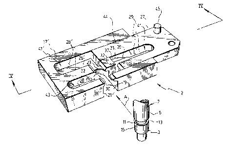
Referring to Figure 2, the apparatus according to a first aspect of the
invention is used for separating a cap 3 from a shank 5 of a tip 7 of a
welding
electrode. The cap 3 and the shank 5 form a peripheral hollow joint 11 that is
defiined by a recessed end surface '! 3 of the shank 5 and a back surface 15
of the
ca p 3.
Referring back to Figure 1, a robotic welder, the body of which is not
shown, has an arm 10 which preferably holds twa fingers 9 and 9' holding the
tips
land 7' of the welding electrodes that face each other in a closable clamping
arrangement. The tips 7, 7' of the welding electrodes are preferably identical
to
each other. The fingers 9 and 9' are pivotally mounted on a pivot point 72 of
the
arm 10 so that the robot welder can move them between open and closed
positions. !t will be understood of course that according to the present
invention
only one welding electrode may be used instead of the two that are shown.
Referring back to Figure 2, the apparatus includes a guide frame 17 having
a recessed portion 19 sized for receiving the tip 7 of the welding electrode.
The
recessed portion 19 extends in a direction perpendicular to the tip 7 of the
welding
electrode and has two facing side walls 21 and an end wall 23. The side walls
21
have guiding ribs 25 that are inserted in the peripheral hollow joint 11 for
guiding
the tip 7 of the welding electrode into the recessed portion 19, along the
direction
depicted by arrow A, until the tip 7 of the welding electrode is abutted
against the
end wall 23 in an engaged position.
The apparatus also includes a cap withdrawing tool 27 movably mounted
on the guide frame 17. The cap withdrawing tool 27 is movable along a
crosswise
direction, as depicted by arrow B, that is perpendicular with respect to both
the tip
CA 02421337 2003-03-07
7
7 and the recessed portion 19 when the tip 7 of the welding electrode is in
the
engaged position, as shown for example in Figures 5 and 7. The tool 27 has two
facing wall sections 29 each having a wedge 31 that is inserted in the
peripheral
hollow joint 11 when the tool 27 is moved toward the tip 7 of the electrode
that is
in the engaged position. When the tool 27 is moved toward the tip 7 of the
electrode, as shown for example in Figures 6 and 8, the wedge 31 is forced
against the back surface 15 of the cap 3 and thereby removes the cap 3 from
the
shank 5, as shown for example in Figures 3 and 9:
Referring to Figures 10 and 11, the apparatus also includes a driving
mechanism 33 coupled to the cap withdrawing tool 27 for moving the cap
withdrawing tool 27 toward and away from the tip 7 of the welding electrode
along
the crosswise direction between an open position, as shown for example in
Figure
10, where the tip 7 of the electrode is inserted into and removed from the
recessed portion 19 of the guide frame 17 and a closed position, as shown for
example in Figure 11, where the wedge 31 removes the cap 3 from the shank 5.
Of course, those skilled in the art will understand that many driving
mechanisms
may be used for moving the cap withdrawing tool 27 back and forth between in
its
open and closed positions. A hydraulic or pneumatic piston connected to the
cap
withdrawing tool may be used for example. However, as it will be further
described
below, the driving mechanism 33 may also serve another purpose of indexing a
rotatable cap supply drum 53 that is positioned adjacent to the guide frame 17
and
cap withdrawing tool 27.
Referring to Figure 8, it is preferable that each wedge 31 be provided with a
knife edge 35 that is forced into the back surface 15 of the cap 3 for
removing the
cap 3 from the shank 5 when the cap withdrawing tool 27 is moved toward the
tip
7 of the electrode that is in the engaged position. It is to be noted that if
the back
surface 15 of the cap 3 is very thin, as is the case for most caps used in the
industry, then a cap withdrawing tool that is not provided with a knife edge
may
not perform satisfactorily to remove the cap. Furthermore, because electrode
caps
are generally made of copper, which is a soft conducting metal, the problem
may
be worsened, because using a wedge 31 without a knife edge 35 might crush the
thin and soft back surface 15 of the electrode cap 3. This is one of the
reasons
CA 02421337 2003-03-07
why knife edges 35 are preferably provided for on the wedges 31. If a knife
edge
35 is provided on the wedge 31, it is preferable that it form an angle of
about 2
degrees with respect to the back surface 15 of the cap 3 when the tip 7 of the
electrode 9 is in the engaged position.
Referring to Figures 2 to 6, the wedge 31 preferably has a flat section 37
followed by an angled section 39, which forms an angle of about 17 degrees
with
respect to the flat section 37. With such a configuration, the wedge 31 is
progressively forced against the back surface 15 of the cap 3, without
damaging
the shoulder of the shank 5. Of course, other suitable angles and
configurations
may be selected to achieve the same results as it will be understood by those
skilled in the art.
Preferably, the guide frame 17 has two parallel grooved channels 43, 43'
extending along the crosswise direction and a grooved portion 44 that support
the
cap withdrawing tool 27. The grooved channels 43, 43' are perpendicular to and
intersect the recessed portion 19. Furthermore, the cap withdrawing tool 27
has a
complementary shape fitting into the grooved channels 43, 43' for movement
thereof along the crosswise direction. Each of the grooved channels 43, 43'
has a
bottom face 26, 26' that extends all the way to the grooved portion 44. The
facing
walls 28, 28' of the grooved channels 43, 43' guide the cap withdrawing tool
27
along the crosswise direction as it is moved across the guide frame 17 along
the
crosswise direction. One of the grooved channels 43 extends across and beyond
both side walls 21 of the recessed portion 19 at about a mid portion thereof.
The
other grooved channel 43' extends tangentially with respect to the end wall 23
of
the recessed portion 19. The grooved portion 44 is adjacent to and
communicates
with the parallel grooved channels 43, 43'. Both grooved channels 43, 43'
communicate with each other through a channel 30 extending above and parallel
to the recessed portion 19. The channel 30 is sized so as to allow the tip 7
of the
electrode to fit therein as it is abutted against the end wall 23. The channel
30
separates two middle portions 32 of the guide frame 1'7, which are further
defined
by the grooved channels 43, 43'.
The cap withdrawing tool 27 preferably has a U-shape that defines a
recessed section 41 also sized for engaging with the tip 7 of the electrode.
The
CA 02421337 2003-03-07
9
recessed section 41 of the U-shaped cap withdrawing tool 27 is the one that is
preferably provided with the facing walls sections 29 and wedges 31.
The driving mechanism 33 is preferably coupled to a proximity sensor 4
directed toward the recessed portion 19 of the guide frame 17 for detecting
that
the tip 7 of the welding electrode is in the engaged position and sending a
signal
to the driving mechanism 33 for moving the tool 27 toward the tip 7 of the
electrode. It is to be understood that the proximity sensor may be located in
a
position that is different from the one illustrated. Furthermore, other means
may
used to determine that the tip 7 of the electrode is in the engaged position=
such
as for example a position sensor provided on the robot welder that sends the
appropriate signals to the driving mechanism for moving the cap withdrawing
tool
27 in a suitable manner.
The following portion of the description is now concerned with another
aspect of the invention, namely the replacement of the cap 3 with a new cap 54
that is provided on a rotatabie cap supply drum 53.
Referring to Figures 1, 10 and 11, the guide frame 17 and the cap
withdrawing tool 27 both define a first cap withdrawing set 2 that is mounted
on a
first end of a support plate 40. A second end of the support plate 40 further
supports a second cap withdrawing set 2" which is substantially identical to
the
first cap withdrawing set 2. Both sets 2, 2' face in the same direction toward
the
robot welder holding the tips 7, 7'. The difference is that the second set 2'
is
positioned upside down with respect to the first set 2.. Both sets are
connected to
proximity sensors 4, 4'. As will be described further below, the driving
mechanism
33 is coupled to both cap withdrawing tools 27 of each set 2, 2'. The reason
the
second set 2' is in an upside down position is to avoid having to turn the arm
10 of
the robot welder upside down when replacing the caps 3, 3'. This feature saves
times and therefore improves tha efficiency of the apparatus.
The support plate 40 is preferably positioned horizontally and is fixed to a
vertical support plate 42. Furthermore, it is preferably to use a xyz
compliance
positioning system (not shown) connected to the support plate 40 for adjusting
and correcting the position of all the elements mounted on the support plate
40
with respect to the robotic welder.
CA 02421337 2003-03-07
Preferably, each of the cap withdrawing tools 27 has a pin 45 projecting
therefrom for cooperating with the driving mechanism 33. The driving mechanism
33 includes a push rod 46 connected to two drive plates 47, 47' by means of a
transverse bar 48. Each drive plate 47, 47' has an angled slot 49, 49'
slidably
5 receiving the pin 45 of a corresponding cap withdrawing tool 27 for moving
the
cap withdrawing tools toward and away from the tip 7 of the welding electrode
which is in the engaged position in one of the recessed portions 19 or
19°. One of
the drive plates 47 has a side slot 57 for indexing a rotatable cap supply
drum 53.
The push rod 46 is actuated by any suitable means such as a pneumatic motor
for
10 example that moves the rod 46 back and forth. Of course, those skilled in
the art
will understand that this movement must be coordinated with that of the robot
welder which is in turn precisely controlled by a program.
The cap supply drum 53 is mounted on the support plate 40 and can only
turn in one direction, which in this example is anti-clockwise, so that a new
cap 54
to be withdrawn is always present at a home position thereof. i he following
descriptive portion will explain the details of the indexing mechanism 60 of
the
support plate 53. To achieve this result a sprocket wheel 55 is provided with
teeth
directed in the opposite turning direction. The sprocket wheel is mounted on
spacers 58 mounted on the support frame 40. A spring loaded tab 57 engages
each of the teeth a time so that the sprocket wheel 55 is blocked from going
in an
opposite direction. An indexing disk 59 is mounted on the sprocket wheel 55 by
means or' two pins 61. The indexing disk 59 is made of an outer ring 63
provided
with inner cavities 65 disposed all around the ring 63. The distance between
the
cavities 65 determines the distance by which the cap supply drum 53 is
rotated.
The indexing disk 59 also has an inner ring 67 positioned within the outer
ring 63.
The inner ring 67 is provided with spring loaded locking members 69
cooperating
with the cavities 65 of the outer ring 63. The outer ring 59 is provided with
an
indexing tab 71 that is pushed back and forth by the side slot 51 of one of
the
drive plates 47. Onto the indexing disk 59 is mounted a spacer 73 that is
placed
under the disk 77. A screw 74 is used to secure the spacer 73 and the indexing
disk 59. Another screw 78 is used to secure the spacer 73, the disk 77 and the
cap 75 of the cap supply drum 53. The cap supply drum 53 includes a rotatable
CA 02421337 2003-03-07
11
disk 77 having cap holders 56 extending next to one another around the disk 77
in
alternating upside and downside positions. Each cap holder 56 holds a new cap
54 which is positioned in an opposite direction with respect to an adjacent
new
cap 54'. The cap holders 56 are resiliently biased by means of springs 79.
The following portion of the description will row describe a method of
separating and replacing first and second caps 3, 3' from first and second
shanks
5, 5' of first and second tips 7, 7' of welding electrodes. As mentioned above
the
tips 7, 7' face each other in a closable clamp arrangement and are held by
opposite fingers 9, 9' pivotally mounted on an arm 10 ~of a welding robot.
Similarly
as explained above the caps and the shanks form first and second peripheral
hollow joints 11, 11' that are defined by recessed end surFaces 13, 13' of the
shanks 5, 5' and back surfaces 15, 15' of the caps 3, 3'. The method according
to
a preferred embodiment of the present invention comprises the steps of:
a) inserting the first tip 7 of the first welding electrode, as depicted by
arrow
~i 5 A or' Figure 16, by means of the robot welder, in a nrst recessed portion
19 or' a
first guide frame 17, the first recessed portion extending in a direction
perpendicular to the first tip 7 and having two first facing side walls 21
provided
with first guiding ribs 25 and a first end wall 23;
b) guiding the first tip 7 of the first electrode by means of the first
guiding
ribs 25 of the first side walls 21 that are inserted in the first peripheral
hollow joint
11 until the first tip 7 of the welding electrode is abutted against the first
end wall
23 in a first engaged position;
c) detecting that the first tip 7 of the first welding electrode is in the
engaged position;
d) moving a first cap withdrawing tool 27 in a closed position, the first tool
27 being mounted on the first guide frame 17 along a first crosswise
direction, as
depicted by arrow B of Figure 3, that is perpendicular with respect to both
the first
tip 7 and the first recessed portion 19, the first tool 27 having two facing
wall
sections 29 each having a wedge 31 being inserted in the first peripheral
hollow
joint 11 and forced against the back surface 15 of the first cap 3, thereby
removing
the first cap 3 from the first shank 5;
e) moving the first cap withdrawing tool 27 in an open position, as shown
CA 02421337 2003-03-07
12
for example in Figure 10, along the crosswise direction and .simultaneously
actuating an indexing mechanism 60 that moves a first new cap 54 mounted on a
first holder 56 of a cap supply drum 53 in a home position, as depicted for
example by arrow D of Figure 16;
f) positioning the first and second tips 7, 7' by means of the robot welder in
the home position where the first tip 7 is irt alignment with the first new
cap 54, as
depicted for example by arrow C of Figure 16;
g) closing the first tip 7 against the second tip 7' to insert the first new
cap
54 into the first shank 5 of the first tip 7;
h) inserting the second tip 7' of the second welding electrode, as depicted
by arrow A' of Figure 16, by means of the robot welder, in a second recessed
portion 19' of a second guide frame 17', the second recessed portion 17'
extending in a direction perpendicular to the second tip T and having two
second
facing side walls 21' provided with second guiding ribs 25' and a second end
wall
23', the second guide frame 1T being upside down with respect to the frst
guide
frame 17;
i) guiding the second tip 7' of the electrode by means of the second guiding
ribs 25' of the second side walls 21' that are inserted in the second
peripheral
hollow joint 11' until the second tip 7' of the welding electrode is abutted
against
the second end wall 23' in a second engaged position;
j) detecting that the second tip 7' of the welding electrode is in the engaged
position;
k) moving a second cap withdrawing tool 27' in a closed position, the
second tool 27 being mounted on the second guide frame 1 T along a second
crosswise direction that is perpendicular with respect to both the second tip
7' and
the second recessed portion 19', the second tool 27' having two facing wall
sections 28' each having a wedge 31' being inserted in the second peripheral
hollow joint 11' and forced against the back surface '15' of the second cap
3',
thereby removing the second cap 3' from the second shank 5';
I) moving the second cap withdrawing tool 27' in an open position along the
crosswise direction and simultaneously actuating the indexing mechanism 60
that
moves a second new cap 54' mounted on a second holder 56' of the cap supply
CA 02421337 2003-03-07
13
drum 53 in the home position, as depicted for example by arrow D of Figure 16;
m) positioning the first and second tips 7, 7' by means of the robot welder in
the home position where the second tip T is in alignment with the second new
cap
54', as depicted for example by arrow C' of Figure 16; and
n) closing the second tip T against the first tip 7 to insert the second new
cap 54' into the second shank 5' of the second tip 7'.
The apparatus and method for separating a cap from a welding electrode
and replacing the cap with a new cap according to the present invention are
simpler and more efficient than those provided in prior art. Indeed, only a
single
actuator is needed to simultaneously perform both functions of removing a cap
from its electrode and automatically indexing of a cap supply drum. The
apparatus
and method are thus easily integrated in industrial plants, such as in
automobile
factories, which tend to be more and more completely automated.
Aithough preferred embodiments of the present invention have been
described in detail herein and illustrated in the accompanying drawings, it is
to be
understood that the invention is not limited to these precise embodiments and
that
various changes and modifications may be effected therein without departing
from
the scope or spirit of the present invention.