Note: Descriptions are shown in the official language in which they were submitted.
CA 02421481 2003-03-11
4
- 1 -
AUTOMOTIVE AIR CONDITIONING SYSTEM
BACKGROUND OF THE INVENTION
1. Field of the Invention
The present invention relates to an automotive
air conditioning system for heating the interior of the
passenger compartment of a vehicle, and more particularly
to an automotive air conditioning system with a hot gas
cycle for heating air passing through an air conditioning
duct with an interior heat exchanger (an evaporator)
provided inside the passenger compartment by causing hot,
high-pressure gas refrigerant discharged from a
refrigerant compressor to bypass an exterior heat
exchanger (a condenser) provided outside the passenger
compartment so as to be introduced directly to a pressure
reducing device and then to the interior heat exchanger
in that order.
2. Description of the Related Art
Generally used as an automotive air
conditioning system or, in particular, as an automotive
heating system, is a hot-water heating system for heating
the interior of the passenger compartment of a vehicle by
introducing engine cooling water to a hot-water heater
located in an air conditioning duct so as to heat air
passing through the air conditioning duct. with the hot-
water heating system of this type, however, there is
caused a drawback that a remarkable shortage of heating
capacity is experienced, just after the hot-water heating
system has been started, in the case where the heating
system is activated, by starting the engine, when the
temperatures of the outside air and cooling water are
low.
with a view to eliminating the drawback, there
has been proposed an automotive air conditioning system
with a hot gas cycle which functions as an auxiliary
heating system designed to assist the heating work of a
CA 02421481 2003-03-11
- 2 -
main heating system, for heating the vehicle interior by
making use of engine cooling water, by causing hot, high-
pressure gas refrigerant (hot gas) compressed and
discharged by a refrigerant compressor in a normal
refrigeration cycle to bypass an exterior heat exchanger
(a refrigerant condenser) so that the gas refrigerant is
passed through a pressure reducing device and is then
supplied to an interior heat exchanger (a refrigerant
evaporator) located within an air conditioning duct so as
to heat air passing through the air conditioning duct.
Note that the refrigerant compressor is belt driven by
the engine via an electromagnetic clutch.
When attempting to heat the vehicle interior
quickly, in the event that the temperature of the engine
cooling water is equal to or higher than a predetermined
temperature, as the heating capacity of the main heating
system is good enough to heat the vehicle interior, the
refrigerant compressor is controlled to be switched off
so as to stop the hot gas cycle, while in the event that
the temperature of the cooling water is lower than the
predetermined temperature, as the heating capacity of the
main heating system is not sufficient to do the required
work, the refrigerant compressor is controlled to be
switched on so as to activate the hot gas cycle.
Here, the hot gas cycle works differently from
a normal heat pump cycle in which the interior heat
exchanger provided inside the passenger compartment is
caused to work as a refrigerant condenser and the
exterior heat exchanger provided outside the passenger
compartment is caused to work as the refrigerant
evaporator and is designed such that heat resulting from
the compression work of the refrigerant compressor is
dissipated from the interior heat exchanger (the
refrigerant evaporator in the cooling mode), and
therefore, the hot gas cycle can operate at extremely low
outside air temperatures such as those in the vicinity of
-40°C.
CA 02421481 2003-03-11
- 3 -
In the related art, however, when the
temperature is extremely low and is, for example, -20°C
or lower, due to the property of the refrigerant called
HFC-134a, there occurs a case where a negative pressure
(a pressure lower than the atmospheric pressure, such as
an atmospheric pressure of Okg/cm2G at -26°C) is created
before the refrigerant compressor is activated. In
addition, due to the property of the hot gas cycle, as an
intake pressure taken into an intake portion of the
refrigerant compressor just after the compressor has been
activated tends to rise gradually after the intake
pressure has lowered once, it is confirmed that the
frequency at which the negative pressure is created at
the intake portion of the refrigerant compressor is very
high.
Incidentally, as to the fact that the negative
pressure is created at the intake portion, in engine-
driven type refrigerant compressors that are currently
used commonly, a shaft seal portion is found to be weak,
and when the intake pressure of the refrigerant
compressor lowers to or below a predetermined value (for
example, -0.5kg/cm2G), there is caused a possibility that
air enters the interior of the refrigerant compressor
from the shaft seal portion. As an ingress of air into
the interior of the refrigerant compressor like this
results in the generation of corrosion within the cycle
or an abnormal rise of the high pressure (condensing
pressure) at the time of cooling, such an ingress of air
must be prevented.
with a view to eliminating the above drawback,
in a related art disclosed in United States Patent No.
6,237,681, in the event that a physical amount related to
an intake pressure taken into a refrigerant compressor,
that is detected by an intake pressure detecting device,
becomes smaller than a predetermined value when a hot gas
cycle is activated in a condition where the outside air
temperature is extremely low, the refrigerant compressor
CA 02421481 2003-03-11
- 4 -
is automatically stopped so as to stop the operation of
an auxiliary heating system, whereby a reduction in
intake pressure of the refrigerant compressor, that
occurs just after the refrigerant compressor has been
activated, can be prevented, the generation of a negative
pressure at the intake portion of the refrigerant
compressor being thereby prevented.
Furthermore, under a low temperature
environment where the outside air temperature falls to or
below -10°C, as the temperature and pressure of the
refrigerant decrease to,thereby increase the specific
volume of the refrigerant, the weight flow rate of
refrigerant, that is taken into the refrigerant
compressor, becomes smaller and hence, the refrigerant
compressor does not work sufficiently, resulting in a
shortage of an auxiliary heating capacity.
with a view to eliminating the drawback, in a
related art disclosed in Japanese Unexamined Patent
Publication (Kokai) No. 11-42934, as shown in Fig. 8, a
refrigerant heating unit 9 is provided for heating a
refrigerant flowing through a refrigerant flow path 30
extending from an exit of a refrigerant evaporator 6 to
an intake opening of a refrigerant compressor 7. The
provision of the refrigerant heating unit 9 increases the
temperature and pressure of refrigerant that is taken
into the refrigerant compressor 7, and the specific
volume of the refrigerant is decreased, while the weight
flow rate of the refrigerant is increased, whereby the
refrigerant compressor is allowed to work sufficiently,
thereby making it possible to increase the auxiliary
heating capacity.
In the related art disclosed in the above
Japanese Unexamined Patent Publication, however, while
the auxiliary heating capacity is increased by heating a
low pressure side (from the exit of the refrigerant
evaporator to the intake opening of the refrigerant
compressor) of the hot gas cycle, the related art was not
CA 02421481 2003-03-11
- 5 -
effective against a drawback that internal components of
the refrigerant compressor wear or fail due to an ingress
of air into the interior of the refrigerant compressor
resulting from the generation of a negative pressure,
which is lower than the atmospheric pressure, occurring
in the interior of the compressor when the hot gas cycle
is activated in a condition where the outside air
temperature is extremely low, or insufficient lubrication
of the interior of the refrigerant compressor resulting
from no return of refrigerant and oil to the compressor
after it has been activated due to the low pressure and
density of the refrigerant.
However, the inventors of the present invention
recognized that the temperature of refrigerant within the
hot gas cycle (in particular, within the refrigerant
compressor) tends to continue to increase at all times
once the engine has been started. This tendency was
considered to be grounded on the facts that heat
generated from the engine is conducted to the refrigerant
compressor, as the refrigerant compressor is fixed to the
engine, and that heat building up inside the engine
compartment is conducted to the interior of the hot gas
cycle. The inventors then considered, based upon this
rationale, that, as the weight of refrigerant per volume
increases and the temperature within the hot gas cycle
increases with passage of certain time without estimating
an intake pressure, the generation of a large magnitude
of negative pressure in the refrigerant compressor can be
prevented and the return of refrigerant and oil from the
refrigerant condenser and so on can be improved.
SUMMARY OF THE TNVENTION
The present invention was made based upon the
aforesaid knowledge and considerations, and an object
thereof is to provide an automotive air conditioning
system which can prevent the ingress of air into the
interior of a refrigerant compressor, when a hot gas
cycle is activated, to thereby prevent the generation of
CA 02421481 2003-03-11
- 6 -
corrosion within the hot gas cycle due to the ingress of
air into the interior of the compression without
providing an intake pressure detecting unit and improving
a shaft seal portion of the refrigerant compressor, and
which can improve the return of refrigerant and oil from
a refrigerant condenser to the refrigerant compressor
when the hot gas cycle is activated.
According to one aspect of the present invention,
there is provided an automotive air conditioning system
comprising a main heating unit for heating air passing
through the interior of an air conditioning duct with
engine cooling water and a refrigeration cycle unit
having a first refrigerant circulating circuit for a
cooler mode and a second refrigerant circulating circuit
for a heater made which is auxiliary heating and designed
such that the operation of the automotive air
conditioning system is controlled by an air controlling
unit, wherein a refrigerant compressor is switched off
until a predetermined time T1 has elapsed after an engine
is activated in the event that the heating load is equal
to or larger than a predetermined value while the
automotive air conditioning system is operated in the
heater mode which is auxiliary heating. According to
this construction, as heat generated from the engine is
conducted to the refrigerant compressor and warms up the
interior of an engine compartment, the temperature of
refrigerant within the hot gas cycle, which is the second
refrigerant circulating circuit, is increased and the
weight of refrigerant per volume is increased, whereby
the generation of a large negative pressure within the
refrigerant compressor is prevented and the return of
refrigerant and oil to the refrigerant compressor can be
improved.
In the automotive air conditioning system of the
present invention, any of the outside air temperature,
the inside air temperature, the refrigerant evaporator
downstream air temperature and the cooling water
CA 02421481 2003-03-11
temperature is used as a numerical value representing the
heating load.
In the automotive air conditioning system of the
present invention, a heater is mounted along the path of
the second refrigerant circulating circuit, and the
heater is kept switched on after the engine has been
started when the automotive air conditioning system is
operated in the heater mode, while the refrigerant
compressor may be kept switched off only for a time T2
which is shorter than the predetermined time T1. Thus,
even in the event that a time during which the
refrigerant compressor is switched off is shorter, the
activation of the hot gas cycle can be started without
generating a large negative pressure within the
refrigerant compressor by heating the second refrigerant
circulating circuit also with the heater when the engine
is activated. Consequently, the time needed until the
passenger can feel warmth can be shortened.
In the automotive air conditioning system of the
present invention, the heater may be provide in an
accumulator. The refrigerant can be heated effectively
by the provision of the heater in the accumulator which
is a reservoir of refrigerant.
According to another aspect of the present
invention, there is provided an automotive air
conditioning system having an auxiliary heating function
for causing hot, high-pressure refrigerant discharged
from a refrigerant compressor at the time of heating to
bypass a refrigerant condenser so as to be introduced
directly to a refrigerant evaporator so that air is
heated with this refrigerant evaporator, wherein a
heating unit is provided in the refrigerant compressor
for heating the refrigerant compressor when the heating
load is equal to or larger than a predetermined value in
attempting to start the auxiliary heating function
working. According to the construction, the increase in
the temperature of refrigerant within a hot gas cycle
CA 02421481 2003-03-11
which performs the auxiliary heating function when the
outside air temperature is extremely low can be improved
and a time needed before the hot gas starts to operate
can be shortened, whereby a time needed before the
passenger can feel warmth can be shortened. In addition,
the pressure within the refrigerant compressor when the
hot gas operates can be increased, whereby an ingress of
air into the refrigerant compressor can be prevented.
In the automotive air conditioning system of the
present invention, the refrigerant compressor is coupled
to the engine via a clutch.
Tn the automotive air conditioning system of the
present invention, a refrigerant compressor having a
vapor-liquid separator therein is used as the refrigerant
compressor, whereby both the compressor and the vapor-
liquid separator may be heated by the heating unit.
According to the construction, in operating the hot gas
cycle when the outside air temperature is extremely low,
by warming up liquid refrigerant remaining in the vapor-
liquid separator, refrigerant is evaporated, whereby the
density and flow rate of refrigerant are increased, the
auxiliary heating capacity being thereby increased
remarkably.
In the automotive air conditioning system of the
present invention, an electric heater provided in the
interior or on the circumference of the refrigerant
compressor, or on the circumference of the vapor-liquid
separator may be adopted as the heating unit.
In the automotive air conditioning system of the
present invention, the refrigerant compressor is heated
with the heating unit, after the engine has been started
up, when the heating load is equal to or larger than the
predetermined value; and in the event that a hot gas
switch is not turned on even after a predetermined time
(T2) has elapsed, the heating unit is switched off.
According to this construction, unnecessary heating by
the heating unit can be prevented.
CA 02421481 2003-03-11
- 9 -
The present invention may be more fully understood
from the description of preferred embodiments of the
invention, as set forth below, together with the
accompanying drawings.
BRIEF DESCRIPTION OF THE DRAWINGS
In the drawings;
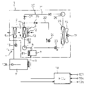
Fig. 1 is a diagram showing the overall construction
of an automotive air conditioning system according to a
first embodiment of the present invention,
Fig. 2 is a flow chart showing the operation of a
hot gas when the automotive air conditioning system
according to the first embodiment is operated in a heater
mode,
Fig. 3 is a graph showing a tendency for the
temperature of cooling water and the surface temperature
of a compressor to increase after an engine has been
started up,
Fig. 4 is a diagram showing the overall construction
of an automotive air conditioning system according to a
second embodiment of the present invention,
Fig. 5 is a flow chart showing the operation of a
hot gas when the automotive air conditioning system
according to the second embodiment is operated in a
heater mode,
Fig. 6 is a diagram showing the overall construction
of an automotive air conditioning system according to a
third embodiment of the present invention,
Fig. 7 is a sectional view of a refrigerant
compressor of an automotive air conditioning system
according to a fourth embodiment of the present
invention, and
Fig. 8 i,s a diagram showing the overall construction
of a conventional automotive air conditioning system.
DESCRIPTION OF THE PREFERRED EMBODIMENTS
Automotive air conditioning systems according to
embodiments of the present invention will be described
below with reference to the accompanying drawings. Note
CA 02421481 2003-03-11
- 10 -
that, while the present invention is described as being
applied to an automotive air conditioning system, the
present invention may be applied appropriately to a
general air conditioning system. Fig. 1 is a diagram
showing the overall construction of an automotive air
conditioning system according to a first,embodiment of
the present invention.
The automotive air conditioning system shown in Fig.
1 is constructed such that respective air conditioning
components in an air conditioning unit 1 for air
conditioning the interior of a passenger compartment of
an automobile, in which an engine E functioning as a main
heat source for heating is installed, are controlled by
an air conditioning control unit (ECU) 10.
The air conditioning unit 1 comprises an air
conditioning duct 2 constituting an air passage 1l for
introducing air conditioning air into the interior of a
passenger compartment. Provided at an upstream-most end
of the air conditioning duct 2 are an outside air intake
opening, an inside air intake opening and an inside
air/outside air switching door (none shown in the
figure), and a centrifugal blower 3 is provided
downstream thereof. In addition, provided at a
downstream-most end of the air conditioning duct 2 are
outlets such as defroster outlets, face outlets or foot
outlets and mode switching doors (not shown).
T L, n y- J- 1, .1- G t S. a- 1 7.. ~ y- /
n 11V L-wa l.'V~1 lleaLer J o1 a ilCJ L-wa Ler lleGitl.llg lAnl 1. t a
main heating unit) for re-heating air that has passed
through a refrigerant evaporator 6, which will be
described later, is provided upstream of the outlets.
This hot-water heater 5 is placed at an intermediate
position along the length of a cooling water circulating
circuit 14 in which a circulating flow of cooling water
is generated by a water pump (not shown) driven by the
engine E. Then, when a hot-water valve 15 placed at a
position along the length of the cooling water
circulating cirevit 14 is opened, cooling water that
CA 02421481 2003-03-11
- 11 -
absorbs therein heat discharged from the engine E is
circulated in the hot-water heater 5, and the hot-water
heater 5 re-heats air using this cooling water as a heat
source for heating. Here, the hot-water heating unit
(the main heating unit) 4 is constituted by the engine E,
the hot-water heater 5, the cooling water circulating
circuit 14 and the hot-water valve 15.
A refrigerant evaporator 6 constituting a
constituent component of a refrigeration cycle device 20
installed in the automobile is disposed between the
centrifugal blower 3 and the hot-water heater 5 in such a
manner as to totally close the air passage 11 within the
air conditioning duct 2. This refrigeration cycle device
comprises a first refrigerant circulating circuit (a
15 refrigeration cycle) 21, a second refrigerant circulating
circuit (a hot gas cycle) 22, and first and second
electromagnetic valves 23, 24 for switching circuits
between these first and second circuits 21, 22.
The first refrigerant circulating circuit 21 is a
20 refrigerant circuit for circulating hot, high-pressure
gas refrigerant discharged from a refrigerant compressor
7 through the first electromagnetic valve 23, a
refrigerant condenser 25, a receiver (a vapor-liquid
separator) 26, a first pressure reducing device 27, the
refrigerant evaporator 6, and an accumulator (a vapor-
liquid separator) 28 back to the refrigerant compressor 7
in that order. In addition, the second refrigerant
circulating circuit 22 is a refrigerant circuit for
circulating hot, high-pressure gas refrigerant (hot gas)
discharged from the refrigerant compressor 7 through the
second electromagnetic valve 24, a second pressure
reducing device 29, the refrigerant evaporator 6, and the
accumulator 28 back to the refrigerant compressor 7 in
that order. Note that the first pressure reducing device
27 and the second pressure reducing device 29 may be
incorporated into a single pressure reducing device so as
to be commonly used for the refrigeration cycle and the
CA 02421481 2003-03-11
- 12 -
hot gas cycle.
In the refrigeration cycle device 20, when the first
electromagnetic valve 23 opens and the second
electromagnetic valve 24 closes, refrigerant circulates
through the first refrigerant circulating circuit 21,
whereas when the first electromagnetic valve 23 closes
and the second electromagnetic valve 24 opens,
refrigerant circulates through the second refrigerant
circulating circuit 22. Note that a circulating circuit
switching device is constituted by the first and second
electromagnetic valves 23, 24. In addition, reference
numeral 16 denotes a cooling fan driven to rotate by a
driving motor 17 for forcibly blowing outside air against
the refrigerant condenser 25.
The refrigerant evaporator 6 is such as to
correspond to an interior heat exchanger provided inside
the passenger compartment and works as a cooling heat
exchanger for evaporating low-temperature, vapor-liquid
two-phase refrigerant that flows thereinto from the first
pressure reducing device 27 when refrigerant flows
through the first refrigerant circulating circuit 21 to
thereby cool air passing therethrough. In addition, the
refrigerant evaporator 6 works as a heating heat
exchanger (an auxiliary heating unit) for allowing high-
temperature or hot gas refrigerant that flows thereinto
from the second pressure reducing device 29 when
refrigerant flows through the second refrigerant
circulating circuit 22 to flow therethrough to thereby
heat air passing therethrough.
The refrigerant compressor 7 is an engine-driven
compressor for compressing refrigerant taken thereinto
from an intake opening thereof and discharging hot, high-
pressure gas refrigerant from a discharge opening
thereof. In this case, either a variable-displacement
type compressor or a fixed-displacement compressor may be
used. Connected to a shaft of this refricrerant
compressor 7 is an electromagnetic clutch 8 for effecting
CA 02421481 2003-03-11
- 13 -
and cutting off the transmission of the rotating power of
the engine E to the refrigerant compressor 7. In
addition, a V-belt is wound around a pulley 81 of the
electromagnetic clutch 8. The V-belt is also wound
around a crank pulley of the engine E to thereby enable
the transmission of the rotating power of the engine E to
the refrigerant compressor 7.
When the electromagnetic clutch 8 is in an energized
(ON) condition, the rotating power of the engine E is
transmitted to the refrigerant compressor 7 via the V-
belt and the electromagnetic clutch 8, whereby the
refrigeration cycle is activated and the air cooling
operation or air heating operation is implemented by the
refrigerant evaporator 6. In addition, when the
electromagnetic clutch 8 is in a de-energized (OFF)
condition, the power of the engine E is not transmitted
to the refrigerant compressor 7, and the air cooling
operation or the air heating operation by the refrigerant
evaporator 6 is stopped.
Respective switch signals from respective switches
on a control panel (not shown) provided at the front of
the passenger compartment are inputted into the ECU (the
air conditioning electric control unit) 10 for
controlling respective air conditioning components in the
air conditioning unit 1. Placed on the control panel are
a hot gas switch, a mode changeover switch for changing
over air conditioning modes between a cooler mode
(cooling operation) and a heater mode (heating
operation), a temperature setting switch for setting the
temperature inside the passenger compartment to a desired
temperature, an air conditioner switch for commanding the
refrigeration cycle device 20 to be activated or stopped
and a blower switch for commanding the centrifugal blower
3 to be switched on or off.
Additionally, a known microprocessor comprising a
CPU, a ROM, and a RAM is provided in the interior of the
ECU 10, and signals from respective sensors are
CA 02421481 2003-03-11
~ 14 -
configured to be inputted into the microprocessor after
the signals are A/D converted by an input circuit, not
shown. Furthermore, when an ignition switch (IG), which
governs the start and stop of the engine E of the
automobile, is closed (ON), the ECU 10 is configured to
start a control process with a direct-current power
supply being supplied thereto from a battery (not shown)
which is an onboard power supply installed in the
automobile.
Signals from an inside air temperature sensor 104
for detecting the temperature of air inside the passenger
compartment (inside air temperature), an outside air
temperature sensor 105 for detecting the temperature of
air outside the passenger compartment (outside air
temperature), a post-evaporator temperature sensor 107
for detecting the temperature of air that has just passed
through the refrigerant evaporator 6 (evaporator
downstream air temperature) and a cooling water
temperature sensor 108 for detecting the temperature of
cooling water that flows into the hot-water heater 5 are
inputted into the air conditioning control ECU 10,
respectively. Note that the aforesaid respective
switches and sensors are intended to detect air
conditioning environmental factors needed to condition
air inside the passenger compartment of the automobile,
and thermistors are used in the inside air temperature
sensor, outside air temperature sensor, post-evaporator
temperature sensor. and the cooling water temperature
sensor. In addition, a measuring device is provided in
the ECU 10 for computing the time that has elapsed since
the engine started.
Next, the hot gas operation of the automotive air
conditioning system constructed as described above
according to the first embodiment which constitutes a
feature of the present invention will be described based
on a flow chart shown in Fig. 2.
In step S1, the ignition switch (IG) is switched on,
CA 02421481 2003-03-11
- 15 -
and a direct-current power supply is supplied to the ECU
10. Then, in step S2, signals are read in from the
respective switches on the air conditioner control panel.
In step S3, signals are read in from the respective
sensors. To be specific, outside air temperature, inside
air temperature, evaporator .downstream air temperature
and cooling water temperature are read in.
Next, whether or not the air conditioning mode is in
the heater (heating) mode is determined (step S4).
Namely, whether or not the air conditioning mode is set
to the heater mode using the mode changeover switch is
determined. If the result of the determination is NO,
then the routine exits as shown in Fig. 2.
If the result of the determination in step S4 is
YES, or in the event that the air conditioning mode is in
the heater mode, whether or not the hot gas switch is
closed (ON) is determined (step S5). If the result of
the determination is N0, then the routine exits as shown
in Fig. 2 after the energization to the electromagnetic
clutch 8 is stopped so as to stop the refrigerant
compressor 7 automatically.
In addition, if the result of the determination in
step S5 is YES, or in the event that the hot gas switch
is switched on, then, the process advances to step S6,
and whether or not the heating load is equal to or larger
than a predetermined value is determined. For example,
whether or not, as the heating load, the outside
temperature is lower than the predetermined value (-30°C)
is determined. Note that in addition to outside air
temperature, inside air temperature, evaporator
downstream air temperature or cooling water temperature
may be adopted as the heating load. In addition, the
predetermined value can be set appropriately..
If the result of the determination in step S6 is
YES, namely, in the event that the outside temperature is
equal to or higher than -30°C, the electromagnetic switch
8 is switched on (step S7), and then, the refrigerant
CA 02421481 2003-03-11
- 16 -
compressor 7 being activated, the first electromagnetic
valve 23 being closed, and the second electromagnetic
valve 24 being opened, the hot gas operation is started
in the second refrigerant circulating circuit (the hot
gas cycle) 22 as designed.
If the result of the determination in step S6 is N0,
or in the event that the outside temperature is lower
than -30°C, the time that has elapsed since the engine
was started is computed, which is a feature of the
present invention, and in step S8, whether or not a time
T1, that has elapsed since the engine was started, is
equal to longer than 60 seconds is determined. Then, the
process advances to step S7 after 60 seconds has elapsed
since the engine was started, where the electromagnetic
clutch 8 being switched on, the refrigerant compressor 7
being activated, the first electromagnetic valve 23 being
closed, and the second electromagnetic valve 24 being
opened, the hot gas cycle operation is started in the
second refrigerant circulating circuit.
Thus, according the first embodiment of the present
invention, in the event that the heating load is equal to
or larger than the predetermined value, the hot gas cycle
operation is designed to be activated after a
predetermined time T1, for example, 60 seconds, has
elapsed since the engine was started, whereby heat from
the engine is conducted directly to the refrigerant
compressor and the interior of the engine compartment is
warmed up, and the heat is conducted to the interior of
the hot gas cycle to thereby increase the temperature
inside the cycle. Thus, even if the intake pressure of
the refrigerant compressor is not estimated, which is
required for the related art automotive air conditioning
system, the temperature within the hot gas cycle
increases with passage of a certain time and the
refrigerant weight per volume increases, whereby the
generation of a large negative pressure in the
refrigerant compressor can be prevented, and the return
CA 02421481 2003-03-11
- 17 -
of refrigerant and oil can be improved.
Fig. 3 is a graph showing how the temperature of
engine cooling water and the surface temperature of the
compressor rose after the engine was started up. The
axis of abscissas represents time (minutes) and the axis
of ordinates represents temperature (°C). In the graph,
a curve Gl represents the temperature of engine cooling
water; a curve G2 represents the surface temperature of
the compressor resulting when a variable-displacement
compressor was used as the compressor and the hot gas
operation was activated after 1 minute had elapsed since
the engine was started, a curve G3 represents the surface
temperature of the compressor resulting when a variable-
displacement compressor was used as the compressor and
there was activated no hot gas operation, a curve G4
represents the surface temperature of the compressor
resulting when a fixed-displacement compressor was used
as the compressor and the hot gas operation was activated
after 5 minutes had elapsed since the engine was started,
and G5 represents the surface temperature of the
compressor resulting when a fixed-displacement compressor
was used as the compressor and no hot gas operation was
activated.
The reason why the slopes of the rising curves of
the surface temperatures of the variable-displacement
compressors are steeper than those of the rising curves
of the surface temperatures of the fixed-displacement
compressors is because with the variable-displacement
compressors, the shaft rotated idly at the same time as
the engine was started, whereby heat was generated in the
compressor and the temperature inside the compressor was
increased largely. Thus, in Fig. 2, with the variable-
displacement compressor being used, switching the
electromagnetic clutch on and off means that the capacity
is controlled so as to become larger than 0~ and that the
capacity is controlled so as to become 0~, respectively.
Fig. 4 is a diagram showing the overall construction
CA 02421481 2003-03-11
- 18 -
of an automotive air conditioning system according to a
second embodiment of the present invention. In this
second embodiment, a heater 40 is mounted along a path
within a hot gas cycle which is a second refrigerant
circulating circuit 22, for example, on the circumference
or in the interior of an accumulator 28. Then, the
accumulator 28 is designed to be heated for a
predetermined time with a command from an ECU 10. The
remaining construction of the automotive air conditioning
system of the second embodiment remains the same as the
automotive air conditioning system according to the first
embodiment. Electric heaters such as a PTC heater, a
nichrome wire heater and a glow plug heater are preferred
to be used as the heater 40.
Next, the hot gas operation of the automotive air
conditioning system according to the second embodiment of
the present invention will be described based upon a flow
chart shown in Fig. 5.
In step T1, when an ignition switch (IG) is switched
on, a direct-current power supply is supplied to the ECU
10. Then, signals from respective switches on an air
conditioner control panel are read (step T2). In
addition, signals from respective sensors are also read
(step T3). To be specific, an outside air temperature,
an inside air temperature, an evaporator downstream air
temperature and a cooling water temperature are read.
Next, in step T4, whether or not the heating load is
equal to or larger than a predetermined value is
determined. For example, as the heating load, whether or
not the outside air temperature is lower than the
predetermined value (-30°C) is determined. Selecting the
heating load and setting the predetermined value therefor
are identical with those of the first embodiment.
If the result of the determination in step T4 is
YES, or in the event that the outside air temperature is
equal to or higher than -30°C, the process advances to
step T5, and whether or not the air conditioning mode is
CA 02421481 2003-03-11
- 19 -
in the heater mode is determined. If the result of the
determination is N0, then the routine exits as shown in
Fig. 5, whereas if the result of the determination is
YES, then the process advances to step T6, and whether or
not the hot gas switch is switched on is determined. If
the result, of the determination is N0, then the process
advances to step T7, where an electromagnetic clutch 8 is
switched off to thereby stop the refrigerant compressor
7. If the result of the determination is YES, then the
electromagnetic clutch 8 is switched on to thereby
activate the refrigerant compressor 7, whereby the hot
gas cycle operation is started. Part of the routine that
has been described heretofore is identical to that of the
first embodiment.
The routine according to the second embodiment is
characterized by part thereof that will be described
below. Namely, in step T4, if the result of the
determination is NO and in the event that 'the heating
load is equal to or larger than the predetermined value,
for example, in the event that the outside air
temperature is lower than -30°C, then, the process
advances to step T9, and the heater 40 of the accumulator
28 is switched on. Following this, in step T10, whether
or not the air conditioning mode is in the heater mode is
determined. If the result of the determination in step
T10 is YES, then, the process advances to step T11, where
whether or not the hot gas switch is switched on is
determined. When the heater is switched on in step T9,
then, the process advances to step T13, where the heating.
time of the heater 40 is computed, and in step T14, if
the heating time exceeds 600 seconds, then, the process
advances to T15, where the heater 40 is switched off.
If the result of the determination in step T11 is
N0, then advance to step T15, where the heater 40 is
switched off. In contrast, if the result of the
determination in the step T11 is YES, or in the event
that the hot gas switch is switched on, then, the process
CA 02421481 2003-03-11
- 20 -
advances to step T12, where whether or not the time that
has elapsed after the engine was started is equal to or
longer than a predetermined time T2, for example, 40
seconds, is determined, and if the time that has elapsed
is determined to be equal to or longer than 40 seconds,
then the electromagnetic clutch 8 is switched on, whereby
the refrigerant compressor 7 starts to operate the hot
gas cycle.
Thus, according to the second embodiment, in the
event that the outside air temperature, which is the
heating load, is lower than the predetermined value (for
example, -30°C) after the engine has been started, the
heater 40 is switched on: In the event that the hot gas
switch is not switched on a predetermined time T1 (for
example, 600 seconds) after the heater 40 has been
switched on, then the heater 40 is switched off. In
contrast, in the event that the hot gas switch is
switched on, then the heater 40 is kept switched on as it
is (until 600 seconds has elapsed).
Thus, according to the second embodiment, the heater
40 has been switched on before the hot gas cycle
operates, and due to this, when activated in a condition
where the outside air temperature is extremely low, the
increase in the temperature of refrigerant within the hot
gas cycle is improved, and the time needed before the hot
gas cycle operates becomes shorter than that of the first
embodiment, whereby the time needed before the passenger
feels warmness becomes shorter accordingly.
Fig. 6 is a diagram showing the overall construction
of an automotive air conditioning system according to a
third embodiment o the present invention. Basic
constituent parts of the automotive air conditioning
system of the third embodiment are identical with those
of the automotive air conditioning systems according to
the first and second embodiments shown in Figs. l and 4,
respectively.
The automotive air conditioning system according to
CA 02421481 2003-03-11
- 21 -
the third embodiment is constructed such that respective
air conditioning devices (actuators) in an air
conditioning unit 1 for air conditioning the interior of
the passenger compartment of an automobile an engine E
installed therein, which is a main heat source for
heating, are controlled by an air conditioning electric
control unit (ECU) 10.
The air conditioning unit 1 comprises an air
conditioning duct 2 for introducing air conditioning air
into the passenger compartment, and an outside air intake
opening, an inside air intake opening and an inside
air/outside air switching door (none shown in the figure)
are provided at an upstream-most end of the air
conditTOning duct 2, and a centrifugal blower 3 (refer to
Fig. 1) is provided downstream of the openings and the
door. In addition, outlets such as defroster outlets,
face outlets or foot outlets and mode switching doors
(not shown) are provided at a downstream-most end of the
air conditioning duct 2.
Next, a hot-water heater 5 for a hot-water heating
unit 4 which is a main heating unit for re-heating air
that has passed through a refrigerant evaporator 6, which
will be described later, is provided downstream of the
outlets. This hot-water heater 5 is placed at an
intermediate position along the length of a cooling water
circulating circuit 14 in which a circulating flow of
cooling water is generated by a water pump (not shown)
that is driven by the engine E. Cooling water that has
absorbed therein heat discharged from the engine E is
circulated in the interior of the hot-water heater 5, and
the hot-water heater 5 uses this cooling water as a heat
source for heating and re-heat air.
The evaporator 5 constituting one of constituent
components of a refrigeration cycle device 20 installed
in the automobile is disposed upstream of the hot-water
heater 5 in the air conditioning duct 2 in such a manner
as to close totally an air passage within the air
CA 02421481 2003-03-11
22 -
conditioning duct 2. The refrigeration cycle device 20
comprises a first refrigerant circulating (refrigeration
cycle) circuit 21 having a cooling function, a second
refrigerant circulating (hot gas heater) circuit 22
having an auxiliary heating function, and first and
second electromagnetic valves 23, 24 for,switching
circuits between.the refrigeration cycle circuit 21 and
the hot gas heater circuit 22.
The first refrigerant circulating (refrigeration
cycle) circuit 21 is such as to correspond to a cooling
and dehumidifying unit and circulates hot, high-pressure
gas refrigerant discharged from the refrigerant
compressor 7 through the first electromagnetic valve 23,
a refrigerant condenser 25, a receiver (vapor-liquid
separator) 26, an expansion valve (first pressure
reducing device) 27, the refrigerant evaporator 6, and an
accumulator (vapor-liquid separator) 28 back to the
refrigerant compressor 7, in that order. Namely, the
refrigeration cycle circuit 21 is a refrigeration circuit
in which the refrigerant evaporator 6 performs a air
cooling operation by supplying low-temperature, low-
pressure liquid refrigerant to the refrigerant evaporator
6 by allowing refrigerant to circulate through the
refrigeration cycle circuit 21 when the first
electromagnetic valve 23 opens and the second
electromagnetic valve closes.
The hot gas heater circuit 22, which corresponds to
the auxiliary heating unit according to the present
invention, circulates hot, high-pressure gas refrigerant
(hot gas) discharged from the refrigerant compressor 7
through the second electromagnetic valve 24, a pressure
reducing device (second pressure reducing device) 29, the
refrigerant evaporator 6, and the accumulator (vapor-
liquid separator) 28 back to the refrigerant compressor 7
in that order. Namely, the hot gas heater circuit 22 is
a refrigeration circuit in which the refrigerant
evaporator 6 performs an air heating operation by
CA 02421481 2003-03-11
- 23 -
allowing refrigerant to circulate through the hot gas
heater circuit 22 when the first electromagnetic valve 23
closes and the second electromagnetic valve 24 opens.
The refrigerant evaporator 6 functions as a cooling
heat exchanger for cooling air passing therethrough by
evaporating low-temperature vapor-liquid two-phase
refrigerant flowing thereinto from the expansion valve 27
when refrigerant flows through the refrigeration cycle
circuit 21 and functions as a heating heat exchanger for
heating air passing therethrough by evaporating high-
temperature vapor-liquid two-phase refrigerant flowing
thereinto fram the pressure reducing device 29 when
refrigerant flows through the hot gas heater circuit 22.
Here, the expansion valve 27 is intended not only to
insulate and expand refrigerant but also to regulate the
circulating amount of refrigerant in accordance with the
degree at which refrigerant that has exited from the
refrigerant evaporator 6 is super-heated and a
temperature sensing tube 27a for detecting the degree at
which refrigerant is super-heated is connected to the
expansion valve 27.
An electromagnetic valve 8 is coupled to the
refrigerant compressor 7 for effecting and cutting off
the transmission of the rotational power of the engine E
to the refrigerant compressor 7. when the
electromagnetic valve 8 is engergized (ON), the
rotational power of the engine E is transmitted to the
refrigerant compressor 7, and the refrigerant compressor
7 compresses and discharges refrigerant taken thereinto,
whereby the air cooling operation or air heating
operation is implemented by the refrigerant evaporator 6.
A heating unit comprising, for example, an electric
heater 9, which is a feature of the present invention, is
provided in the interior or on the circumference of the
refrigerant compressor 7. A PTC heater, a nichrome wire
heater or a glow plug heater is used as the electric
heater 9 and is electrically connected to a battery
CA 02421481 2003-03-11
- 24 -
installed in the automobile via a fuse 32 and a relay
circuit 33. An alternator 34 adapted to be driven by the
engine E to charge the battery 31 is electrically
connected to the battery 31. In addition, the relay
circuit 33 comprises a relay coil 33a which is switched
on and off by the ECU 10 and a relay switch 33b which is
closed when the relay coil 33a is switched on.
Furthermore, in the present invention, an electric
heater 9b is provided in such a manner as to be brought
into contact with an outer circumference of a suction
pipe 30 connecting the refrigerant evaporator 6 with the
accumulator (vapor-liquid separator) 28. This electric
heater 9b is also electrically connected to the battery
31. Consequently, both the electric heater 9a and the
electric heater 9b are electrically connected to the
battery 31 in a parallel fashion.
Signals are inputted into the ECU 10 for controlling
the respective air conditioning devices in the air
conditioning unit 1 from respective switches on an air
conditioner control panel provided on a front side of the
passenger compartment of the vehicle. Furthermore,
signals are also inputted into the ECU 10 from an inside
air temperature sensor 104 for detecting the temperature
of air inside the passenger compartment (inside air
temperature), an outside air temperature sensor 105 for
detecting the temperature of air autside the passenger
compartment (outside air temperature), a post-evaporator
temperature sensor 107 for detecting the temperature of
air that has just passed through the refrigerant
evaporator and a cooling water temperature sensor 108 for
detecting the temperature of cooling water flowing into
the hot-water heater 5. These respective switches and
sensors are intended to detect air conditioning
environmental factors needed to air condition the
interior of the passenger compartment of the automobile.
In addition, a known microcomputer comprising a CPU,
a ROM and a RAM is provided in the interior of the ECU
CA 02421481 2003-03-11
25 -
10, and signals from the respective sensors are designed
to be inputted into the microcomputer after they have
been A/D converted by an input circuit, not shown. Note
that the ECU 10 is configured to start the control
process when a direct-current power supply is supplied
thereto from a battery (not shown), which is a power
supply installed in the automobile, when the ignition
switch (IG) which governs the start and stop of the
engine E of the automobile is closed.
The automotive air conditioning system of the
present invention, that is constructed as has been
described heretofore, operates as will be described
below. when the hot gas operation for heating the
interior of the passenger compartment starts, the first
electromagnetic valve 23 is closed and the second
electromagnetic valve 24 is opened. In the event that
the heating load becomes equal to or larger than a
predetermined value after the engine has been started,
the electric heaters 9a, 9b are switched on so as to heat
the refrigerant compressor 7 and the suction pipe 30. As
this occurs, any one of an outside air temperature
detected by the outside air temperature sensor 105, the
inside air temperature detected by the inside air
temperature sensor 104, the air temperature downstream of
the refrigerant evaporator detected by the post-
evaporator air temperature sensor 107 and the cooling
water temperature detected by the cooling water
temperature sensor 108 is selected as a value
representing the heating load. For example, in the event
that the outside air temperature is lower than -30°C,
which is the predetermined value, the electric heaters
9a, 9b are switched on.
In the event that the hot gas switch is not switched
on even after a predetermined time (T2) has elapsed since
the electric heaters 9a, 9b were switched on after the
engine E was started, namely, in the event that the
electromagnetic clutch is switched on to thereby drive
CA 02421481 2003-03-11
- 26 -
the refrigerant compressor 7 but the hot gas operation is
not initiated, the electric heaters 9a, 9b are switched
off.
In contrast, in the event that the hot gas switch is
switched on and the hot gas operation is initiated, the
electric heaters 9a, 9b are kept switched on as they are
so as to continue to heat the refrigerant compressor 7
and the suction pipe 30 until a predetermined time (T1)
has elapsed since the engine E was started.
The aforesaid predetermined times (T1, T2) can be
set at random according to the heating load.
In addition, the electric heater 9 for heating the
suction pipe 30 is not necessarily provided.
Thus, according to the embodiment of the present
invention, as the heating device is provided on the
refrigerant compressor 7 so that the refrigerant
compressor 7 is heated with the heating device prior to
the operation of the hot gas, when activated in a
condition where the outside air temperature is extremely
low, the increase in the temperature of refrigerant
within the hot gas cycle is improved, and the time needed
before the hot gas cycle operates becomes shorter than
that of the first embodiment, whereby the time needed
before the passenger feels warmth becomes accordingly
shorter. In addition, the pressure in the interior of
the compressor is increased and the ingress of air into
the interior of the compressor can be prevented.
Furthermore, as the heating devices are switched on
during the operation of the hot gas, the heating
performance improving effect which is equal to the
quantity of heat generated by the heating devices can be
obtained.
In addition, even when the automotive air
conditioning system is initiated to implement the cooling
operation in summer, fluid is accumulated within the
interior of the compressor, and a fluid compression may
be caused, leading to a failure of the compressor. Even
CA 02421481 2003-03-11
27
when this occurs, however, by heating the compressor,
fluid remaining within the compressor can be forced out
of the compressor by evaporating the fluid.
Fig. 7 is a sectional view showing an automotive air
conditioning system according to a fourth embodiment of
the present invention. In this embodiment, a refrigerant
compressor 7 integrally having therein a vapor-liquid
separator 71 is used as the refrigerant compressor 7. A
heating device for the refrigerant compressor 7 is
provided as being inserted in the interior of the
refrigerant compressor 7 or being wound around the
circumference of the compressor or the vapor-liquid.
separator. In Fig. 7, an electric heater 9c is provided
as being wound around the circumference of the vapor-
liquid separator ?1 integrally provided on the
compressor. The remaining constructions thereof remain
the same as those of the aforesaid embodiments.
Note that in Fig. 7; while a wobble or swash plate
compressor is shown as being used as the compressor, the
present invention is not limited to compressors of that
type, and therefore, the present invention can be applied
to compressors of any type.
In this embodiment, in addition to the effectiveness
obtained by heating the refrigerant compressor 7 as has
been described in the previous embodiment, liquid
refrigerant accumulated in the interior of the vapor-
iiquid separator %1 integrally provided on the compressor
can be evaporated by heating the vapor-liquid separator
71 with the heating device, so that the density of
refrigerant increases and the flow rate of refrigerant
increases, whereby the capacity of the hot gas cycle can
remarkably be increased.
while the invention has been described by reference
to the specific embodiments chosen for purposes of
illustration, it should be apparent that numerous
modifications could be made thereto by those skilled in
the art without departing from the basic concept and
<IMG>