Language selection

Search

Patent 2421616 Summary

Third-party information liability

Some of the information on this Web page has been provided by external sources. The Government of Canada is not responsible for the accuracy, reliability or currency of the information supplied by external sources. Users wishing to rely upon this information should consult directly with the source of the information. Content provided by external sources is not subject to official languages, privacy and accessibility requirements.

Claims and Abstract availability

Any discrepancies in the text and image of the Claims and Abstract are due to differing posting times. Text of the Claims and Abstract are posted:

  • At the time the application is open to public inspection;
  • At the time of issue of the patent (grant).
(12) Patent Application: (11) CA 2421616
(54) English Title: COLUMN-TYPE MACHINE TOOL
(54) French Title: MACHINE-OUTIL A COLONNE
Status: Deemed Abandoned and Beyond the Period of Reinstatement - Pending Response to Notice of Disregarded Communication
Bibliographic Data
(51) International Patent Classification (IPC):
  • B23Q 01/01 (2006.01)
  • B23Q 11/00 (2006.01)
  • B23Q 11/08 (2006.01)
(72) Inventors :
  • STUDEMANN, BERND (Germany)
  • JODL, WERNER (Germany)
(73) Owners :
  • DORRIES SCHARMANN TECHNOLOGIES GMBH
(71) Applicants :
  • DORRIES SCHARMANN TECHNOLOGIES GMBH (Germany)
(74) Agent: NORTON ROSE FULBRIGHT CANADA LLP/S.E.N.C.R.L., S.R.L.
(74) Associate agent:
(45) Issued:
(86) PCT Filing Date: 2001-10-05
(87) Open to Public Inspection: 2003-02-26
Availability of licence: N/A
Dedicated to the Public: N/A
(25) Language of filing: English

Patent Cooperation Treaty (PCT): Yes
(86) PCT Filing Number: PCT/EP2001/011501
(87) International Publication Number: EP2001011501
(85) National Entry: 2003-02-26

(30) Application Priority Data:
Application No. Country/Territory Date
100 50 141.9 (Germany) 2000-10-11

Abstracts

English Abstract


The invention relates to a machine-tool, comprising a machine-bed and
guideways (5, 6) for a column (2) which is displaceable on the machine-bed.
One guideway (6) is situated beneath the column, another guideway (5) being
situated laterally adjacent to the column, at approximately half the height of
said column. This invention also comprises a travel drive (7) which engages
with the column at the height of said lateral guideway (5).


French Abstract

L'invention concerne une machine-outil comportant un socle (1) ainsi que des glissières (5, 6) pour une colonne (2) pouvant se déplacer sur ledit socle. Une glissière (6) est placée sous la colonne tandis que l'autre glissière (5) est disposée latéralement à côté de la colonne, à mi-hauteur de cette dernière. Cette machine-outil présente en outre un organe de commande de déplacement (7) qui vient en contact avec la colonne au niveau de la glissière latérale (5).

Claims

Note: Claims are shown in the official language in which they were submitted.

-6-
claims
1. A column-type machine tool, in particular a milling
center, having
- a traversable column (2) and a tool carrier (3) arranged
thereon,
- a machine bed (1),
- guideways (5, 6) for the column (2) traversable on the
machine bed (1), of which guideways (5, 6)
- one guideway (6) is arranged below the column (2) on the
machine bed (1),
- a further guideway (5) is arranged laterally next to the
column (2), approximately centrally at half the height
of the column (2) and approximately at the level of the
center of gravity of the column, and having
- a traverse drive (7) which acts on the column (2) at the
level of the lateral guideway (5) without a substantial
tilting moment acting on the column (2).

-6-
claims
1. A column-type machine tool, in particular a milling
center, having
- a traversable column (2) and a tool carrier (3) arranged
thereon,
- a machine bed (1),
- guideways (5, 6) for the column (2) traversable on the
machine bed (1), of which guideways (5, 6)
- one guideway (6) is arranged below the column (2) on the
machine bed (1),
- a further guideway (5) is arranged laterally next to the
column (2), approximately centrally at half the height
of the column (2), and having
- a traverse drive (7) which acts on the column (2) at the
level of the lateral guideway (5).
2. The column-type machine tool as claimed in claim 1,
having a machine bed (1) consisting of a horizontal plate
(13), with the guideway (6) running along a lateral edge, and
of an approximately perpendicular plate (14) which rises
thereon, forms a supporting structure and has the guideway
(5) on the top edge.
3. The column-type machine tool as claimed in claim 1 or 2,
having a tool carrier (3) perpendicularly traversable on the
column (2).
4. The column-type machine tool as claimed in claim 3,
having a tool carrier (3) designed for mounting a turning
tool.
5. The column-type machine tool as claimed in claim 4,
having a tool slide which is traversable parallel to the
guideways (5, 6) and is intended for mounting the turning
tool.
6. The column-type machine tool as claimed in claim 1, 2 or
3, having a tool carrier (3) designed as a headstock.

-7-
7. The column-type machine tool as claimed in claim 6,
having a horizontal work spindle (4) arranged on the
headstock (3).
8. The column-type machine tool as claimed in claim 7,
having a work spindle axis running parallel to the guideways
(5, 6).
9. The column-type machine tool as claimed in claim 6, 7 or
8, having an axially traversable work spindle (4).
10. The column-type machine tool as claimed in one of claims
1 to 9, having a work table (9) which is traversable on
guideways (11, 12) transversely to the guideways (5, 6) of
the column (2).
11. The column-type machine tool as claimed in claim 10,
having a rotatable work table (9).
12. The column-type machine tool as claimed in one of claims
1 to 11, having covers (18, 19, 20) in the region of the
guideways (5, 6) on the machine bed (1), said covers (18, 19,
20) sloping at an angle of at least 45° and directing chips
thrown against them into a chip trough (21) below the tool
carrier (3), and having a chip conveyor in the chip trough
(21) .
13. The column-type machine tool as claimed in claim 10, 11
or 12, having roof-shaped telescopic covers (23) over
guideways (11) adjacent to the column (2) for the work table
(9) and having a sloping telescopic cover (24) over guideways
(12) remote from the column (2) for the work table (9) , and
having chip troughs (25, 26) with chip conveyors (27, 28) on
both sides of the roof-shaped telescopic cover (23).
14. The column-type machine tool as claimed in claim 13, in
which the chip conveyor in the chip trough (21) at the column
(2) conveys into the chip trough (25) adjacent to the roof-
shaped telescopic covers (23).

Description

Note: Descriptions are shown in the official language in which they were submitted.


.- ,~ CA 02421616 2003-02-26
"COI~ZJI~i-TYPE MACHINE TOOK"
The invention relates to a column-type machine tool, in
particular a milling center, having a traversable column and
a tool carrier arranged thereon.
Such a column-type machine tool is described in DE 196
45 324 Al, having a machine bed, a column which is
traversable on the machine bed on guideways and on which at
least one cutting tool movable in several axes is arranged, a
supporting structure with guideways for the top end of the
column, and at least one traverse drive, interacting with the
guideways of the machine bed and of the supporting structure,
for the column.
If there is only one traverse drive in this machine
tool, no sufficiently high accelerations can be achieved
during the traverse of the column, since this traverse drive
acts well away from the center of gravity of the column and
therefore produces a tilting moment during acceleration.
Although this disadvantage is avoided by synchronous traverse
drives in the region of the bottom and the top guideway on
the column, the outlay for the traverse drives is doubled.
The supporting structure is also complicated, since it has to
be approximately just as high as the column in order to be
able to arrange a guideway in the region of the top end of
the column.
These problems also occur in the column-type machine
tool described in DE 28 52 846 C2, the column of which is
guided solely in guideways in the base region on the machine
bed.
The problem underlying the invention is to provide a
column-type machine tool which, in a simple construction and
with the lowest possible masses to be moved, ensures accurate
guidance at high accelerations and decelerations in order to

r CA 02421616 2003-02-26
- la -
thereby increase the stock-removing capacity and the
machining accuracy. In addition, the chip disposal is to be
improved.
Starting from this problem, in the case of a column-type
machine tool of the type mentioned at the beginning, it is
proposed that, according to the invention, a guideway be
arranged below the column on the machine bed, that a further
guideway be arranged laterally next to the column,
approximately centrally at half the height of the column and
approximately at the level of the center of gravity of the
column, and that a traverse drive act on the column at the
- level of the lateral guideway without a substantial tilting
moment acting on the column.
AMENDED PAGE

"' ' CA 02421616 2003-02-26
Starting from this problem, in the case of a column-type
machine tool of the type mentioned at the beginning, it is
proposed that, according to the invention, a guideway be
arranged below the column on the machine bed, that a further
guideway be arranged laterally next to the column,
approximately centrally at half the height of the column, and
that a traverse drive act on the column at the level of the
lateral guideway.
Since the guideway arranged laterally next to the column
approximately at half the height of the column lies
approximately at the level of the center of gravity of the
column, no tilting moment can act on the column by the
traverse drive during acceleration and deceleration, and
therefore the column cannot tilt on the guideways. Thus, with
only one traverse drive, high acceleration and deceleration
rates are possible without having to provide a second
traverse drive, with the complications associated therewith.
Even if a perpendicularly traversable tool carrier is
arranged on the column, the aforesaid advantages are
retained, even when the tool carrier is located in its
lowermost or topmost position on the column, since the mass
of the tool carrier can be kept small in relation to the
column and the maximum distance from the center of gravity
can at most be only equal to half the column height.
The tool carrier can be designed as a universal tool
carrier for mounting a turning tool, preferably in a tool
slide traversable parallel to the guideways, or as a
headstock with horizontal work spindle which is arranged
thereon and preferably runs parallel to the guideways of the
column.
The work spindle may be arranged so as to be axially
traversable in the tool carrier.
A work table which is traversable on guideways
transversely to the guideways of the column and can
preferably be rotatable may be arranged in front of the
column, so that the work table can perform a feed movement in

CA 02421616 2003-02-26
- 3 -
the X-axis, the tool carrier can perform a feed movement in
the Y-axis and the column can perform a feed movement in the
Z-axis.
The chip disposal can be improved with the arrangement
according to the invention, since covers running at an angle
of 45° can be arranged in the region of the guideways on the
machine bed. These covers direct chips thrown against them
into a chip trough below the tool carrier, the chips being
removed therefrom by means of a chip conveyor.
Roof-shaped telescopic covers may be arranged over the
guideways adjacent to the column for the work table, and
sloping telescopic covers, through which the chips are
directed into chip troughs arranged on both sides of the
roof-shaped telescopic cover, may be arranged over the
guideways remote from the column for the work table.
The chips are removed from these chip troughs by chip
conveyors, in the course of which the chip conveyor in the
chip trough at the column conveys into the chip trough
adjacent to the roof-shaped telescopic covers.
The invention is explained in more detail below with
reference to an exemplary embodiment shown in the drawing.
In the drawing:
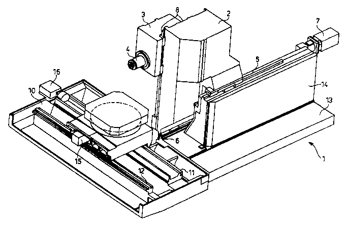
Fig. 1 shows a perspective view of the column-type machine
tool according to the invention with removed covers,
and
Fig. 2 shows a perspective view of the column-type machine
tool according to the invention from another angle
with covers shown on the guideways.
A machine bed designated in general by the designation 1
consists of a horizontal base plate 13 and an approximately
perpendicular plate 14 which is arranged thereon and forms a
supporting structure.
A column 2 is guided by means of a guideway 6 on an edge
of the base plate 13 and approximately at half the height by
means of a guideway 5 on the top edge of the perpendicular
plate 14. The bottom guideway 6 is arranged below the column

'' ' CA 02421616 2003-02-26
- 4 -
2 approximately in its perpendicular center-of-gravity plane,
whereas the top, lateral guideway 5 lies approximately at
half the height of the column 2.
On the column 2, a tool carrier 3 is perpendicularly
traversable on guideways 8 by means of a traverse drive 17.
In the exemplary embodiment shown, the tool carrier 3 is
designed as a headstock and carries a work spindle 4, which
if need be can be designed to be axially traversable in the
tool carrier 3.
The work spindle 4 may be designed for mounting milling
cutters or angular milling heads. Likewise, a face plate can
be attached to the work spindle 4. Finally, the work spindle
4 may also be designed as a tool slide for mounting a turning
tool if a workpiece is to be machined on the rotary table 9
arranged in front of it in the manner of a vertical lathe.
A traverse drive 7 engages on the column 2 at the level
of the top guideway 5, so that high acceleration and
deceleration rates can be achieved without a substantial
tilting moment acting on the column.
By means of guideways 11, 12, the rotary table 9 is
traversable on a bed 10 transversely to the direction of
movement of the column 2. A traverse drive 16 is provided for
this purpose. A rotary drive 15 serves to rotate the rotary
table 9, either for the angular positioning of a workpiece on
the rotary table 9 or as a rotary drive for the rotary table
9 if a workpiece arranged thereon is to be machined in a
rotary manner by means of a turning tool.
A top, sloping telescopic cover 18 for the top guideway
5, a sloping, fixed cover plate 19 and a bottom, sloping
telescopic cover 20 for the bottom guideway 6 can be seen in
fig. 2. Chips thrown against the covers 18, 19, 20 during the
machining of a workpiece are directed into a chip trough 21
below a tool carrier. A flat telescopic cover 20 protects the
guideways 8 on the column 2 from contamination by chips.
Roof-shaped telescopic covers 23 are arranged over the
guideway 11 for the rotary table 9 on both sides of the

CA 02421616 2003-02-26
_ 5 _
latter, whereas sloping telescopic covers 24 are sufficient
for the guideway 12.
A chip trough 25 is formed on that side of the roof-
shaped telescopic covers 23 which faces the column 2, whereas
a further chip trough 26 is formed between the roof-shaped
telescopic covers 23 and the sloping telescopic covers 24.
The chips in these chip troughs 25, 26 are removed by chip
conveyors 27, 28. The chips in the chip trough 21 are
transported into the chip trough 25 by means of a chip
conveyor (not shown) and are removed therefrom, as already
mentioned, by the chip conveyor 27.

Representative Drawing
A single figure which represents the drawing illustrating the invention.
Administrative Status

2024-08-01:As part of the Next Generation Patents (NGP) transition, the Canadian Patents Database (CPD) now contains a more detailed Event History, which replicates the Event Log of our new back-office solution.

Please note that "Inactive:" events refers to events no longer in use in our new back-office solution.

For a clearer understanding of the status of the application/patent presented on this page, the site Disclaimer , as well as the definitions for Patent , Event History , Maintenance Fee  and Payment History  should be consulted.

Event History

Description Date
Time Limit for Reversal Expired 2007-10-05
Application Not Reinstated by Deadline 2007-10-05
Inactive: Abandon-RFE+Late fee unpaid-Correspondence sent 2006-10-05
Deemed Abandoned - Failure to Respond to Maintenance Fee Notice 2006-10-05
Letter Sent 2006-05-02
Inactive: Single transfer 2006-03-14
Letter Sent 2004-05-04
Inactive: Transfer information requested 2004-04-28
Inactive: Correspondence - Transfer 2004-04-07
Inactive: Single transfer 2004-03-11
Inactive: IPRP received 2003-07-28
Inactive: Courtesy letter - Evidence 2003-06-10
Inactive: Cover page published 2003-06-09
Inactive: Notice - National entry - No RFE 2003-06-04
Application Received - PCT 2003-04-03
Inactive: IPRP received 2003-02-27
National Entry Requirements Determined Compliant 2003-02-26
Application Published (Open to Public Inspection) 2002-04-18

Abandonment History

Abandonment Date Reason Reinstatement Date
2006-10-05

Maintenance Fee

The last payment was received on 2005-09-21

Note : If the full payment has not been received on or before the date indicated, a further fee may be required which may be one of the following

  • the reinstatement fee;
  • the late payment fee; or
  • additional fee to reverse deemed expiry.

Patent fees are adjusted on the 1st of January every year. The amounts above are the current amounts if received by December 31 of the current year.
Please refer to the CIPO Patent Fees web page to see all current fee amounts.

Fee History

Fee Type Anniversary Year Due Date Paid Date
Basic national fee - standard 2003-02-26
MF (application, 2nd anniv.) - standard 02 2003-10-06 2003-09-17
Registration of a document 2004-03-11
MF (application, 3rd anniv.) - standard 03 2004-10-05 2004-09-03
MF (application, 4th anniv.) - standard 04 2005-10-05 2005-09-21
Registration of a document 2006-03-14
Owners on Record

Note: Records showing the ownership history in alphabetical order.

Current Owners on Record
DORRIES SCHARMANN TECHNOLOGIES GMBH
Past Owners on Record
BERND STUDEMANN
WERNER JODL
Past Owners that do not appear in the "Owners on Record" listing will appear in other documentation within the application.
Documents

To view selected files, please enter reCAPTCHA code :


To view images, click a link in the Document Description column. To download the documents, select one or more checkboxes in the first column and then click the "Download Selected in PDF format (Zip Archive)" or the "Download Selected as Single PDF" button.

List of published and non-published patent-specific documents on the CPD .

If you have any difficulty accessing content, you can call the Client Service Centre at 1-866-997-1936 or send them an e-mail at CIPO Client Service Centre.


Document
Description 
Date
(yyyy-mm-dd) 
Number of pages   Size of Image (KB) 
Description 2003-02-25 6 238
Claims 2003-02-25 3 99
Abstract 2003-02-25 2 76
Representative drawing 2003-02-25 1 33
Drawings 2003-02-25 2 68
Reminder of maintenance fee due 2003-06-08 1 106
Notice of National Entry 2003-06-03 1 189
Request for evidence or missing transfer 2004-02-29 1 103
Courtesy - Certificate of registration (related document(s)) 2004-05-03 1 106
Courtesy - Certificate of registration (related document(s)) 2006-05-01 1 128
Reminder - Request for Examination 2006-06-05 1 116
Courtesy - Abandonment Letter (Request for Examination) 2006-12-13 1 167
Courtesy - Abandonment Letter (Maintenance Fee) 2006-11-29 1 175
PCT 2003-02-25 14 561
Correspondence 2003-06-03 1 24
PCT 2003-02-26 5 204
PCT 2003-02-26 7 322