Note: Descriptions are shown in the official language in which they were submitted.
CA 02421675 2003-03-11
AUTOMATIC RESTACICING TRAY SIDE GUIDE REPOSITIONING SYSTEM
PROVIDING SHEET STACWCING SCATTER REDUCTION
Disclosed herein is a simple and low cost system for automatically resetting
one or both side guides of a sheet stacking tray in coordination and
s correspondence with the positioning of the side guides) of a sheet input
firay (of a
document handier input tray or a print media sheet input tray) to accommodate
changes in the sizes of the sheets being fed and stacked, and to reduce output
stack sheet scattering, especially skewed sheets stacking.
In the specific disclosed embodiment, the lateral setting (repositioning) of
as the (existing) variable position side guide in the input tray of a document
handler
(DH) to the sides) of a stack of input sheets automatically correspondingly
resets
a side guide of an underlying (or overlying) output stacking tray, to reduce
output
stack sheet scattering (skewed stacking). In this embodiment, this is
accomplished by a simple direct mechanical integration of these respective
side
is guides of the respective trays or bins. ~lny increase in lJfVIC is very
small in the
disclosed embodiment, since no additional sensors, motors, or solenoids are
required.
By way of background, heretofore, normally a sheet output stacking tray
does not have any variable position side guides. A key reason is that
resetting
2o such guides in an output stacking tray to a proper position that would not
interfere
with the stacking of larger (wider) shEets without overlapping the side guides
or
stubbing on them, would be too likely to be overlooked when an operator
changes
the size of the input sheets. It would require the operator to remember an
extra,
non-intuitive operation.
2s In the embodiment herein, there is shown an method and apparatus for
controlling and reducing lateral sheet scatter in the output stack for various
paper
sizes by paper guides) which move together with, and may be directly
mechanically attached to, the feedertinput paper guide(s). Adjustment of the
input
tray side guides automatically results in a corresponding adjustment of the
output
CA 02421675 2003-03-11
fray guides positioning. This disclosed system is suitable for various
document
handlers for document imaging systems andlor printers or multifunction
machines,
especially where a sheet input and output tray are in close proximity andlor
superposed. It may be used with either separate or integral input and output
trays.
s One example of a prior art document handler with an input tray with
adjustable side guides, of the type in which the two side guides are linked by
a
rack and pinion mechanism to move toward or away from each other by the same
amount, to provide centered sheet feeding, is shown in Xerox Corp. U.S. Patent
No. 5,946,527 (Attorney Docket IVo. D197573). Two of its figures are provided
to herein, labeled "Prior Art."
The present system can provide improved sheet stacking at lower speeds
as well as higher speeds. By way of furfher background, as sheet feeding and
stacking is desired at higher rates of speed, for example, to provide the
feeding
and scanning of original documents at rates of 120 documents per minute, or
the
is like, the dif~icuity in neatly restacking the sheets is greatly increased.
This is due
to various efFects, increasing with the velocity and sequential rate of the
sheets
being ejected into the output tray. For example, normal size sheets being
outputted at an exemplary 120 documents per minute sequential rate may have a
velocity of about 5.4 cmlsec. This may even cause what is called "airplaning,"
2o especially of sheets with curled lead edges. Sheets being ejected to stack
tend to
"float," due to air trapped under a sheet. The ejected sheet tends to drop
onto the
top of the underlying sheets of the output stack relatively slowly due to the
relatively small force provided by gravity, especially for lighter weight
sheets, as
compared to the resistance of the air under the sheet. A high stacking rate
2s provides very little inter-document time for the sheet to settle neatly
before the
next sheet enters the output tray, and the incoming sheet may slide laterally
relative to the preceding sheet, or even impact it. Also, heavier sheets have
higher kinetic energy. Thus, without additional physical stacking assistance,
sheets being stacked in an output tray at a high rate of speed tend to form an
so unacceptably scattered stack, especially if not lateral conned during their
settling.
CA 02421675 2003-03-11
The term "scattered" herein includes, but is not limited to, sheets being
unacceptably skewed relative to one another andlor being unacceptably
laterally
displaced from one another, as compared to being neatly superposed.
As noted, manually operator adjusted output stacking side guides and end
s guides can reduce such sheet scattering, but this has a significant
disadvantage in
the prior art. Namely, every time the lateral size of the sheets being fed in
from
the input tray changes, the operator must remember to also reset the side
guides
of the output tray to the same sheet dimension, or risk sheet jams or other
problems. Hence, as in the above-cited and other such patents, often no
io repositionable side guides at all are provided in the output stacking tray.
Or,
electromechanical lateral side edge and or end of stack tampers are provided,
at
additional cost and complexity.
In this particular patent they word "imaging system" is being used broadly to
encompass various conventional or other image reading or image printing
is systems. For example, image reading systems include conventional CCD array
imaging bars, such as used in various commercially available document
scanners,
digital copiers, facsimile machines, or multifunction devices. However, in
this
application the term "imaging system" is being more broadly used to also
encompass various image printing systems, such as the print heads of inkjet
~o printers, xerographic printers, or other conventional image printing
systems. Since
these, and various sheet feeders, are all well known per se, they need not be
described herein. This term "imaging system" is being more broadly used herein
because the present system is suitable for either the feeding, image
capturing, and
restacking of original documents; or the feeding, printing and stacking of
blank
2s sheets. In both cases, the same type of sheets may need to be handled. That
is,
both may involve feeding of varying dimensions of paper or plastic print media
sheets into an apparatus and their stae.king in a sheet stacking output tray.
In both
cases, sheet scatter problems can be encountered if the sheets are not
properly
laterally confined during restacking after ejection into an output stacking
tray.
3
CA 02421675 2003-03-11
In the disclosed embodiment, the above and other problems are overcome
by vertical side guides in the output tray, at least one of which
automatically moves
in coordination with the setting of the input tray document stack side
guide(s).
One or both input tray side guides may be conventionally set by the operator
by
s moving them against the sides of a stack of input documents. In the
disclosed
system this also automatically resets output tray side guides surfaces to a
corresponding position in which the inputted sheets will neatly output stack
in the
output tray between output tray side guides which are automatically set to
that
same lateral sheet dimension, thereby reducing the opportunity for those
outputted
to sheets to settle randomly.
As shown and described in the disclosed embodiment, the side guides of
the output tray can even desirably be a simple integral extension or part of
the
input tray side guides, at little additional cost, without requiring any
motors or
sensors, and without requiring any operator resetting of these output tray
side
is guides.
As disclosed herein, the vertical side guides of the input tray may be
connected to one another through a conventional rack-and-pinion system, as
illustrated in prior document handler patents, such the above-cited Xerox
Corp.
U.S. Patent No. 5,946,527 (or others) and its corresponding Figs. 3 and 4 here
20 labeled "Prior Art." Thus, operator resetting of the sheet-retaining space
between
the two side guides of the input tray can be accomplished by operator movement
of one of them. lnlhile fully compatible therewith, the present system is not
limited
thereto, especially since this is a "center registered" system, whereas other
systems are "side registered."
2s Although in the disclosed embodiment a "center registered" system is
provided, in which two side guides of the input 'tray can move towards or away
from each other (i.e., both side guides can move), that this is not required.
There
are alternative systems which can also be provided with the disclosed system,
and
are intended to be covered by the claims, in which one side guide is a fixed
side
4
CA 02421675 2003-03-11
wall and only the opposite side guide is moveable, to provide an "edge
registered"
system instead of a "center registered" system.
It will also be noted that the disclosed lower or output tray side stacking
guides may, as shown, be positioned downstream or upstream of the upper or
s input tray side stacking guides by the disclosed system to provide
additional
design flexibility and a more preferred position of the side guides for both.
This is
also a matter of design choice.
A specific feature of the specific embodiments) disclosed herein is to
provide a print media sheet handling and imaging system with a sheet input
tray, a
to sheet feeder, and a sheet stacking output tray, wherein said print media
sheets of
varying lateral dimensions may be sequentially fed from said sheet input tray
by
said sheet feeder to said imaging system and then ejected into said sheet
stacking
output tray for stacking superposed therein, wherein said sheet input tray has
at
least one laterally repositionable sheet side guide which is repositionable to
said
Is varying lateral dimensions of said print media sheets which are being fed
from said
sheet input tray by said sheet feeder to said imaging system; and wherein said
sheet stacking output tray has at least one laterally repositionable sheet
side guide
repositionable to said varying lateral dimensions of said print media sheets
which
are being fed from said sheet input tray by said sheet feeder to said imaging
2o system; and wherein said at least one laterally repositionable sheet side
guide of
said sheet stacking output tray is automatically IatE~rally repositioned by
said lateral
repositioning of said sheet side guide in said sheet input tray into a
position
providing sheet stacking scatter reduction of said print media sheets of
varying
lateral dimensions being ejected into said sheet stacking output tray for
stacking
2s superposed therein.
Further specific features disclosed in the embodiments) herein, individually
or in combination, include those wherein said at least one laterally
repositionable
sheet side guide of said sheet stacking output tray is mechanically connected
to
move with said at least one laterally repositionable sheet side guide of said
sheet
3o input tray, andlor said at least one laterally repositionable sheet side
guide of said
s
CA 02421675 2003-03-11
sheet stacking output tray is an integral extension of said at least one
laterally
repositionable sheet side guide of said sheet input tray, and/or wherein said
sheet
feeder is feeding said print media sheets at a rate of approximately '120
sheets per
minute or faster, and/or wherein said print media sheets are image bearing
sheets
s and said imaging system is digitally scanning said image bearing sheets,
andlor
wherein said print media sheets are being printed by said imaging system,
and/or
wherein said sheet input tray and said sheet stacking output tray are
superposed
and said at least one laterally repositionable sheet side guide of said output
tray is
a downward extension of said at least one laterally repositionable sheet side
guide
to of said sheet input tray, andlor wherein said at least one laterally
repositionable
sheet side guide of said output tray and said at least one laterally
repositionable
sheet side guide of said sheet input tray are both horizontally and vertically
offset
relative to one another.
As to specific components of the subject system, or alternatives therefor, it
Is will be appreciated that, as is normally the case, some such components are
known per se in other apparatus or applications, which may be additionally or
alternatively used herein, including those from art cited herein. For example,
it will
be appreciated by engineers and others that many of the particular components
illustrated or suggested herein are merely exemplary, and that the same novel
2o motions and functions can be provided by many other known or readily
available
alternatives. Ail cited references, and their references, are incorporated by
reference herein where appropriate for teachings of additional or alternative
details, features, andlor technical background. What is well known to those
skilled
in the art need not be described herein.
as Various of the above-mentioned and further features and advantages will
be apparent to those skilled in the art from the specific apparatus and its
operation
or methods described in the one example below, and the claims. Thus, the
present invention will be better understood from this description of these
specific
embodiment(s), including the drawing figures (which are approximately to
scale)
3o wherein:
6
CA 02421675 2003-03-11
Fig. 1 is a frontal view, partially broken away to illustrate one side of the
exemplary integrated sheet side guides system for the input and output trays
illustrated as part of an exemplary document handling system;
Fig. 2 is a perspective view of the system of Fig. 1;
s Fig. 3 is the same view as Fig. 2, showing different spacing of the side
guides for different size sheets;
Fig. 4, labeled "prior art," is one of the above-described figures from the
above-cited document handler patent, in a top view; and
Fig. 5, also labeled "prior art," is another, perspective, figure copied from
~o the above-cited document handler patent.
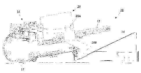
Describing now in further detail the exemplary embodiment with reference
to the Figures, there is shown in Figs 1 and 2 a document handler (DH) 10, by
way of one example of the application of one example of the subject integrated
sheet side guides system. It will be appreciated that numerous other
variations
is are possible, as illustrated by the above-cited and other patents.
In this exemplary DH 10, a document input tray 12 is superimposed over a
document output sheet stacking tray 14. Sheets are sequentially fed from the
document input tray 12 by and through a sheet feeding system 16, which feeds
the
sheets past a document imaging system 17, as described above. Then the
2o documents may be ejected (or inverted and then ejected) into the output
tray 14.
Moveable side guides 20 and 22 are provided for setting to the size of the
documents being fed in the document input tray 12. Specifically, upper
portions
20A and 22A of these side guides 20, 22 are positioned to engage the sides of
the
stack of sheets in the input tray 12. However, here these movable side guides
20,
2s 22 have lower extensions 20B and 22B (the lower extension 20B is
illustrated in
Fig. 1), which extend down through input tray 12 apertures 12A, 12B into the
output tray 14. In the output tray 14, these lower extensions 20B and 22B of
side
guides 20 and 22 provides vertical side guides for the sheets being output
stacked
in the output tray 14.
7
CA 02421675 2003-03-11
It may be seen that whenever the upper portions 20A, 22A of the side
guides 20, 22 are manually reset by the operator, this moves by the same
distance
and position the lower extensions 20B and 22S thereof to automatically reset
those side guides for the output stacking tray 14 to the same dimension of
sheets
s as are being inputted from the input tray 12. This automatically provides
effective
control over sheet scattering in the output tray 14, yet avoids the addition
of
another operator adjustment which may easily be forgotten by an operator. Yet
these automatic features can be provided at very little incremental cost.
An operator will almost always have to open the input tray side or edge
zo guides 20A, 22A wide enough to accommodate loading wider sheets in the
input
tray 12. That will automatically here also widen the lower or output tray 14
side
guides by the same amount to allow proper stacking in between them. See the
difference between Figs. 2 and 3. Even if an operator fails to properly re-
adjust
the input tray guides 20A, 22A more closely together against the sides of a
Is narrower stack of input sheet, so that those upper side guides 20A, 22A are
too far
apart, this will only allow a correspondingly extra opening between the output
tray
side guides, so they would not actually interfere with stacking.
As also shown in this embodiment, the output stacking tray may have a
substantial enough inclined angle from the horizontal, e.g. 25° or
more, so as to
2o allow the documents being outputted into the output tray to slide back down
toward the front vertical wall of the output tray and stack properly in the
feeding or
process direction. Again, while not required, this provides further
cooperation with
the subject automatically re-adjustable side guides for improved uniformity of
output stacking of the ejected sheets.
2s ~/llhile the embodiment disclosed herein is preferred, it will be
appreciated
from this teaching that various alternatives, modifications, variations or
improvements therein may be made by those skilled in the art, which are
intended
to be encompassed by the following claims.