Language selection

Search

Patent 2421908 Summary

Third-party information liability

Some of the information on this Web page has been provided by external sources. The Government of Canada is not responsible for the accuracy, reliability or currency of the information supplied by external sources. Users wishing to rely upon this information should consult directly with the source of the information. Content provided by external sources is not subject to official languages, privacy and accessibility requirements.

Claims and Abstract availability

Any discrepancies in the text and image of the Claims and Abstract are due to differing posting times. Text of the Claims and Abstract are posted:

  • At the time the application is open to public inspection;
  • At the time of issue of the patent (grant).
(12) Patent: (11) CA 2421908
(54) English Title: INDICATING LIGHT
(54) French Title: VOYANT
Status: Deemed expired
Bibliographic Data
(51) International Patent Classification (IPC):
  • H05B 33/00 (2006.01)
  • F21S 8/00 (2006.01)
  • G08B 5/36 (2006.01)
  • H01L 33/00 (2010.01)
  • F21V 25/02 (2006.01)
  • H01L 33/00 (2006.01)
(72) Inventors :
  • BARLIAN, REINHOLD (Germany)
  • LUX, KARL-HEINZ (Germany)
(73) Owners :
  • BARTEC COMPONENTEN UND SYSTEME GMBH (Germany)
(71) Applicants :
  • BARTEC COMPONENTEN UND SYSTEME GMBH (Germany)
(74) Agent: RIDOUT & MAYBEE LLP
(74) Associate agent:
(45) Issued: 2009-03-10
(22) Filed Date: 2003-03-13
(41) Open to Public Inspection: 2003-09-13
Examination requested: 2007-01-22
Availability of licence: N/A
(25) Language of filing: English

Patent Cooperation Treaty (PCT): No

(30) Application Priority Data:
Application No. Country/Territory Date
P10210919 Germany 2002-03-13

Abstracts

English Abstract

An indicating light for an optical display is disclosed and comprises a housing with electrical lead parts and a light-emitting diode arranged in a light rod The light rod has a translucent round head An inner side of the round head faces the light-emitting diode and has a refracting fine pearl structure.


French Abstract

Un voyant pour un affichage optique est divulgué et comprend un boîtier avec des parties de connexion électrique et une diode émettrice de lumière disposée dans une baguette lumineuse. La baguette lumineuse a une tête ronde translucide. Un côté intérieur de la tête ronde fait face à la diode électroluminescente et a une structure de perles fines réfringente.

Claims

Note: Claims are shown in the official language in which they were submitted.


We claim:

1. Indicating light for optical display, comprising a housing with electrical
lead parts, a
light-emitting diode arranged in a light rod which has a translucent round
head, an inner
side of which facing the light-emitting diode has a refracting fine pearl
structure.

2. Indicating light according to claim 1, wherein at least the round head of
the light rod
has a milky tinge.

3. Indicating light according to claim 1, wherein at least the round head of
the light rod is
of a fluorescent milky colour.

4. Indicating light according to claim 1, wherein the light rod is formed in
one piece with
the round head and from the same material.

5. Indicating light according to claim 1, wherein the light rod is formed as a
cylindrical
tube, one end of which is closed by the round head.

6. Indicating light according to claim 1, the light rod is fixed in the
housing by a tube end
section of the light rod which is away from the round head.

7. Indicating light according to claim 1, wherein a printed circuit board
having the light-
emitting diode and electronic components arranged thereon is provided within
the light
rod.

8. Indicating light according to claim 1, wherein a front casing is attachable
to a
mounting wall which is arranged between a front ring and a threaded nut
located at an
insert housing.

9. Indicating light for optical display, comprising a housing with electrical
lead parts, and
a light-emitting diode arranged in a light rod which has a translucent round
head, an inner
side of which facing the light-emitting diode has a refracting fine pearl
structure, wherein
part of the light rod in the housing is cast over with moulding resin for
explosion
protection purposes.

10. Indicating light for optical display, comprising a housing with electrical
lead parts,
and a light-emitting diode arranged in a light rod which has a translucent
round head, an
inner side of which facing the light-emitting diode has a refracting fine
pearl structure,
wherein the light rod is constucted as a pressure-resistant capsule for the
purpose of
explosion protection.

11. Indicating light for optical display, comprising a housing with electrical
lead parts, a
light-emitting diode arranged in a light rod which has a translucent round
head, an inner
side of which facing the light-emitting diode has a refracting fine pearl
structure, wherein
the housing is closed by a cover into which the light rod protrudes.


12. Indicating light for optical display, comprising a housing with electrical
lead parts,
and a light-emitting diode arranged in a light rod which has a translucent
round head, an
inner side of which facing the light-emitting diode has a refracting fine
pearl structure,
wherein a printed circuit board is securely located in a position between
holding ribs in
the light rod.

13. Indicating light for optical display, comprising a housing with electrical
lead parts,
and a light-emitting diode arranged in a light rod which has a translucent
round head an
inner side of which facing the light-emitting diode has a refracting fine
pearl structure,
wherein a front casing extends over the part of the light rod which protrudes
past a cover
of the housing.

14. Indicating light for optical display, comprising a housing with electrical
lead parts,
and a light-emitting diode arranged in a light rod which has a translucent
round head, an
inner side of which facing the light-emitting diode has a refracting fine
pearl structure,
wherein a front casing has a translucent light cap extending over the round
head of the
light rod.

15. Indicating light for optical display, comprising a housing with electrical
lead parts,
and a light-emitting diode arranged in a light rod which has a translucent
round head, an
inner side of which facing the light-emitting diode has a refracting fine
pearl structure,
wherein an inner side of a light cap facing the round head of the light rod
has a refracting
fine pearl structure.

16. Indicating light for optical display according to claim 15 wherein the
fine pearl
structure on the inside surface of the light cap and the fine pearl structure
on the inner
side of the round heard are essentially identical.

17. Indicating light for optical display, comprising a housing with electrical
lead parts, a
light-emitting diode arranged in a light rod which has a translucent round
head, an inner
side of which facing the light-emitting diode has a refracting fine pearl
structure, and a
light cap having a milky or milky/coloured fluorescent tint.

18. Indicating light for optical display, comprising a housing with electrical
lead parts, a
light-emitting diode arranged in a light rod which has a translucent round
head, an inner
side of which facing the light-emitting diode has a refracting fine pearl
structure, wherein
the round head of the light rod and a light cap are tinted to suit a
wavelength of the light
colour of the light-emitting diode.

19. Indicating light for optical display, comprising a housing with electrical
lead parts, a
light-emitting diode arranged in a light rod which has a translucent round
head, an inner
side of which facing the light-emitting diode has a refracting fine pearl
structure, and a
light cap held by a front ring which can be attached at an insert housing.

20. An indicating light for an optical display, comprising a housing;
electrical lead parts
disposed in the housing; a light rod; a light-emitting diode arranged in the
light rod,


wherein the light rod has a translucent round head and wherein an inner side
of the
translucent round head facing the light-emitting diode has a refracting fine
pearl structure.
21. Indicating light according to claim 20 wherein the housing includes a foot
section
fastened to a sectional rail.

22. Indicating light according to claim 20 wherein the light rod comprises a
rectangular
tubular section fixed in the housing, wherein the tubular section is disposed
relatively
remote from the round head and comprises a rectangular dimension larger than a
dimension of the remaining part of the light rod and forms a shoulder at the
beginning of
the tubular section, wherein in an area near the shoulder, the light rod is
surrounded by a
cast molding resin, extending into the shoulder.

23. Indicating light according to claim 22 wherein the light rod is made of an
opaque
material and the light rod is a solid piece of material, with a wall thickness
both at the
round head and at the tubular section, and between the round head and the
tubular section
which is essentially constant.

24. Indicating light according to claim 20 wherein at least the inner side of
the round
head, facing the light-emitting diode, is of a fine pearl-shaped structure,
not smooth but
finely roughened by erosion, etching, grit blasting or any other appropriate
forming of the
mould surface, to allow a multitude of globular or pearl-shaped elevations,
alternating
with a multitude of small troughs being directly located next to each other,
wherein any
light emitted by the light-emitting diode will diffract and be captured on the
entire inner
side of the round head, thus making the round head as such shine as a uniform
large
luminous element.

25. Indicating light according to claim 21 wherein the indicating light
further comprises a
front casing, covering a part of the light rod projecting from a cover,
wherein the front
casing comprises an insert housing surrounding the light rod like a tube and a
light cap,
attached to the insert housing by means of a front ring, and wherein a sealing
ring is
arranged between an edge of the light cap and the insert housing, and wherein
the light
cap is made of an opaque material and covers the round head, leaving a small
clearance.
26. Indicating light according to claim 25 wherein an inside of the light cap,
facing the
round head, is of a fine pearly-shaped structure essentially identical with a
finely
roughened internal structure of the round head and made by an identical
production
process to cause a multitude of small pearl-shaped elevations and a multitude
of small
troughs to be alternately directly positioned next to each other, thus finely
roughening the
inside of the light cap, and wherein the light cap is coloured diffusely milky
or
milky/coloured and fluorescent, in order to reduce its translucency, with an
inherent shine
of the light cap and more even and intensive lighting being achieved.

27. Indicating light according to claim 25 wherein both the round head of the
light rod
and the light cap are coloured according to light and colour wavelengths of
the light-
emitting diode, to achieve an optimally even and uniform lighting.


28. An indicating light for an optical display, comprising a housing;
electrical lead parts
disposed in the housing; a tubular light rod; a light-emitting diode arranged
in the tubular
light rod; and a translucent round head which closes the tubular light rod,
wherein an
inner side of the translucent round head facing the light-emitting diode has a
multitude of
small globular elevations or small troughs directly located next to each
other.

29. An indicating light for an optical display, comprising a housing;
electrical lead parts
disposed in the housing; a tubular light rod having a round head; a light-
emitting diode
arranged in the tubular light rod, an insert housing surrounding the light
rod; and a light
cap attached to the insert housing by means of a front ring, wherein the light
cap covers
the round head with a small clearance, and an inner side of the light cap
facing the round
head has a multitude of small globular elevations or small troughs directly
located next to
each other.

30. An indicating light for an optical display, comprising a housing;
electrical lead parts
disposed in the housing; a tubular light rod; a light-emitting diode arranged
in the tubular
light rod; and a translucent round head which closes the tubular light rod,
wherein an
inner side of the translucent round head facing the light-emitting diode has a
multitude of
small globular elevations or small troughs directly located next to each
other; an insert
housing surrounding the light rod, and a light cap attached to the insert
housing by means
of a front ring, wherein the light cap covers the round head with a small
clearance, and an
inner side of a light cap facing the round head has a multitude of small
globular
elevations or small troughs directly located next to each other.

Description

Note: Descriptions are shown in the official language in which they were submitted.


CA 02421908 2007-11-01
Indicating light

The invention refers to an indicating light for optical display. Most prior
art indicators, equipped with light-eniitting diodes, suffer of inadequate
light

distribution and uneven lighting, thus making indicators worse than comparable
lighting
systems based on incandescent lamps. There are various types of light-emitting
diodes
resulting in highly variable lighting pattems. A light-enlitting diode having
a tight lighting angle will generate light, sharp spot lighting but no surface
ligliting. A light-emitting diode

having a wide lighting angle will generate sufficient brightness, in order to
meet requirements
for emitting a clear signal. It is prior art to use a printed circuit board
having a multitude of
light-emitting diodes bonded to it, a so-called multi-LED. However, this
variation is relatively
expensive, and irrespective of its price, only marginally better lighting will
be the result. In addition, it will geilerate much heat, thus limiting its use
in explosive atmospheres, based on

staiidard specifications in accordance with DIN EN 50014/18/19. In addition,
it is a known fact
that standard light-emitting diodes must be arranged in circles and must
provide a lighting area
comprising a multitude of small lenses. Alternating light and dark spots
occurring in this,
however, are a nuisance, in particular when symbols or letters are arranged on
the lighting
surface. Furthermore, this arrangement is expensive.

It is the object of the present invention to create an indicating light for
optical display, offering
a high functionality by simple means, based on a low operating temperature and
bright and
even lighting.

An indicating light for all optical display is disclosed. The indicating light
coinprises a
housing with electrical lead parts, a light-emitting diode arranged in a light
rod with a
translucent round head. The inner side facing the light-emitting diode has a
refracting fme
pearl structure.


CA 02421908 2003-03-13
2

it is the object of the present invention to create ati iridicatiny fiytit rur
uptit;al ctisplay,
offering a high functionality by simple means, based on a low operating
temperature
and bright and even lighting.

This object of the invention has been solved by the features of Claim 1.

Preferred embodiments and developments of the invention are characterised by
the
features of the subclaims,

ror othcr bor+cfits and cssGntiai dctails of the invcntion, scQ the fo[fvwing
specifcation and the drawing, showing as an example a preferred embodiment in
a
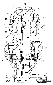
single schematic section.

The indicating light according to the invention comprises a housing 1,
including a
cover 2 and a foot section 3 that may be fastened to a sectional rail not
shown here.
The housing I compr-ses eiectrically conducting components 4 for thc
connection of
electrical supply and terminal leads andlor connecting terminals.

in acfdition, tho housing 1 camprisHS e light rod 5, made of an opaque
material,
predominantly designed as a circular cylindrical tube extending through the
cover
and projocting over it. The part of the light rod 5 within the housing 1
comprises a
rectangular tubular section 6 anchored in the housing 1, the rectangular
dimension of
which Is somewhat larger than the remaining part of the light rod 5. At the
beginning
of the tubular section 6, a shoulder 7 is formed because of the larger
rectangular
ciimension. In thiS area, thQ light rod 5 has been surrounded by a moulding
resin 8,
extending into the shoulder 7. The moulding resin 8 has been cast to comply
with
standard requirements of explosion protection in accordance with DIN EN
5001 411 819 9.

The end section of the tubular end section 6 located away fresrn the light rod
5, has
been designed as a round head 9, thus closing the tubular light rod 5_ The
light rod 5
is=a soiid picce of matcrial, with the walt thickness both at the round head 9
and the


CA 02421908 2003-03-13
3

tubu{ar end section 6 and between these end sectipns being essentially
identical. For
use in explosive areas, the light rod 5 may be conveniently designed as a
pressure-
resistant capsule In compliarice with the requirements or ttie explvslon
protection
standard DIN EN 50014/18/19,

A circuit board 10 may be arranged within the light rod 5, preferably held
between
web-shaped holding ribs 11. A laght-emitting diode may be arranged on the
circuit
board 10 just below the round head 9 and aligned towards the latter. In
addition, the
circuit board 10 may be provided with electronic components 13 supporting the
function of the light-emitting diode 12_

In order to obtain even and bright lightPng, at loast thc innor sido 14 of tho
round head
9, facing the iight-emitting diode 12, may be of a fine pearl-shaped
structure,
preteranly aeslgnea to aiiow a muttltucie or gaoouiar ano/or peart-snapeca
elevatlons,
alternating with a multitude of small troughs being directly located next to
each other,
thus not making the inner side 14 smooth but finely roughened. A finely
roughened
inner side structure like this may be preferably obtained by erosion, etching,
grit
blasting or any other appropriate design of the mould surface. This finely
roughened
inner side structure has the effect that any iight emitted by the iight-
emitting diode 12
vviii diffract and be captured on the entire inner side 14 of the rOund head
9, thus
making the round head as such shine as a uniform large luminous element.
Moreover, it may be of benefit to colour the light rod 5 but at least the
round head 9,
diffusely milky or milkylColourgd and fluoresc-ant. This colouring would
accentuate
translucency in a manner that a certain inherent shine of the light rod 5
andlor the
round head 9 would occur, thus maicing Iighting more even and lntensive.

As also shown in the drawing, the indicating light may comprise a front casing
15,
covering the part of the light rod 6 projecting from the cover 2. The front
casing 15
comprises an insert housing 16 surrounding the light rod 5 like a tube and a
light cap
17, attached to the insert housing 16 by means of a front ring 18. A sealing
ring 20 is
arranged betwepn the edgP 19 of the light cap 17 and the insert housing 16. A
threaded nut 22 may be rotatably arranged on the insert housing 16 for
attaching the


CA 02421908 2003-03-13
4

front casing 15 in a secure position, duc to bcing firmFy screwed against the
insidc of
the mounting wail 21.

The light cap 17 is made of an opaque material and covers the round head 9,
leaving
a small clearance. The inside 23 of the light cap 17, facing the round head 9,
may
also be of a fine pearly-shaped structure. This structure may be designed to
cause a
multitude of small pearl-shaped elevations and a multitude of small troughs to
be
alternative directly positioned next to each other, thus finely roughening the
inside 23.
This finely roughened inside structure may be essentially identical with the
finely
roughened iraternai strcicture of thhe round cap 9 and may be made by an
identical
production process. In addition, it may also be beneficial to colour the light
cap 17
diffusely milky or milky/coloured and fluorescent, in order to reduce its
#ranslucency,
with an inherent shine of the light cap 17 andlor more even and intensive
iighting
being achieved. In addition, optimally even and uniform lighting may be
achieved by
both the round cap 9 of the light rod 5 and the light cap 17 of the front
casing 15
being coloured according to the light and colour wave lengths of the light-
emitting
diode 12.

Representative Drawing
A single figure which represents the drawing illustrating the invention.
Administrative Status

For a clearer understanding of the status of the application/patent presented on this page, the site Disclaimer , as well as the definitions for Patent , Administrative Status , Maintenance Fee  and Payment History  should be consulted.

Administrative Status

Title Date
Forecasted Issue Date 2009-03-10
(22) Filed 2003-03-13
(41) Open to Public Inspection 2003-09-13
Examination Requested 2007-01-22
(45) Issued 2009-03-10
Deemed Expired 2020-03-13

Abandonment History

There is no abandonment history.

Payment History

Fee Type Anniversary Year Due Date Amount Paid Paid Date
Registration of a document - section 124 $100.00 2003-03-13
Application Fee $300.00 2003-03-13
Maintenance Fee - Application - New Act 2 2005-03-14 $100.00 2005-01-12
Maintenance Fee - Application - New Act 3 2006-03-13 $100.00 2006-03-13
Request for Examination $800.00 2007-01-22
Maintenance Fee - Application - New Act 4 2007-03-13 $100.00 2007-03-13
Advance an application for a patent out of its routine order $500.00 2007-03-19
Maintenance Fee - Application - New Act 5 2008-03-13 $200.00 2008-01-09
Final Fee $300.00 2008-12-15
Maintenance Fee - Application - New Act 6 2009-03-13 $200.00 2008-12-15
Maintenance Fee - Patent - New Act 7 2010-03-15 $200.00 2010-03-08
Maintenance Fee - Patent - New Act 8 2011-03-14 $200.00 2011-03-11
Maintenance Fee - Patent - New Act 9 2012-03-13 $200.00 2012-03-09
Maintenance Fee - Patent - New Act 10 2013-03-13 $250.00 2013-03-12
Maintenance Fee - Patent - New Act 11 2014-03-13 $250.00 2014-03-10
Maintenance Fee - Patent - New Act 12 2015-03-13 $250.00 2015-03-13
Maintenance Fee - Patent - New Act 13 2016-03-14 $250.00 2016-03-14
Maintenance Fee - Patent - New Act 14 2017-03-13 $250.00 2017-03-10
Maintenance Fee - Patent - New Act 15 2018-03-13 $450.00 2018-02-27
Maintenance Fee - Patent - New Act 16 2019-03-13 $450.00 2019-02-28
Owners on Record

Note: Records showing the ownership history in alphabetical order.

Current Owners on Record
BARTEC COMPONENTEN UND SYSTEME GMBH
Past Owners on Record
BARLIAN, REINHOLD
LUX, KARL-HEINZ
Past Owners that do not appear in the "Owners on Record" listing will appear in other documentation within the application.
Documents

To view selected files, please enter reCAPTCHA code :


To view images, click a link in the Document Description column. To download the documents, select one or more checkboxes in the first column and then click the "Download Selected in PDF format (Zip Archive)" or the "Download Selected as Single PDF" button.

List of published and non-published patent-specific documents on the CPD .

If you have any difficulty accessing content, you can call the Client Service Centre at 1-866-997-1936 or send them an e-mail at CIPO Client Service Centre.


Document
Description 
Date
(yyyy-mm-dd) 
Number of pages   Size of Image (KB) 
Abstract 2003-03-13 1 7
Description 2003-03-13 4 198
Claims 2003-03-13 3 102
Drawings 2003-03-13 1 35
Representative Drawing 2003-05-08 1 18
Cover Page 2003-08-20 1 37
Claims 2007-11-01 3 67
Abstract 2007-11-01 1 8
Description 2007-11-01 4 199
Claims 2008-07-30 4 238
Cover Page 2009-02-17 1 43
Prosecution-Amendment 2008-07-30 6 309
Prosecution-Amendment 2007-05-02 2 69
Prosecution-Amendment 2007-04-04 1 12
Fees 2005-01-12 1 27
Assignment 2003-03-13 7 325
Fees 2007-03-13 1 28
Fees 2006-03-13 1 26
Prosecution-Amendment 2007-01-22 1 26
Maintenance Fee Payment 2018-02-27 1 33
Prosecution-Amendment 2007-03-19 2 47
Correspondence 2007-03-19 2 47
Prosecution-Amendment 2007-11-01 8 183
Prosecution-Amendment 2008-01-31 2 40
Fees 2008-01-09 1 28
Correspondence 2008-12-15 1 35
Fees 2008-12-15 1 34
Maintenance Fee Payment 2019-02-28 1 33
Fees 2012-03-09 1 41
Fees 2013-03-12 1 137
Fees 2015-03-13 1 33
Fees 2016-03-14 1 33
Maintenance Fee Payment 2017-03-10 1 33