Note: Descriptions are shown in the official language in which they were submitted.
CA 02421926 2003-03-11
WO 02/22312 PCT/EP01/10071
- 1 -
Clamping tool comprising a displaceable and
repositionable fixed clamping jaw
The invention relates to a clamping tool comprising a
clamping jaw which is mounted in a releasable manner on
a rail, preferably at the end of the latter, by a bolt,
which passes through an opening of the rail, such that,
once the bolt has been drawn out of the opening, it can
be mounted at another location of the rail, preferably
at the other end of the latter, by virtue of the bolt
being inserted into an opening there, on which rail
there is disposed in a displaceable manner a second
clamping jaw which, depending on the arrangement of the
first clamping jaw on the rail, can be moved, by means
of a clamping device, into a clamping position in the
direction of the first clamping jaw or in the direction
away from the same.
Such a clamping tool in the form of a screw clamp is
known from DE 33 47 232 Al. In this document, the
clamping jaw which is firmly connected to the rail is
associated with a clamping-jaw carrier which projects
at right angles from the rail. This clamping-jaw
carrier has a slot. The end of the rail is inserted
into this slot and secured by a bolt, a thumb nut being
screwed onto the thread of this bolt. An opening is
likewise located at the other end of the rail. The
displaceable clamping jaw is likewise seated on a
clamping-jaw carrier. The clamping-jaw carrier can be
displaced with sliding- action on the rail and can
remain there in a tilted position. This tilted position
is achieved if the clamping jaw which is seated at the
end of a screw spindle is moved into a clamping
position in relation to the other, fixed clamping jaw.
For this purpose, the grip seated at the other end of
the spindle is rotated. If the fixed clamping jaw is
mounted on the rail such that the displaceable clamping
jaw is moved toward the fixed clamping jaw by virtue of
CA 02421926 2003-03-11
- 2 -
the clamping device being actuated, then it is possible
for a workpiece to be clamped in between the two
clamping jaws. If, in contrast, the fixed clamping jaw
is fitted on the other side of the rail, so that the
clamping device displaces the displaceable clamping jaw
away from the fixed clamping jaw, then the clamping
tool acts as an expanding tool.
Such a clamping tool is also already known from
DE 197 31 579 Al. In this document, the clamping device
has a step-by-step mechanism by means of which the
entire displaceable clamping-jaw carrier can be moved
along the rail in steps by virtue of a handle being
actuated, the displaceable clamping jaw being moved
away from the fixed clamping jaw or toward the same,
depending on the arrangement of the fixed clamping jaw.
Provision is also made here, by virtue of a bolt which
passes through an opening of the rail being released,
for the clamping-jaw carrier which carries the fixed
jaw to be positioned on one side of the rail or the
other, in order to be mounted there, so that the
clamping tool is capable either of clamping in a
workpiece between the two clamping jaws or of being
positioned with spreading action in an opening of a
workpiece. The clamping tool described here is
additionally provided with a release lever which can
release the two clamping jaws out of the clamping
position. This release lever engages in the step-by-
step mechanism such that, by virtue of the lever being
actuated, it is also possible for the entire clamping
device to be displaced back.
It is an object of the invention to simplify the
operation of changing the fixed clamping jaw from one
mounting location on the rail to the other.
The object is achieved by the invention given in the
claims.
CA 02421926 2003-03-11
- 3 -
Claim 1 provides, in particular, that the bolt is
associated in captive fashion with the first clamping
jaw. It thus cannot be lost once it has been drawn out
of the opening of the rail. The bolt, furthermore, is
retained in the engagement position in the opening by
the force of a spring which is subjected to stressing
when the bolt is displaced out of the opening.
Accordingly, in order to release the fixed clamping jaw
from the rail, all that is necessary is for the bolt to
be displaced counter to the force of the spring. There
is no longer any need for a thumb screw to be loosened,
as is the case in the prior art. The use of a spring
which forces the bolt into the engagement position has
the additional advantage that the positive fit between
clamping-jaw carrier and rail does not have to be
deliberately produced. The bolt enters automatically
into the opening whenever the jaw is pushed over the
rail and the end side of the bolt is aligned with the
opening. As a result of an advantageous development, a
push button is coupled to the bolt such that, by virtue
of pressure being applied to it, the bolt is displaced.
The coupling here is provided such that the pressure
applied to the push button displaces the bolt out of
the opening. As long as the push button is retained in
the pressed-in position, the bolt is in the withdrawn
position. If the push button is released, then the bolt
can enter into the opening if the latter is in
alignment with the bolt. In order to form this
advantageous function, it is particularly advantageous
if the bolt is associated with a U-shaped catch member.
It is preferably formed' by a short leg of this catch
member. The longer leg of the U-shaped catch member
projects through the clamping-jaw carrier such that it
is secured on the underside of the push button, so that
a displacement movement of the longer U-leg is
transmitted, via the U-web, to the short bolt, so that
the latter is drawn out of the opening. The spring,
which retains the short leg of the U-shaped catch
element in the engagement position, is preferably
CA 02421926 2003-03-11
- 4 -
seated in the vicinity of the push button. It may be
located centrally beneath the push button, so that the
resilient mounting for the push button is
simultaneously the resilient mounting for the bolt. The
bolt here preferably projects through the center of a
through-opening for the rail. The length of the U-web
here is selected such that the long U-leg passes
through the jaw carrier outside the rail. In the
locking position, the free end of the bolt may be
located in an opening of the inner through-opening
wall, this avoiding bending of the bolt as a result of
the advantageous introduction of force during clamping.
In order to achieve an arrangement of the push button
which is advantageous in terms of actuation, the longer
U-leg is seated eccentrically, rather than centrally,
on the push button. As a result, for all practical
purposes, the push button is located in an overlapping
position with the rail. It is also possible for a
penetrating extension to be disposed on the rear side
of the push button, on which the spring and the longer
U-leg is seated. The spring may be seated between this
penetrating extension and the longer U-leg. With the
push button retained in the pushed-in position, the
extension is located in a broad-side recess of the
first jaw, which is located beneath the push button.
The push button may be provided as an exposed part.
Provision is also made, however, for the push button to
be located in a cup-like opening of the broad side of
the clamping-jaw carrier. This prevents undesired
actuation of the push button. The cup-like opening may
be enclosed by the wall of a sleeve. In the locking
position, the end border of this sleeve is aligned with
the surface of the push button. The web, which is
located opposite the push button and connects the push
rod to the bolt, is likewise located in a housing
recess. Provision is also made here for the end border
of the wall of this housing recess to be aligned with
the surface of the web.
CA 02421926 2003-03-11
- 5 -
Exemplary embodiments of the invention are explained
hereinbelow with reference to attached drawings, in
which:
figure 1 shows a first exemplary embodiment of the
invention, in the case of which the clamping
tool is a screw clamp,
figure 2 shows the exemplary embodiment according to
figure 1 with the fixed clamping jaw turned
round,
figure 3 shows a side view of the fixed clamping jaw,
figure 4 shows a front view of the fixed clamping jaw,
figure 5 shows a rear view of the fixed clamping jaw,
figure 6 shows a section along line VI-VI in figure 2,
figure 7 shows an illustration according to figure 6
with the push button pressed in,
figure 8 shows a section along line VIII-VIII in
figure 6,
figure 9 shows a second exemplary embodiment of the
invention, in the case of which the clamping
tool is formed as a one-hand clamp clip with
a rearward displacement function,
figure 10 shows a further exemplary embodiment of a
displaceable clamping jaw, in side view,
figure 11 shows a sectional illustration, similar to
figure 6, of the exemplary embodiment
illustrated in figure 10,
figure 12 shows a plan view of the push button, and
CA 02421926 2003-03-11
- 6 -
figure 13 shows a bottom view of the web.
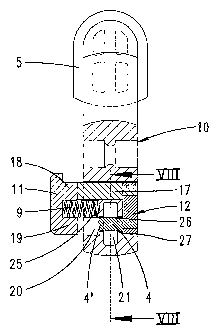
The clamping tool according to the invention has a rail
1 onto which a displaceable clamping jaw 7 can be
displaced. A fixed clamping jaw 5 is disposed opposite
the displaceable clamping jaw 7. The fixed clamping jaw
5 is firmly connected to one end 2 of the rail. For
connecting purposes, use is made of a bolt 4 which
engages through an opening 3 of the rail 1. By virtue
of the bolt 4 being drawn out, the clamping-jaw carrier
10, which carries the clamping jaw 5, can be removed
from the end 2 of the rail and inserted onto the other
end 6 of the rail 1 such that the displaceable clamping
jaw 7 is oriented away from the fixed clamping jaw 7.
The displaceable clamping jaw 7 is also mounted on the
slide rail 1 by means of a clamping-jaw carrier 15. For
this purpose, the clamping-jaw carrier 15 defines, in a
known manner (cf. DE 33 47 232), a sleeve through which
the rail 1 is.inserted. If the clamping-jaw carrier 15
is subjected to a torque in the clamping direction, the
sleeve 15 tilts on the rail 1. The clamping-jaw carrier
15 is then fixed in position. The clamping-jaw carrier
15 has a threaded bore at its free end. A spindle 13 is
inserted through this threaded bore. The displaceable
clamping jaw is located at one end of the spindle 13,
and a handgrip 14 is located at the other end of the
spindle 13. If the handgrip 14 is rotated, then the
displaceable clamping jaw 7 is displaced either into
the expanding position or into the clamping position.
The spindle 13 and clamping-jaw carrier 15 are elements
of the clamping device 8.
The exemplary embodiment illustrated in figure 9 uses
the same fixed clamping jaw 5, in design terms, as the
first exemplary embodiment, which the figures 1 and 2
shows. Here too, the clamping-jaw carrier which carries
the fixed clamping jaw 5 is provided with a through-
CA 02421926 2003-03-11
- 7 -
opening 21 into which the rail 1 can project, so that a
bolt 4 which passes through the through-opening 21 can
project through the opening 3 of the rail 1, so that
the clamping-jaw carrier 10 can be fixed either at the
end 2 or at the end 6 of the rail.
The clamping device 8 here is in the form of a
mechanism housing. It carries the displaceable clamping
jaw 7 on one side and three grips on the other side.
One grip 22 is a handgrip. A grip which is located
adjacent to the handgrip 22 is a handle 23. If pressure
is applied to this handle, then the displaceable
clamping jaw 7 moves in the direction of the end 3 of
the rail. As a result of the mechanism described in
DE 197 31 579, the handle-actuated displacement takes
place in a manner which is blocked against return. The
return block may be eliminated by virtue of the release
lever 24 being actuated. As a result of the particular
mechanism configuration (DE 197 31 579), a further
actuation of the release lever 24 causes the entire
clamping device 8 to be displaced in a rearward
direction.
Whereas the rail is preferably produced from metal, the
clamping-jaw carrier 10 is formed as an injection
molding. The clamping jaw 5 may be formed by a soft
plastics coating. The through-opening 21 has a stop
cutout for a rail-mounted stop 16, which is positioned
such that, in the stop position, the bolt 4 is aligned
with the opening 3 of the rail.
In the engagement position in the through-opening 21,
the bolt 4 passes through the latter approximately
centrally. The free end 4' of the bolt 4 here enters
into a broad-side opening 26 of the through-opening 21.
The bolt 4 is the shorter U-leg of a U-shaped catch
member 12. The latter is made up of a plurality of
constituent parts. The U-web of the multi-part catch
member 12, in the engagement position, is positioned in
CA 02421926 2003-03-11
- 8 -
a slot recess of the broad side of the jaw carrier, so
that it does not project out of the broad side of the
jaw carrier. The longer U-leg of the catch member 12
projects through the entire width of the jaw carrier 10
and is seated firmly, by way of its free end, on an
eccentric extension 18 of a push button 11, which is
located on the other broad side of the clamping-jaw
carrier 10. Located on the rear side of the push button
11, approximately in the center of the latter, is a
compression spring 9, which is also subjected to
stressing in the engagement position. The compression
spring 9 is supported on the rear side of the push
button and on the base of a spring-accommodating
chamber 25. Also disposed on the rear side of the push
button is a penetrating extension 19, which is located
opposite the extension 18 and, when the push button is
pressed in, penetrates into a depression 20.
If the push button 11 is actuated, then the spring 9 is
compressed further. It may be located in its entirety
in the spring-accommodating chamber, so that the rear
side of the push button 11 rests flat on the broad side
of the clamping-jaw carrier. The entire extension 19
here has penetrated into the depression 20 associated
with it. In this position, as illustrated in figure 7,
the web 32 of the U-shaped catch member 12 has passed
out of its depression to the full extent and projects
beyond the broad side of the clamping-jaw carrier. The
free end 4' of the bolt 4 has passed out of the broad-
side recess 26 associated with it and is located in the
channel associated with it, outside the cross-sectional
surface area of the through-opening 21, so that, in
this position, the clamping-jaw carrier 10 can be drawn
off from the rail.
If the clamping-jaw carrier is positioned on the rail
again, then the push button is relieved of pressure
loading in any desired push-in position. This results
in the spring 9 pressing the free end 4' of the bolt 4
CA 02421926 2009-02-04
9
against the broad side of the rai:1 1. If the clamp:-ng -
-;aw carrier 10 is pushed over the rail in this state,
41.-111en the 'ree end ?' enters J nto the rail opening 3 if
the opening 3 is aligned with the bolt 4.
In the .:t -e -,)f the exemplary embodiment ii-lustxated in
figures 10 to 13, both the web 32 and the push button
11, whirh is located opposit.e the web 32, are
positioned in housing recesses 27, 31, in each case. Tbe
30 h:ouss.nc re.c:ess 31, which, accdmmodates the spring 9 and
which i.s associated wu.th the push button 11, is of cup
form. The cup wa1l is formed in a sleeve 29. In the
? ncked position, as is illustrated In f igure 11, the
end border of the wa3.I. 29 is aligned with the surface
15 of the push button 11. In this position, the surface of
the we'_--, 32, which i:s located opposite the push button
11, is a~.so ali.gned with the surface of a wall 30 which
encloses the housina recess 27, which accommodates the
web 32.
The push rod 17, which is connected to the rear side of
the push buttan 11 ir, an eccentric position, is
connected to the web 32, which carries the bolt 4, by
means of a fastening screw 26. While the recess 31 has
a circular cr~.~ss-sect.ion, the rezess 27 has an elongate
cross-section. The fact that the push button i.1 is
accomzrrodatec3 in a cup-like recess 31 provides a
safeguard ac,ainst incorrect actLatiora. The push button
has to be displaced into the cup-like recess 31 such
that, in the displ.aced position, the wall 29 of the cup
proiecta beyond the surf6de of the push button 11.