Note: Descriptions are shown in the official language in which they were submitted.
CA 02422741 2003-03-12
WO 03/006997 PCT/US02/20815
1
TANDEM INCUBATOR FOR CLINICAL ANALYZER
Field of the Invention
The invention relates to the field of analytical sample testing and in
particular to a sequential tandem incubator for a clinical analyzer.
Background of the Invention
Clinical analyzers typically include at least one incubator that is used for
the processing of patient samples. A typical "dry" chemistry incubator, for
example, is defined by a rotor assembly that includes a single rotatably
driven
ring having a plurality of circumferentially disposed load stations. Each of
the
load stations are sized to accommodate a dry element onto which a quantity of
patient sample can be metered.
According to at least one version of a dry-type incubator, the slide
elements are supplied one at a time to a metering station which is adjacent to
the incubator. After sample fluid has been metered, the slide element is
shuttled or otherwise introduced into an empty load station of the incubator,
such as through use of a reciprocating pusher blade as the rotor assembly
advances the next empty load station into position for receiving the next
metered slide element.
Various types of sample testing, including potentiometric, rate chemistry,
and endpoint tests, may be required for any given patient sample,
necessitating
both different incubation intervals and test apparatus within the incubator.
Therefore, scheduling for multiple types of patient sample tests will
certainly
and significantly affect the overall throughput of the device. Though several
dedicated incubator assemblies could be provided within an analyzer as a
potential solution to the throughput problem, there is an equally competing
need in. the field to keep the overall footprint of the clinical analyzer as
small
as possible.
Attempts have been made in order to improve the efficiency of incubator
assemblies in general. For example, referring to Fig. 1 and as described by
U.S.
CA 02422741 2003-03-12
WO 03/006997 PCT/US02/20815
2
U.S. Patent No. 5,523,056 to Miller, an incubator assembly 50 includes a pair
of vertically stacked rotor assemblies 54,58, each of the rotor assemblies
being
accessible to a metering station (not shown) by means of an elevator that
.permits an additional number of dry slide elements to be accommodated. This
vertical arranged stacking, according to the teachings of this reference,
saves
available space for the analyzer. Other attempts to improve efficiency have
incorporated multiple read stations within the incubator assembly to handle
the different types of tests that are required.
Summary of the Invention
It is a primary object of the present invention to overcome the above
noted problems of the prior art.
It is another primary object of the present invention to increase the
overall throughput of an incubator assembly without significantly increasing
the size thereof.
It is yet another primary object of the present invention to provide an
incubator assembly which does not require a multiple number of test read
stations.
Therefore and according to a preferred aspect of the present invention,
there is disclosed an incubator including an incubator housing having at least
one load station for accommodating at least one test sample and at least one
stationary read station which is disposed within the incubator housing. First
drive means are provided for driving at least one of said at least one test
sample
and the load station in a first direction. The at least one load station
includes
at least two movable load positions which are arranged in a second direction,
the second direction being substantially orthogonal to said first direction.
Second drive means selectively drive at least one of said load positions and
said
at least one test sample accommodated therein in the second direction with
respect to the at least one read station for reading said at least one test
sample.
According. to a preferred embodiment, the incubator includes a ring
assembly including at least two concentric rings disposed within a housing.
CA 02422741 2003-03-12
WO 03/006997 PCT/US02/20815
3
Each of the concentric rings are preferably supported for rotation about a
common center axis of rotation, and include a plurality of circumferentially
disposed load stations. First drive means drives each of the load stations
circumferentially about the axis of rotation in order to incubate test
elements
or sample containers, while a second drive means selectively and radially
drives
at least one of the test elements or sample containers or at least one
corresponding load station in order to move one of the test elements or sample
containers for analyte-correlated signal detection at a read station. More
particularly, the second drive means moves or transfers at least one test
element or sample container between a first load position and a second load
position of a load station.
In a preferred embodiment, a read station is disposed with regard to one
of the concentric rings such that a first test element or, sample container
can
be read when the ring is rotated into alignment with the first test element.
Following this read step, a second radially adjacent test element or sample
container can be transferred by the second drive means into alignment with the
read station for reading thereof.
According to a preferred embodiment, sample fluid. is metered onto test
elements and at least one reciprocating pusher blade serves as the second
drive
means to radially transfer at least one test element from one load position to
an adjacent load position on the ring assembly for alignment with the read
station. Each of the test elements can then be disposed of; that is, the test
elements can be dumped from the incubator and new test elements can be
added. In a preferred embodiment, a pair of test elements can be added to the
incubator housing simultaneously using a single or multiple pusher blades.
An additional number of pusher blades disposed about the periphery of the
ring assembly can be used to shift the radial position of the test elements
following initial placement within the incubator housing, as needed, in order
to increase the efficiency and throughput of the overall assembly.
CA 02422741 2003-03-12
WO 03/006997 PCT/US02/20815
4
The incubator can also include third drive means for selectively and
radially removing at least one test element or sample container from a load
station of the ring assembly for later reinsertion therein.
According to a preferred embodiment, single read stations are provided
for colorimetric and potentiometric sample testing, respectively, in which the
slide elements can be transferred between concentric rings of the ring
assembly. Furthermore, each of the concentric rings can be independently
driven to further maximize efficiency and test scheduling.
According to a preferred aspect of the invention, there is disclosed an
incubator for use in a clinical analyzer, said incubator comprising:
an incubator ring assembly supported for rotation about an axis of
rotation, said ring assembly- including a plurality of circumferentially
defined
load stations, each said load station having at least two adjacent radial load
positions for receiving test elements or sample containers;
at least one read station for reading at least one test element or sample
container at a read position:
first drive means operatively connected to said incubator ring assembly
for rotating said ring assembly about said axis of rotation, said at least one
said
read station being disposed such that a first plurality of circumferentially
disposed load positions can be selectively aligned with said read position;
and
second drive means for radially moving a test element or sample
container from at least one load position of a load station into the read
position.
According to yet another preferred aspect of the present invention, there
is disclosed a clinical analyzer comprising an analyzer housing and an
incubator disposed within the analyzer housing. The incubator includes at
least one load station for accommodating at least one test element or sample
container and at least one read station. First drive means are provided for
driving at least one of said at least one test element or sample container and
said load station in a first direction, said at least one load station having
at
least two load positions arranged in a second direction, said second direction
CA 02422741 2003-03-12
WO 03/006997 PCT/US02/20815
being substantially orthogonal to said first direction; and second drive means
for selectively driving at least one of said load positions .and said at least
one
test element or other sample container accommodated therein with respect to
said read station for testing said at least one test element or sample
container.
According to yet another preferred aspect of the present invention, there
5 is provided a method of incubating and reading test samples for a clinical
analyzer, said incubator comprising at least one load station for
accommodating at least one test element or sample container and a read
station disposed within an incubator housing, the method comprising the steps
of:
driving at least one of test element or sample container and said load
station in a first direction, said at least one load station having at least
two
load positions arranged in a second direction, said second direction being
substantially orthogonal to said first direction; and
selectively driving at least one said load station and said at least one test
element or sample container accommodated therein in the second direction to
locate at least one test element or sample container relative to said read
station
for reading said at least one test element or sample container.
An advantage of the present invention is that providing an incubator
having concentric multiple ring components with adjacent radial load positions
and a plurality of shuttle assemblies to permit the interchange of test
samples
between these positions increases the number of potential opportunities to
schedule and efficiently perform multiple types of tests. Asa result, the
overall
efficiency of the incubator is maximized and the overall throughput of an
analyzer utilizing the incubator is increased.
It will be readily apparent from the discussion that follows that the
incubator can include element receiving stations which can be driven using
rotary or linear movement (a first direction) and radial or linear movement (a
second direction) so as to maximize throughput with a minimum number of
read stations.
CA 02422741 2003-03-12
WO 03/006997 PCT/US02/20815
.6
Another advantage of the present invention is that the coordination of
elements or sample containers which are incubated and tested is far more
flexible and efficient than any previously known apparatus.
Yet another advantage is that the herein described incubator includes
single read stations for. performing potentiometric and colorimetric sample
testing, respectively, thereby simplifying overall assembly and cost.
These and other objects, features, and advantages will become readily
apparent from the following Detailed Description which should be read in
conjunction with the accompanying drawings.
Brief Description of the Drawings
Fig. 1 is a partial top perspective view of an prior art incubator;
Fig. 2 is a simplified partial top view of the interior of an incubator made
in accordance with a first embodiment of the present invention;
Fig. 3 is a partial top perspective view of an incubator assembly made in
accordance with a second embodiment of the invention;
Fig. 4 is a partial top plan view of the incubator of Fig. 3;
Fig. 5 is the top plan view of the incubator of Fig. 4 with the inner ring
of the ring assembly shown;
Fig. 6 is an enlarged view of the incubator of Fig. 4;
Fig. 7 is a partial top perspective view of the incubator of Figs. 3-6,
including the metering station;
Fig. 8 is an enlarged partial top perspective view of the interior of the
incubator of Figs. 3-7;
Fig. 9 is an enlarged top perspective view of the outer portion (ring
removed) of the incubator of Figs. 3-8; and
Figs. 10-12 are pictorial illustrations of the incubator of Figs. 3-9
illustrating certain interrelationships between test sample loading and
positioning of test samples within the incubator.
CA 02422741 2009-09-25
7
Detailed Description
The following description relates to specified embodiments of a
sequentially loaded incubator made in conjunction with the present invention.
Throughout the course of discussion, certain terms such as "inner", "outer",
"lateral", "vertical", "horizontal", "upper", "lower" and the like are used to
provide a frame of reference with regard to the accompanying drawings. These
terms, however, except as indicated otherwise, should not be construed as
limiting with regard to the herein claimed invention.
Also throughout the discussion, the term "element" is used in
conjunction with a test sample. As defined herein, this term refers to dry
slide
elements as well as any other form of sample container. It will become readily
apparent that this patent recites advantageous positioning of such containers
in. an incubator (rotary, linear or other) in order to improve throughput_
For purposes of background and to facilitate the following discussion, the
following relates primarily to a "dry" incubator for use in a mainframe,
desktop,
or other type of clinical analyzer apparatus. The incubator according to each
of the embodiments uses dry slide elements onto which a patient sample is
metered. These slide elements are such as described in U.S. Patent No.
3,992,158 to Przybylowicz et al.
For purposes of the following discussion, there are
generally two different types of slide elements, each relating to a form of
patient
sample testing that is required. A "potentiometric" slide element 140, Fig. 6,
such as described by U.S. Patent Nos. 4,184,936 (Paul, et al.) and 4,214,968
(Battaglia, et al.), includes a pair of
electrodes which can be interfaced with an electrometer or other suitable test
apparatus capable of detecting an electrical property produced by a deposited
test sarriple. A "colorinnetric" slide element 144, Fig. 8, on the other hand,
is
capable of being read by a reflectometer or other suitable apparatus capable
of
detecting an optical property produced by or deposited onto the element
through a read area provided on the slide element 144 which is aligned with an
optical window of the testing device. Colorimetric slide elements are further
CA 02422741 2009-09-25
8
categorized as to the type of testing required. Endpoint testing, for example,
requires only a single, optical read after a predetermined incubation
interval,
while rate chemistry tests require multiple optical reads during various
points
of an incubation cycle.
Referring to Fig. 2,. a first embodiment of an incubator assembly 10
illustrating a number of the essential concepts of the present invention is
depicted in simplified form. Only the interior of the incubator assembly 10 is
shown and described herein for reasons of clarity.
A linear array 12 of load stations 14 are arranged along a first direction
20. Each load station 14 includes a pair of slots or receiving areas 15, 17
than
are arranged along a second direction 34. As is evident in Fig. 2, the second
direction 34 is substantially perpendicular to the first direction 20. At
least
one row 13, 16 of receiving areas 15, 17 of the linear array 12 are capable of
rectilinear movement along the first direction 20 through use of a drive belt
(not shown) or other suitable conventional means. That is to say, each of the
rows 13, 16 are capable of either independent or coupled movement along the
first direction 20. A read station 26, is stationarily disposed at one end of
the
incubator 10, the read station including a testing device (not shown), such as
a reflectometer or other suitable testing apparatus, which examines an optical
or other property of a test element. The read station 26 is disposed beneath
the movement plane of the linear array 12 of load stations 14.
Each load station 14 is sized to receive a pair of dry slide elements 18
such as those described in U. S. Patent No. 3,992,158 to Przybylowicz et al.
Each of the
receiving areas 15, 17 of load station 14 includes respective openings 19
which
correspond to a read area of a slide element 18 onto which a patient sample is
first metered or dispensed at a metering station 32. As a slide element 16, 18
is moved into the read position 26, the opening 19 is aligned with the testing
device. Adjacent the read station 26 and oppositely disposed along the second
direction 34 are an eject slot or dump station 38 and a slide transferring
device
25, respectively. Another slide element transferring device 23 is located at
the
CA 02422741 2003-03-12
WO 03/006997 PCT/US02/20815
9
opposite end of the incubator 10 which is disposed in parallel with the slide
transferring device 25 to permit movement of slide elements 18 along the
second direction 34 as described herein.
In operation and according to this embodiment, a pair of slide elements
18A, 18B can be simultaneously loaded into the incubator 10 and into
respective empty receiving positions 15, 17 of a load station 14 using the
slide
transferring device 23. Each of the slide transferring devices 23, 25 shown
include a reciprocating pusher blade, shown partially in Fig. 2, or other
suitable means.
A first slide element 18A is shuttled to the metering station 32 from a
slide supply 31 and sample fluid is metered from a metering head (not shown).
The specifics of metering a sample fluid onto a dry slide element is
conventionally known and does not form an essential part of the invention.
Therefore, no further discussion is required. Following metering, the slide
element 18A is advanced in the second direction 34 using a slide element
transferring device (not shown), such as a reciprocating pusher blade, which
engages the side edge of the element to advance the slide element to a staging
position 33. In the staging position, the spotted slide element 18 A is
permitted
to dry while a second slide element 18 is advanced from the slide supply 31
and is metered at the metering station 32. As noted, the details relating to
metering of a patient sample fluid and a metering mechanism are
conventionally known and do not form a significant part of the present
invention.
Following the metering of sample fluid onto each of the slide elements
18A. 18B, each of the slide elements are shuttled using a linear shuttle, a
linear pusher, belt or other conventionally known means into a load position
adjacent the slide transferring device 23. Each of the slide elements 18B, 18A
are then simultaneously loaded into respective receiving areas ' 15, 17 of the
linear array 12.
CA 02422741 2003-03-12
WO 03/006997 PCT/US02/20815
Each of the rows of the linear array 12 are then advanced in the first
direction 20 to advance additional empty receiving areas 15, 17 for loading of
additional slide elements 18A, 18B in the same manner.
It should be noted that the only slide elements illustrated according to
this embodiment are colorimetric slide elements for ease of illustration. As
5 noted, these slide elements may require rate chemistry or endpoint tests. In
brief, endpoint tests simply require a single optical read at the conclusion
of an
incubation interval while rate chemistry tests require multiple read
operations
during a separate incubation interval. Therefore, for purposes of the herein
described invention, the slide elements designated as 18A may require either
10 rate chemistry or endpoint chemistry tests and are loaded into -row 16 of
the
linear array 12, while the slide elements designated 18B require end point and
are positioned into the row 13.
The linear array. 12 is reciprocated along the first direction 20, thereby
permitting the slide element 18A to be read at the read station 26 an
appropriate number of times. Following the final required read, the slide
transferring device 25, such as a slide pusher blade, advances the slide
element 18B into the read station 26, and shuttles the slide element 18A into
the eject slot 38 for disposal. Depending on the tests required on the slide
element 18B, the slide transferring device can again be used to displace the
slide element 18B following the read to the eject slot 38 or the slide element
18B may remain for further testing and incubation. As a result, either one or
two empty slots will be created.
It will be readily apparent that variations of this apparatus are possible.
For example an additional read station could be provided including an
electrometer for testing potentiometric slide elements. According to another
alternate design, slide transferring device 23 could be positioned adjacent to
slide transferring device 25, in order to fill empty load positions more
efficiently.
It should be further noted that the above assembly, and others described
herein, also may not be limited to utilization of dry slide elements; for
example,
CA 02422741 2003-03-12
WO 03/006997 PCT/US02/20815
11
liquid test samples could be retained within test receptacles (not shown) and
moved relative to a read station which for example includes a
spectrophotometer (not shown) or other apparatus. Therefore, and despite the
fact "elements" are recited in the following discussion and are claimed as
such
it should be noted that as noted the term elements implies slide elements as
well as other sample containers.
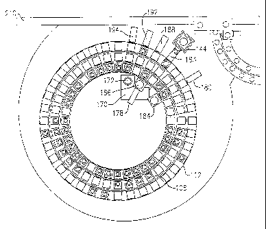
Referring to Figs. 3-12, an incubator 100 in accordance with a preferred
second embodiment of the invention includes a ring assembly 104 having a
pair of concentric rings; namely, a first or inner ring 108 and a second or
outer
ring 112. Each of the inner and outer rings 108, 112 include a plurality of
circumferentially spaced incubation positions.
According to this embodiment, the inner ring 108 is defined by a circular
platen consisting of an array of pairs of radially adjacent slide element
positions 116, 118, while the outer ring 112 includes a single circular array
of
slide element positions 122. A plurality of circumferential load stations are
therefore defined, each load station being made up of an inner slide element
position 116 and a middle or intermediate slide element position 118 each
provided on the inner ring 108, as well as an outer slide element position 122
provided on the outer ring 112. A total of thirty-six (36) slide element
positions
are provided for each ring 108, 112, though it should be readily apparent that
this parameter can easily be varied depending on the application.
Each of the inner and intermediate slide element positions 116, 118
defined by the inner ring 108 include a through opening 111 that permits read
access by a reflectometer or other device capable of detecting an optical
property of a test sample. The reflectometer 153, Fig. 7, is located beneath
the
inner ring 108 at an inner read station 150 as described below. According to
this specific embodiment, no openings are provided for any of the outer slide
element positions 122 of the outer ring 122, for reasons which will become
apparent below.
CA 02422741 2003-03-12
WO 03/006997 PCT/US02/20815
12
A cover 126 is provided for the ring assembly 104 as partially shown in
Fig. 3. The cover 126 provides thermal insulation to aid in temperature
control
of the interior of the incubator 100.
According to the present embodiment, the inner ring 108 and the outer
ring 112 are each independently driven about a common center axis of
rotation. As noted previously, the inner ring 108 is a single circular plate-
like
member which is driven by a belt drive 130, while the outer ring 112 is
rotated
onto a circular track 138, Fig. 9, using a gear drive. Each of the rings
108,112
are peripherally supported by a set of V-bearings 134, as partially shown in
Figs. 7 and 9, the incubator further including a hot plate 105 onto which each
ring 108, 112 is mounted. The hot plate includes, for example, circular track
138, Fig. 9. It should be pointed out that the specific driving mechanisms for
each of the rings 108, 112 of the herein described ring assembly 104 do not in
and of themselves form an essential part of the present invention. That is to
say, a number of different drive mechanisms could be substituted. Providing
independent driving capability of each of the inner and outer rings 108, 112,
however, is an important aspect of the invention, in that greater flexibility
in
the loading and shuttling transfer of slide elements 140, 144 into and between
each of the slide element positions 116, 118, 122 is provided. This loading
and
shuttling of slide elements into and within the incubator 100 will be
described
in greater detail below.
A single pair of read stations 150, 160, Figs. 4,7, are provided for the
incubator 100.- An inner read station 150, includes a reflectometer 153,
partially shown in Fig. 7, which is stationarily located beneath a
predetermined
circumferential position 154 relative to the inner ring 108 so as to be
aligned
with the array of rotatably movable inner slide element positions 116. The
inner read station 150 therefore permits the reading of either-rate chemistry
or
endpoint colorimetric slide elements 144 at the read location 154 through the
opening 111 of an aligned inner slide element position 116. Details relating
to the specific operation of the reflectometer 153 and the reading of test
elements in general are commonly known in the field, such as described in U.S.
CA 02422741 2009-09-25
13
Patent No. x,034,091,,
An outer read station 160 is also provided which is radially adjacent to
the outer ring 112. More specifically, the read station 160 is immediately
adjacent to each of the outer slide element positions 122, the read station
also
S being positioned at a predetermined circumferential position 164. As
detailed
below, an electrometer 163 (partially. shown in Fig. 4) is provided at the
outer
read station 160 which allows selective access to a potentiometric slide
element
140 after a predetermined incubation time when an element reaches the outer
read station 160.
In addition to the inner and outer read stations 150, 160 and as shown:
in Figs_ 3-6, 8 and 9, the herein described incubator 100 also includes a wash
module 170 located within the inner periphery of the inner ring 108 to permit
immuno-rate test capability. The wash module 170 includes an entrance slot
176 that is aligned with a slide pusher blade assembly 188, thereby permitting
a slide element 144 to be loaded into the wash station 170 directly from the
rotor assembly 104. The wash station 174 further includes a pivoting shuttle
assembly 175 which permits a loaded slide element 144 to be shuttled to a
wash position 172, as shown in Fig. 6, relative to a wash metering system (not
shown) which performs washing thereof. The washed slide element 144 can
then .be shuttled back to its input position such that the slide element can
be
transferred back into the inner ring 108 by means of an internal pusher blade
assembly 178.
Slide or evaporator caps 174, 179 some of which are partially depicted
in Figs. 7 and 8, are provided for all slide positions 116, 118, 122, within
the
incubator 100, thereby providing evaporation and thermal control for each
slide element 140, 144. Details relating to the general operation and function
of evaporator caps in a clinical analyzer incubator, including the raising of
same to load and unload same into and out of the housing through a cap
holder 177, are generally known in the field, as described for example in U.S.
Patent No. 5,034,191, to Porte, and U.S. Patent No. 4,963,333 to Shaw, et al.
CA 02422741 2009-09-25
14
and therefore do not form an essential part of the claimed
invention. For reasons described below,
evaporator caps 179 used for potentiormetric slide elements 140 are provided
for each of the outer slide element positions 122 while evaporator caps 174
used for colorimetric slide' elements 144 are provided for each of the slide
element positions 116, 118 of the inner ring 108.
In order to effectively shuttle any of the slide elements 140, 144 both into
and within the herein described incubator 100, a series of slide element
transferring devices are provided.
According to this specific embodiment, and as shown in Figs. 3, 5-7, and
10-12, a total of five slide transferring devices 180; 183, 188, 192, 194 are
provided in relation to a metering station 196.
Though shown only pictorially in Figs. 10-12, one slide transferring
device 183 is located directly within the confines of a metering station 196
in
order to initially shuttle a metered slide element, either a potentiometric or
colorimetric slide element 140, 144, into the incubator rotor assembly 104
from
a slide cartridge. The slide transferring device 183 operates in a manner
which
is commonly known, preferably using a reciprocating pusher blade.
The metering station 196 includes a metering head 198 which is
disposed along the length of a metering rail 210, Figs. 10-12. A metering
mechanism partially shown pictorially in. Figs. 10-12 permits a patient sample
to be delivered along the metering rail 210 froma. sample container (not
shown)
using a proboscis and a disposable metering tip (also not shown) so as to
dispense/meter sample onto a slide element 140, 144 provided from a slide
supply 204. According to this embodiment, the slide supply 204 retains a
plurality of vertically disposed sample cartridges (not shown) which are
loaded
into a carousel beneath the incubator 100. In a manner commonly known, the
slide elements are incremented one at a time to the metering head 198 and are
then shuttled into the outer ring 112 of the incubator 100. A series of bar
code
readers 206 are disposed in relation to the. slide supply 204 in order to
properly
identify the slide elements that are loaded into the incubator 100.
CA 02422741 2003-03-12
WO 03/006997 PCT/US02/20815
Three (3) of the remaining slide transferring devices 180, 192, 194 are
disposed adjacently to the metering station 196 to radially transfer slide
elements 140, 144 which have been loaded into the outer ring 112. More
particularly, the slide transferring devices 180, 192, and 194 are utilized to
transfer non-potentiometric slide elements 144 (either rate chemistry or
5 endpoint) to either the intermediate or inner slide element positions of the
inner ring 108 or to the wash station 170. The remaining slide transferring
device 180 is disposed on the opposite side of the metering station 196
adjacent to the read station 154. This specific transferring device 180 is
preferably adjacent to the inner read station 150 and is used to shuttle
10 colorimetric (e.g., rate) slide elements 144 to an inner eject slot 184
following
a final read thereof in order to dispose of the slide elements which are no
longer
needed and further to create an empty slide element position 116 in the inner
ring 108.
For purposes of this embodiment, three of the slide transferring devices
15 180, 192, 194 include a reciprocating pusher blade 200 having an
independent
drive mechanism. The pusher blade 200 has a length dimension which permits
the end of the blade to engage an edge of a slide element 140, 144 and
transfer
the slide element into either one of the designated slide positions of the
inner
and outer rings 108, 112. The slide transferring device 188 also includes a
reciprocating pusher blade 202 which is longer than the other pusher blades
200, this device being radially aligned with the entrance slot 176 of the wash
station 174.
All of the sample elements, whether potentiometric 140 or colorimetric
144 in type, are initially loaded into the outer ring 112 using the slide
transferring device 183, Figs. 10-12, located in the metering station 196. As
intended herein by the present embodiment, the outer slide positions 122
provide an incubation area for potentiometric slide elements 140, as well as
certain colorimetric slide elements 144, such as those requiring endpoint
testing which requires only a single read be performed at the inner read
station
150 following a predetermined incubation interval (e.g., approximately 5
CA 02422741 2003-03-12
WO 03/006997 PCT/US02/20815
16
minutes). Other colorimetric slide elements 144, such as those requiring rate
chemistries, require a number of reads to be taken by the reflectometer and
are
preferably shuttled to the inner slide element positions by one of the pusher
blade devices 192, 194 after the slide elements 144 have been loaded into the
outer ring 112.
In a preferred method of operation and referring to Figs. 4-12, the
incubator 100 of the present embodiment operates in the following manner.
According to this particular embodiment, all spotted (metered) slide
elements 140, 144 are initially loaded into the outer ring 112 of the rotor
assembly 104 using the slide transferring device 183. Because the outer read
station 160 is disposed in relation to the outer ring 112, potentiometric
slide
elements 140 are not transferred out of the outer ring 112 at any time. These
slide elements 140 are therefore maintained in the outer ring 112 during the
entire incubation process and are not shuttled to either of the interior slide
positions 116, 118.
The gear drive mechanism drives the outer ring 112 incrementally,
meaning that the outer ring is advanced one slide position per increment. The
inner ring 108, on the other hand, is driven by drive belt 130 at an N+ 1
increment in which N = one revolution of the ring, thereby incrementing the
inner ring with respect to the outer ring 112 per predetermined movement
thereof.
This provides a unique. and highly efficient means for loading and
advancing slides into and within the incubator. That is, the outer ring 112
can
be incremented or indexed by one position at a predetermined interval (e.g.
approximately 4.5 seconds). The independently driven inner ring 108 can be
driven one full revolution plus one position (N + 1) over twice the
predetermined
time interval (approximately 9 seconds) of the outer ring 112. Each of the
outer
and inner rings 112, 108 can be synchronized at the stopping position.
Therefore, the outer ring 112 will have advanced two positions while the inner
ring will have advanced one position. For example, the above synchronization
CA 02422741 2003-03-12
WO 03/006997 PCT/US02/20815
17
When the inner ring 108 stops, up to two slide elements can then be
loaded from the outer ring 112 into the inner ring 108 using blades 192, 194.
According to a specific protocol, blade 194 will move a slide element from the
outer slide element position 122 to a middle slide position 118 while blade
192
will move a slide element from the outer slide element position 122 to the
innermost slide position 116. This using of tandem loading technique thereby
maximizes the number of slides which can be processed by the incubator. It
should be further apparent that the duration of the time intervals can be
suitably varied.
In use and following a predetermined incubation interval, the
potentiometric slide element 140 is tested at the outer read station 160 by
the
electrometer 163 in a conventionally known manner as the potentiometric slide
element passes the outer read position 164. Following the read, the
potentiometric slide element 140 is no longer required according to this
embodiment. Therefore, the slide element 140 subsequently passes above an
outer dump station 148, shown in Fig. 9, which is provided as a slotted
portion
of the circular track 138 adjacent the read station 160. As the outer ring 112
rotates in a counterclockwise direction according to the drawings, the slotted
portion is exposed allowing the read slide element 140 to drop into the dump
station 148.
On the other hand, all reflectometer reads are taken at the read station
150 which is located in alignment with the inner slide element positions 116
as they rotate over the reflectometer 153, Fig. 7. It is desired to get rate
chemistry slide elements to the inner ring 108 as soon as possible using one
of the slide element transferring devices 192, 194. The endpoint slide
elements
are shuttled using either of the slide element transferring devices 192, 194
to
an intermediate slide element position 118 and subsequently to an inner slide
element position 116 for reading and subsequent disposal through either eject
slot 184 using the pusher blade 200 of the slide transferring device 180 or an
adjacent eject slot 186, Fig. 8, disposed adjacently to the entrance slot 176
of
CA 02422741 2003-03-12
WO 03/006997 PCT/US02/20815
18
wash station 170 using pusher blade 202 of slide transferring device 188
following a reflectometer read at station 150, Fig. 4.
In the case of an immuno-wash requirement, a spotted colorimetric slide
element 144 is initially loaded into the outer ring 112 at the metering
station
196. As the outer ring 112 advances incrementally by means of the gear drive
mechanism, the slide element 144 is engaged by the pusher blade 202 of slide
element transferring device 188 which pushes a slide element which is located
in an inner slide element position 116 directly into the wash station 172
through the entrance slot 1.76 for immuno-rate wash. Preferably, the outer
ring load stations 122 are raised in relation to those of the inner ring 108
permitting the pusher blade 202 to pass beneath a potentiometric element 140,
as shown more closely in Fig. 8, without engaging therewith.
As previously noted and during wash, the slide element 144 is
transferred to the wash station 170 through the entrance slot 176 by means
of the pusher blade 202 top an input position. The slide element 144 is then
transferred by means of the pivotal shuttle 175 to a wash station and washed
before the slide element is pivoted back to the input position and is
reinserted
back into the inner ring 108 through the slot 176 using the pusher blade 178.
It should be noted that in order to perform this particular step, an empty
inner
slide element position 116 would have to be reserved in the inner ring 108
prior
to reinsertion of the washed slide element 144.
CA 02422741 2003-03-12
WO 03/006997 PCT/US02/20815
19
PARTS LIST FOR FIGS. 1-12
incubator
12 linear array
13 row
14 load stations
5 15 slot or receiving area
16 row
17 slot or receiving area
18 slide element
18A slide element
10 18B slide element
19 openings
first direction
23 slide element transferring device
slide element transferring device
15 30 read station
31 slide supply
32 metering station
33 staging position
34 second direction
20 38 dump station
50 incubator assembly
54 rotor assembly
58 rotor assembly
100 incubator
25 104 rotor assembly
105 hot plate
108 inner ring
112 outer ring
116 inner slide element position
118 intermediate slide element position
122 outer slide element position
126 cover
130 drive belt
134 V-bearings
138 track
140 potentiometric slide element
142 dump station
144 colorimetric slide element
148 slotted portion
150= inner read station
153 reflectometer
154. read location
160 outer read station
163 electrometer
CA 02422741 2003-03-12
WO 03/006997 PCT/US02/20815
164 read position
170 wash station
172 wash position
174 evaporator caps
175 shuttle assembly
5 176 entrance slot
177 holder for evaporator caps
178 pusher blade
179 evaporator caps
180 slide transferring device
10 18.3 'slide transferring device
184 eject slot
186 eject slot
188 slide transferring device
192 slide transferring device
15 194 slide transferring device
196 metering station
198 metering head
200 reciprocating pusher blade
202 reciprocating pusher blade
20 204 slide element supply
206 bar code readers
210 metering rail
Though the preceding has been described in terms of certain specific
embodiments, it will be apparent that certain variations and modifications are
possible which still embody the inventive concepts of the present invention.
For example, any of the read stations can be otherwise disposed. For example,
the reflectometer can. be located in a read position which is fixedly held
relative
to the outer incubator ring. In this version, the'electrometer can be located
within the incubator; that is, radially inward of the inner ring. The
potentiometric slide element 140 can be selectively picked from an outer slide
element position 122 by means of a conventionally known picker assembly (not
shown) and transferred to a read station (not shown) to then be read by the
electrometer. The potentiometric slide element 140 following the read
operation
can'then be shuttled by known means to an external dump station (not shown)
for disposal thereof.