Language selection

Search

Patent 2422943 Summary

Third-party information liability

Some of the information on this Web page has been provided by external sources. The Government of Canada is not responsible for the accuracy, reliability or currency of the information supplied by external sources. Users wishing to rely upon this information should consult directly with the source of the information. Content provided by external sources is not subject to official languages, privacy and accessibility requirements.

Claims and Abstract availability

Any discrepancies in the text and image of the Claims and Abstract are due to differing posting times. Text of the Claims and Abstract are posted:

  • At the time the application is open to public inspection;
  • At the time of issue of the patent (grant).
(12) Patent Application: (11) CA 2422943
(54) English Title: METHOD AND DEVICE FOR THE PRODUCTION OF PURE STEAM
(54) French Title: PROCEDE ET APPAREIL DE PRODUCTION DE VAPEUR PURE
Status: Deemed Abandoned and Beyond the Period of Reinstatement - Pending Response to Notice of Disregarded Communication
Bibliographic Data
(51) International Patent Classification (IPC):
  • B01D 1/22 (2006.01)
  • B01D 1/06 (2006.01)
  • B01D 45/16 (2006.01)
(72) Inventors :
  • SALMISUO, MAURI (Finland)
(73) Owners :
  • STERIS EUROPE INC. SUOMEN SIVULIIKE
(71) Applicants :
  • STERIS EUROPE INC. SUOMEN SIVULIIKE (Finland)
(74) Agent: OSLER, HOSKIN & HARCOURT LLP
(74) Associate agent:
(45) Issued:
(86) PCT Filing Date: 2001-09-19
(87) Open to Public Inspection: 2002-03-28
Examination requested: 2006-08-29
Availability of licence: N/A
Dedicated to the Public: N/A
(25) Language of filing: English

Patent Cooperation Treaty (PCT): Yes
(86) PCT Filing Number: PCT/FI2001/000810
(87) International Publication Number: WO 2002024299
(85) National Entry: 2003-03-21

(30) Application Priority Data:
Application No. Country/Territory Date
20002104 (Finland) 2000-09-25

Abstracts

English Abstract


A method and a device for the production of pure steam, wherein steam produced
in downflow evaporation tubes is carried upwards in a spiraling path. In the
outer wall of the spiral path, openings are provided for capturing droplets
carried to the wall by centrifugal force. A radial flow through the openings
is generated as steam condenses on a cooled surface outside the openings.
Impurities are enriched in the water phase that forms on the cooled surface,
and the water phase flows downwards by gravity to form a pool of reject water,
a flow of which is constantly removed from the process. Pure steam is
withdrawn from above the spiral path.


French Abstract

L'invention concerne un procédé et un dispositif de production de vapeur pure, dans lequel la vapeur produite dans des tubes d'évaporation à courant descendant est entraînée vers le haut dans un chemin en spirale. La paroi extérieure du chemin en spirale comporte des ouvertures qui attirent les gouttes amenées sur la paroi sous l'action de la force centrifuge. Un écoulement radial traversant les ouvertures et transformé en vapeur se condense sur une surface refroidie à l'extérieure des ouvertures. La phase aqueuse qui se forme sur la surface refroidie est riche en impuretés. Elle s'écoule vers le bas sous l'action de la gravité pour former une masse d'eau de rejet dont un courant est régulièrement éliminé du processus. La vapeur pure obtenue est extraite en haut du chemin en spirale.

Claims

Note: Claims are shown in the official language in which they were submitted.

5
Claims
1. A method for purifying an evaporation product to produce pure steam,
wherein the
evaporation product is set in a spiraling rotational motion to separate
droplets by centrifu-
gal force, characterized by the transport of droplets and impurities carried
to the periphery
of the spiraling path through at least one opening provided in the outer
surface of said path,
and the collection of the droplets and impurities on an actively cooled
surface outside said
openings.
2. The method according to claim 1, characterized by the evaporation product
being pro-
duced in a falling-film evaporator.
3. The method according to claim 1, characterized by the temperature of the
cooled sur-
face being controlled by means of water used as feed water.
4. A device for the purification of an evaporation product to produce pure
steam, having a
pressure vessel shell and a rising space for the evaporation product and fins
in said rising
space forming a spiral path, characterized by at least one opening in the
outer surface of
the spiral path and a temperature-regulated surface outside said openings.
5. The device according to claim 3, characterized by the openings being
vertical slits.
6. The device according to claim 3 or 4, characterized by at least one detail
within the
pressure vessel shell being detachable.
7. The device according to any claim 3 - 5, characterized by at least one
detail within the
pressure vessel shell being made from a corrosive resistant material different
from that of
the pressure vessel shell.

Description

Note: Descriptions are shown in the official language in which they were submitted.


CA 02422943 2003-03-21
WO 02/24299 PCT/FI01/00810
1
METHOD AND DEVICE FOR THE PRODUCTION OF PURE STEAM
Field of the invention
The invention relates to the production of highly pure steam for special
purposes. Particu
larly, the invention relates to the production of pure steam using a falling-
film evaporator
and rising channels for separating water droplets and impurities.
Background of the invention
Highly purified steam is required for various medical purposes, such as
production of
pharmaceuticals, demanding sterilization applications and production of water
for injec
tion. A method and device for production of such steam are disclosed in US
patent
3,875,017. A falling film evaporator as disclosed therein comprises a vertical
bundle of
evaporation tubes enclosed into a heating jacket, which in turn is enclosed by
an outer shell
so that an annular space is formed between the heating jacket and the outer
shell. Water fed
into the evaporating tubes at their upper end flows down the inner surface of
the tubes,
thereby evaporating and forming steam, which emerges at the lower ends of the
tube bun-
dle. The flow of steam makes a 180° turn and flows upwards in the
space, between the
heating jacket and the outer shell. Fins forming a spiral path are attached to
the outer sur-
face of the heating jacket, leaving a narrow gap between their edges and the
inner surface
of the shell. The steam flowing upwards is forced into a spiraling path,
whereby water
droplets in the evaporation product are driven towards the outer shell by
centrifugal force.
The droplets adhere to the outer shell wall and form a film of water flowing
downwards
and finally forming a pool of liquid at the bottom of the device. From there,
a stream of
water proportional to the amount of pure steam produced is withdrawn as a
reject stream.
As the water phase in the evaporation product tends to be rich in impurities,
these are en-
riched into the reject stream. From above the spiral path, pure steam is led
to the consump-
tion points or to a condenser for producing highly pure water.
A variation of the device is disclosed in US patent 5,983,842. The evaporation
product
emerging from the lower ends of the tube bundle is brought into a circular
motion by baffle
fins at the bottom of the device, and the rising space narrows towards the
top. The spiral
path is arranged into the top of the rising space and it is closed, i.e. the
fins reach the inner
surface of the outer shell. No downwards-flowing reject phase is formed, but
the droplets
accelerate and are collected into an annular channel above the spiral path. A
separate tube
returns the resulting water phase to the bottom of the device.

CA 02422943 2003-03-21
WO 02/24299 PCT/FI01/00810
2
Summary of the invention
An improved method and device have been invented for enhancing the separation
of water
droplets and impurities in the rising channel of a falling film evaporator for
production of
highly pure steam. A further object of the invention is a system for the
production and dis
tribution of pure steam, the system comprising the improved device.
The device according to the present invention is used together with a vertical
tube bundle
with a heating jacket, i.e. a conventional type of falling film evaporator.
The evaporation
product emerges from the lower end ofthe tube bundle.
According to the invention, the device for separating water droplets and
impurities from
the evaporation product comprises a length of downpipe through which the
evaporation
products initially flows before making a 180 ° turn and entering a
rising channel between
the outer surface of the downpipe and the inner surface of an intermediate
shell. The
downpipe may be initially tapered, forming a funnel.
Spiral fins adapted in the upper part of the rising channel set the
evaporation product in an
upwardly spiraling, circular motion. According to the present invention, the
intermediate
shell is provided with at least one opening or outlet slit, allowing droplets
carried by cen
trifugal force to the periphery of the spiral path to leave. Outside the
openings, a cooled
surface in the outer shell ensures, that condensation of steam takes place.
Steam condensing on the inner surface of the outer shell causes a radial
outward stream
carrying steam, water droplets and impurities to the said inner surface. A
water film is
formed which flows down said surface in the space between the outer and
intermediate
shells. A pool of water is formed on the bottom of the unit, submerging the
lower edge of
the intermediate shell. A controlled stream of reject water is withdrawn from
the pool. The
pure, dry steam leaving the upper end of the spiral path exits the device.
The invention enables the use of detachable inner parts in the steam
generator, which pro-
vides for easy maintenance and cleaning, as the whole of the apparatus need
not be pres-
sure vessel certified.
Brief description of the drawings
The invention is disclosed in detail below with reference to the accompanying
drawings,
wherein
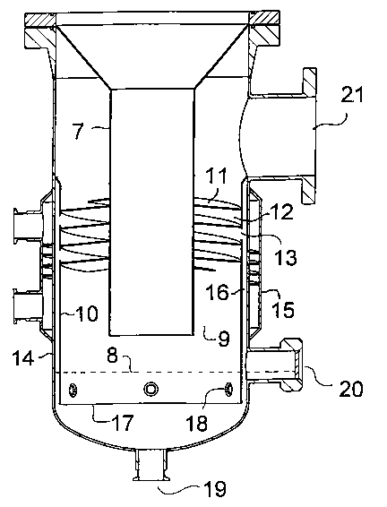
Figure 1 shows a steam generator comprising a falling film evaporator provided
with a
separator unit according to the present invention,
Figure 2 shows details of a separator unit according to the present invention,

CA 02422943 2003-03-21
WO 02/24299 PCT/FI01/00810
3
Figure 3 is a top view section of the unit of Fig. 2, and
Figure 4 shows a system for the production of pure steam, which system
includes the de-
vice of Figure 2.
Disclosure of the invention
Figure 1 shows a shell-and-tube heat exchanger arranged in a vertical position
to form a
falling film evaporator. Evaporation tubes 1 are enclosed in a jacket 2,
through which a
heating medium is conducted via in- and outlets 4 and 5. Feed water enters the
upper ends
of the evaporation tubes through inlet 6. At the lower end of the evaporator,
a separating
device according to the invention is connected.
The construction of the separating device is shown in Figure 2. The
evaporation product
enters downpipe 7. In the embodiment shown, the upper end of the downpipe is
shaped as
a funnel in order to maintain the same outer diameter in the separator as in
the evaporator.
The evaporation product emerges from the lower end of the downpipe, encounters
the wa-
ter surface 8 on the bottom of the device, and turns 180 ° to enter the
annular rising channel
9 between the downpipe and intermediate shell 10. Spiral fins 11 form a spiral
path 12 for
the evaporation product.
The spiral movement of the evaporation product causes centrifugal force which
force water
droplets in the product to the periphery of path 12. Foreign matter present in
the evapora-
tion product may act as nuclei for condensation, and this phenomenon thus
enhances the
transport of this matter to the periphery of the spiral path. Pure, dry steam
leaves spiral
path 12 and exits the device at connection 21.
At least one opening 13 is provided the intermediate shell 10 to allow
droplets to enter
space 16 between the intermediate shell and outer shell 14. Outer shell 14 is
provided with
a temperature control jacket 15. As this jacket is used to cool the inner
surface of shell 14,
steam in space 16 condense on said inner surface and form a descending water
film. The
condensation ensures, that no backflow occurs into spiral path 12 through
openings 13. A
suitable number of openings 13 of an appropriate shape may be provided.
Droplets and
impurities driven to the inner wall of shell 10 by centrifugal force pass
through the open-
ings, and are carried to the cooled inner wall of outer shell 14 by the radial
outward stream
caused by condensation of steam.
The openings may be designed as vertical slits in the outer periphery of the
spiral path, i.e.
in shell 10. One or more slits running in parallel to the spiral fins is also
possible, as well

CA 02422943 2003-03-21
WO 02/24299 PCT/FI01/00810
4
as circular, oval or other shapes of openings, possible arranged with edges
enhancing the
capture of droplets in circular motion along the spiral path.
The surface of the pool of water formed from condensate and droplets is kept
above lower
edge 17 of intermediate shell 10; thus flow of evaporation product is possible
only along
the route described. Spacer indents 18 may be provided to center the lower end
of the in
termediate shell. A reject flow rich in impurities is withdrawn at 19. A sight
glass 20 may
be provided to monitor the water level.
Figure 3 shows a top view of the unit of Figure 2, with the top cut off at the
level of the
temperature control jacket. The large arrows indicate the circular movement of
the evapo
ration product in the spiral path. Openings 13 are shown with baffles 16 to
enhance the
capture of droplets and impurities carried to the periphery of the path, as
shown by the
small arrows
Preferably, the temperature of outer shell 14 is be controlled to effect a
suitable rate of
condensation. To conserve energy, feed water can be used in jacket 15. By
means of this
temperature control, the amount of reject water formed can be controlled
according to Load
and purity requirements.
Figure 4 shows a system for the production of pure steam. To a falling film
evaporator 22,
feed water is provided by means of pump 23. The evaporator comprises a
separating unit
24 according to the present invention. Heating steam enters through valve 25,
while con-
densate leaves by connection 26 (tubing not shown). Pure steam leaves the
evaporator via
line 27 and control valve 28, and enters the distribution network which
includes pure steam
line valves 29 and pure steam traps 30. Reject water enriched in impurities
leaves separat-
ing unit 24 through line 31. Feed and return lines 32,33 for the temperature
control jacket
are provided.
In prior art devices, corrosion and the closed structure of the separator
units caused prob-
lems as the steam paths were not easily accessible The inner structure was
integrated with
the pressure vessel shell, and could not be altered without going through the
tedious proce-
dure involved with pressure vessel construction. In the disclosed device
according to the
invention, only the outer shell part must fulfil pressure vessel requirements.
Accordingly,
the inner parts andlor details thereof can be manufactured from any required,
corrosion-
proof material, and may be removed for cleaning and inspection. Such materials
include
fluorocarbon polymers, ceramic materials and special steels or other metals
which need not
be suited for being joined by welding to the pressure vessel shell. The inner
parts may also
be exchanged to suit different throughputs and purity requirements.

Representative Drawing
A single figure which represents the drawing illustrating the invention.
Administrative Status

2024-08-01:As part of the Next Generation Patents (NGP) transition, the Canadian Patents Database (CPD) now contains a more detailed Event History, which replicates the Event Log of our new back-office solution.

Please note that "Inactive:" events refers to events no longer in use in our new back-office solution.

For a clearer understanding of the status of the application/patent presented on this page, the site Disclaimer , as well as the definitions for Patent , Event History , Maintenance Fee  and Payment History  should be consulted.

Event History

Description Date
Inactive: Agents merged 2013-10-24
Application Not Reinstated by Deadline 2008-09-19
Time Limit for Reversal Expired 2008-09-19
Deemed Abandoned - Failure to Respond to Maintenance Fee Notice 2007-09-19
Amendment Received - Voluntary Amendment 2006-10-05
Letter Sent 2006-09-27
Request for Examination Received 2006-08-29
All Requirements for Examination Determined Compliant 2006-08-29
Request for Examination Requirements Determined Compliant 2006-08-29
Inactive: IPC from MCD 2006-03-12
Letter Sent 2003-07-29
Inactive: Single transfer 2003-06-10
Inactive: Courtesy letter - Evidence 2003-06-03
Inactive: Cover page published 2003-05-30
Inactive: Notice - National entry - No RFE 2003-05-28
Application Received - PCT 2003-04-16
National Entry Requirements Determined Compliant 2003-03-21
Application Published (Open to Public Inspection) 2002-03-28

Abandonment History

Abandonment Date Reason Reinstatement Date
2007-09-19

Maintenance Fee

The last payment was received on 2006-09-12

Note : If the full payment has not been received on or before the date indicated, a further fee may be required which may be one of the following

  • the reinstatement fee;
  • the late payment fee; or
  • additional fee to reverse deemed expiry.

Please refer to the CIPO Patent Fees web page to see all current fee amounts.

Fee History

Fee Type Anniversary Year Due Date Paid Date
Basic national fee - standard 2003-03-21
Registration of a document 2003-06-10
MF (application, 2nd anniv.) - standard 02 2003-09-19 2003-09-09
MF (application, 3rd anniv.) - standard 03 2004-09-20 2004-09-16
MF (application, 4th anniv.) - standard 04 2005-09-19 2005-09-02
Request for examination - standard 2006-08-29
MF (application, 5th anniv.) - standard 05 2006-09-19 2006-09-12
Owners on Record

Note: Records showing the ownership history in alphabetical order.

Current Owners on Record
STERIS EUROPE INC. SUOMEN SIVULIIKE
Past Owners on Record
MAURI SALMISUO
Past Owners that do not appear in the "Owners on Record" listing will appear in other documentation within the application.
Documents

To view selected files, please enter reCAPTCHA code :


To view images, click a link in the Document Description column. To download the documents, select one or more checkboxes in the first column and then click the "Download Selected in PDF format (Zip Archive)" or the "Download Selected as Single PDF" button.

List of published and non-published patent-specific documents on the CPD .

If you have any difficulty accessing content, you can call the Client Service Centre at 1-866-997-1936 or send them an e-mail at CIPO Client Service Centre.


Document
Description 
Date
(yyyy-mm-dd) 
Number of pages   Size of Image (KB) 
Description 2003-03-21 4 256
Representative drawing 2003-03-21 1 15
Drawings 2003-03-21 4 79
Claims 2003-03-21 1 38
Abstract 2003-03-21 2 62
Cover Page 2003-05-30 1 39
Reminder of maintenance fee due 2003-05-28 1 107
Notice of National Entry 2003-05-28 1 189
Courtesy - Certificate of registration (related document(s)) 2003-07-29 1 106
Reminder - Request for Examination 2006-05-23 1 116
Acknowledgement of Request for Examination 2006-09-27 1 176
Courtesy - Abandonment Letter (Maintenance Fee) 2007-11-14 1 173
PCT 2003-03-21 8 374
Correspondence 2003-05-28 1 25
Fees 2003-09-09 1 46
Fees 2004-09-16 1 46
Fees 2005-09-02 1 47
Fees 2006-09-12 1 48