Note: Descriptions are shown in the official language in which they were submitted.
CA 02423349 2003-03-20
WO 02/25225 PCT/USO1/29355
SPECIFICATION
TITLE:
"FLUID DISPENSERS"
FIELD OF THE INVENTION
The present invention generally relates to fluid dispensers, and more
specifically, the
present invention relates to fluid dispensers which accurately control the
amount of fluid dispensed.
The present invention also relates to methods of dispensing fluid in a
controlled manner. One
specific example of a fluid dispenser according to the present invention is a
paint colorant dispenser.
BACKGROUND OF THE INVENTION
Paints are made in a vast number of different colors and shades of colors.
Each specific
paint color has a specific formula of components to provide the desired color.
A paint formula
generally includes a relatively large amount of a base and smaller amounts of
one or more colorant
colors. Each colorant color is measuxed according to the formula and dispensed
from a bulk colorant
supply, added to the base, and then mixed to produce the desired paint color.
Existing colorant dispensers have been used in retail paint supply stores and
hardware
stores, for example. Existing colorant dispensing equipment has included
manual and automated
machines. Automated colorant dispensing equipment can include several bulk
colorant containers,
CA 02423349 2003-03-20
WO 02/25225 PCT/USO1/29355
in which each colorant container is connected to an inlet of a fluid pump. The
outlet of the fluid
pump is connected to a 3-way valve which has a dispense outlet connected to a
dispense nozzle and
a by-pass outlet connected to a recirculation fluid line. Either one motor may
drive all pumps or
several pumps may be driven by a single motor through a common drive mechanism
or each pump
may be driven by an individual motor. When an amount of colorant is dispensed,
the motor drives
the pumps and the 3-way valve for the particular colorant is opened to allow
the colorant to be
dispensed through the nozzle. The time period that the valve remains open
determines the amount
of colorant dispensed. The other 3-way valves, which are all being
simultaneously driven by the
motor, are in a by-pass mode so that the colorant recirculates back into its
container rather than being
undesirably dispensed.
However, existing colorant dispensing equipment can be improved. The colorant
dispensing equipment utilizes a 3-way valve for each colorant container, which
increases the
equipment costs and manufacturing costs. Also, the plurality of 3-way valves
tend to be a significant
source of maintenance and service problems. Furthermore, the accuracy of the
amount of colorant
dispensed using the pump and valve arrangement can be improved. Also, a by-
pass colorant flow
path is needed because the single motor simultaneously operates all of the
pumps. It is desired to
more accurately control the amount of colorant dispensed so that the resulting
paint color for any
particular formula is consistent. Greater accuracy and control over the
colorant dispensing process
provides greater consistency in paint color for any given formula.
One paint colorant dispenser according to the present invention utilizes a
nutating pump
and a computer control system to control the pump. Nutating pumps have a
piston which is
positioned inside of a housing having a fluid inlet and a fluid outlet. The
piston simultaneously
slides axially and rotates inside of the housing. Existing nutating pumps have
been operated by
2
CA 02423349 2003-03-20
WO 02/25225 PCT/USO1/29355
rotating the piston through a full 360° rotation and corresponding
linear travel of the piston. Such
piston operation results in a specific amount of fluid pumped by the nutating
pump with each
revolution. Accordingly, the amount of fluid pumped for any given nutating
pump is limited to
multiples of the specific volume. If a smaller volume of fluid is desired,
then a smaller sized
nutating pump is used or manual calibration adjustments are made to the pump.
For example, in
paint coloranting a minimum dispense can be about 1/256th of a fluid ounce. At
such a small
dispense, the motor would have had to run at excessive speeds to dispense
larger volumes of colorant
(multiple full revolutions) in an appropriate time period. In order to
minimize the dispense motor
speed, a partial-revolution dispense for a larger capacity nutating pump would
be advantageous.
However, using a partial revolution to accurately dispense fluid is difficult
due to the non-linear
output of the nutating pump dispense profile vs. angle of rotation.
Accordingly, needs exist to
automatically control and vary the volume amount of fluid pumped by nutating
pumps.
SUMMARY OF THE INVENTION
The present invention provides new colorant dispensers which accurately,
consistently, and
effectively dispense fluid. The invention is described as embodied in a paint
colorant dispenser;
however, the invention can be utilized to dispense any desired fluid. For
example, the fluid
dispensers can be used to dispense pharmaceuticals, cosmetics, inks, and other
fluids at controlled
volumes.
The paint colorant dispenser has a computer control system which operates a
stepper motor
or other incrementally controlled drive that drives a valueless pump, such as
a nutating pump. Paint
color formulas are stored in the computer control system and selected by an
operator to mix a desired
color of paint. The nutating pump pumps colorant from a bulk container to a
dispense nozzle based
3
CA 02423349 2003-03-20
WO 02/25225 PCT/USO1/29355
on signals sent by the computer control system according to the paint color
formula. The computer
control system operates the stepper motor and the nutating pump such that the
pump piston rotates
less than a full 360° revolution for each step of the stepper motor.
For example, 400 steps may be
required for one full 360° revolution. The stepper motor and the
nutating pump are rotated through
a desired number of steps to dispense a desired amount of fluid.
The fluid dispense system having the nutating pump and computer control system
accurately dispenses both large and small quantities of fluid. The computer
control system controls
the stepper motor and nutating pump to dispense a predetermined amount of
fluid by dividing one
full 360 pump piston revolution into several partial dispenses or segments.
S -:f.
The nutating pump of the present invention can be adjustable. For example, the
angle
between the axis of the nutating pump piston and the axis of the stepper motor
shaft can be adjusted
by an actuator. The computer control system sends signals to the actuator to
operate the actuator
which positions the nutating pump piston at a desired angle. The automated
nutating pump angle
adjustment effectively adjusts the pump fluid output through computer control.
Another nutating pump adjustment also provides for changing the pump fluid
output. In
this adjustment, the distance that a spherical bearing is off set from the
stepper motor shaft can be
varied. The bearing off set adjustment alters the fluid output of the nutating
pump, and can be used
to calibrate the pump, for example.
Various advantages of the present invention can become apparent upon reading
this
disclosure including the appended claims with reference to the accompanying
drawings. The
advantages may be desired, but not necessarily required to practice the
present invention.
4
CA 02423349 2003-03-20
WO 02/25225 PCT/USO1/29355
BRIEF DESCRIPTION OF THE DRAWINGS
Figure 1 is a perspective, partial cut-away view of a fluid dispense system
according to the
principles of the present invention.
Figure 2 is an enlarged perspective view of a portion of the fluid dispense
system of Fig.
1.
Figure 3 is a perspective, exploded view of a nutating pump of Fig. 2.
Figure 4 is a perspective view of a position sensor according to the present
invention.
Figure 5 is graph of a dispense profile for a nutating pump according to the
present
invention.
Figure 6 is a front elevational view of a piston of the nutating pump of Fig.
3.
Figure 7 is a top plan view of the piston of Fig. 6.
Figure 8 is a left side view of the piston of Fig. 7.
Figure 9 is a right side view of the piston of Fig. 7.
Figure 10 is a front elevational, partial cross-sectional view of a piston
housing according
to the present invention.
Figure 11 is a top plan view of the piston housing of Fig. 10.
Figure 12 is a left side view of the piston housing of Fig. 10.
Figure 13 is a front elevational, partial cross-sectional view of another
piston housing
according to the present invention.
Figure 14 is a top plan view of the piston housing of Fig. 13.
Figure 15 is a left side view of the piston housing of Fig. 13.
Figure 16 is an elevational view of an adjustable nutating pump according to
the present
invention.
CA 02423349 2003-03-20
WO 02/25225 PCT/USO1/29355
Figure 17 is an enlarged, partial perspective view of a piston driver of Fig.
16.
DETAILED DESCRIPTION OF PRESENTLY PREFERRED EMBODIMENTS
Although the present invention can be made in many different forms, the
presently
preferred embodiments are described in this disclosure and shown in the
attached drawings. This
disclosure exemplifies the principles of the present invention and does not
limit the broad aspects
of the invention only to the illustrated embodiments.
A fluid dispense system 10 according to the present invention is shown in Fig.
1. The fluid
dispense system 10 dispenses a variety of paint colorant colorants from
several colorant canisters
12 which hold bulk colorant colorants. The fluid dispense system 10 has a
computer control system
14 which stores the paint color formulas and operatively controls the fluid
dispense system 10 to
dispense the correct colorants and amounts of the colorants into a base paint.
Once the proper
colorants have been dispensed into the base paint, the coloranted paint is
thoroughly mixed to
produce the desired colored paint.
Refernng to Figs. 1 and 2, each colorant canister 12 is fluidly connected to
an inlet to a
fluid pump 16 by a tube 18. The embodiment of the present invention shown in
Figs. 1 and 2
includes a nutating pump as the fluid pump 16; however, other fluid pumps are
contemplated by the
invention. An outlet from the fluid pump 16 is fluidly connected to an inlet
20 to a dispense nozzle
22 by a delivery tube 24. A stepper motor 26 is linked to and drives the fluid
pump 16. Although
a stepper motor is described, those skilled in the art will recognize that
other fine control drives may
be utalized. The stepper motor 26 is operatively/electrically connected to and
controlled by the
computer control system 14. The nutating pump 16 functions both as a fluid
pump and as a valve,
6
CA 02423349 2003-03-20
WO 02/25225 PCT/USO1/29355
and thus, a separate valve is not required to dispense the colorants. In other
words, the fluid dispense
system 10 is a valueless system from the colorant canister 12 to the dispense
nozzle 22.
An agitation motor 28 is connected to and drives an agitator 30 positioned
inside of the
colorant canister 12. The computer control system 14 operates the agitation
motor 28 to drive the
agitator 30 and maintain a consistent mix of the colorant colorant in the
colorant canister 12.
The dispense nozzle 22 has a plurality of inlets 20 in which each dispense
nozzle inlet 20
is provided for a separate colorant colorant. The dispense nozzle 22 has an
outlet 32 which points
downward and is above a roller shelf 34. An open can of base paint is placed
on the roller shelf 34
underneath the dispense nozzle outlet 32 for dispensing the colorant colorants
into the base paint.
The nutating pump 16 is shown in greater detail in Fig. 3. A piston 34 axially
reciprocates
and rotates inside of a liner 36. The liner 36 is contained within a housing
38 by a nut 40 and a seal
42. The piston 34 has a pin 44 engaged with a spherical bearing 46 which is
held by a rotatable
sleeve 48. The sleeve 48 is mounted to and rotatably driven by a shaft of the
stepper motor 26. The
stepper motor 26 and these components are mounted to a bracket 50.
The sleeve 48 has a sensor proj action 52 which allows for determination of
the rotational
position of the stepper motor 26 and the piston 34. ,As one alternative to the
sensor projection 52,
a sensor wheel 54 can be provided on the shaft 56 of the stepper motor 26. A
home sensor 58 is
positioned such that it can sense the position of the sensor wheel 54. For
example, the home sensor
58 can be a photo-sensor which has a light beam that is interrupted by the
sensor wheel 54 depending
on the angular position of the sensor wheel 54. The home sensor 58 is
electronically connected to
the computer control system 14 of the fluid dispense system 10 by a wire 60.
The sensor wheel 54
and the home sensor 58 combine to form a position sensor 62 which provides a
signal to the
7
CA 02423349 2003-03-20
WO 02/25225 PCT/USO1/29355
computer control system 14 indicative of the rotational position of the
stepper motor 26 and the
piston 34 of the nutating pump 16. It will be understood by those in the art
that many different types
of position sensors may be employed for determining and controlling stepper
motor position, for
example, the sensor 58 could be a ball effect switch.
The embodiment of the position sensor 62 shown in Fig. 4 senses the angular
position of
the shaft 56 each time the leading edge 64 of the sensor wheel 54 rotates and
breaks the light beam.
The position of the leading edge 64 breaking the light beam and tripping the
home sensor 58 defines
the "homy position" of the nutating pump 16, i.e. the home position of the
piston 34 in the liner 36.
The home position of the nutating pump 16 is a defined axial and rotational
position of the piston
34 in the liner 36. When the light beam is broken by the leading edge 64 of
the sensor wheel 54, the
home sensor 58 sends a signal indicative of the home position to the computer
control system 14.
The computer control system 14 receives and interprets the signal. In this
manner the computer
control system 14 determines when the nutating pump 16 is in the home
position. The home position
can be set at any desired position of the nutating pump 16; however, a
convenient position may be
top dead center or bottom dead center of the piston 34 in the liner 36.
The computer control system 14 can determine the position of the nutating pump
16 (axial
and rotational positions of the piston 34) at any time, e.g. continuously
tracks the nutating pump
position. The position of the nutating pump 16 is determined by starting with
the home position -
which is a known position - and adding the amount of rotation imparted on the
piston 34 by the
stepper motor 26. As the stepper motor 26 rotates the sensor wheel 54, the
next time the leading
edge 64 trips the home sensor 58 the computer control system resets the
computer stored position
of the nutating pump 16 at the home position.
CA 02423349 2003-03-20
WO 02/25225 PCT/USO1/29355
The home sensor 58 in the embodiment shown in Fig. 4 is a single position
sensor, i.e. it
only senses the home position. However, other position sensors could be
utilized which can sense
various positions of the shaft 56 or the nutating pump 16.
Stepper motors are well known and can be precisely controlled. Thus, the
computer
control system 14 can very accurately determine, track, and control the
positions of the nutating
pump 16. The nutating pump 16 is a highly accurate and consistent fluid pump.
Accordingly, the
computer control system 14, the stepper motor 26, and the nutating pump 16
accurately and
consistently pump a precise amount of colorant colorant from a given colorant
canister 12.
Operation of the nutating pump 16 will now be described assuming that the home
position
is defined as the piston 34 being slid the furthest distance into the liner 36
(top dead center) and the
pump chamber inside the liner 36 is "empty" of colorant. The computer control
system 14 sends a
signal to the stepper motor 26 to rotate 180° (bottom dead center)
which rotates the piston 34 180°
and fills the pump chamber inside the liner 36 with colorant through a pump
inlet 66. Colorant is
dispensed by the computer control system 14 sending another signal to the
stepper motor 26 to rotate
through a predetermined number of steps. The piston 34 rotates and slides into
the liner 36 and
colorant is pumped out of a pump outlet 68 and to the dispense nozzle 22.
The amount of colorant that is dispensed depends on the number of steps
rotated by the
stepper motor 26 and the corresponding movement of the piston 34 in the
nutating pump 16. The
nutating pump 16 has a non-linear output. The output of one revolution can be
graphed as one-half
of a sinusoidal pattern of displacement per step of the stepper motor, and as
a function of the
rotational position.
For example, the curve in Fig. 5 represents the dispense profile of the
nutating pump 16
versus angle of rotation of the associated stepper motor shaft 56 through
180° revolution of dispense.
9
CA 02423349 2003-03-20
WO 02/25225 PCT/USO1/29355
The area under the curve is broken into eight approximately equal segments in
the Fig: 5 graph
which represent equal amounts of fluid dispense. The area under the curve
could be broken into
other segments, as desired. By keeping track of angle rotation of the stepper
motor 16 with the
position sensor 62 and the computer control system 16, the rotation of the
motor shaft 56 can be
stopped at a point that will result in an accurate fraction (e.g., 1/8th) of
the full-rotation dispense of
the attached nutating pump 16.
In a preferred embodiment, the stepper motor 26 is used for the motor that
drives the
nutating pump 16. Stepper motors have their full rotation broken into a
plurality of discreet
segments, called steps. In preferred embodiments stepper motors 26 with 200
steps and 400 steps
can be used. Additionally, electronic control devices can break the steps into
smaller, partial steps
by careful control of the motor windings (a process known as half stepping, or
also microstepping).
In this way, within appropriate torque limits, the rotation of the stepper
motor can be accurately
determined without feedback by keeping track of how far the motor has been
driven around its
rotation.
In order to accurately synchronize the motor shaft 56 position to the output
profile (Fig.
5) of the pump 16, the home sensor 58 (Fig. 4) can be used. The home sensor 58
sends a signal to
the computer control system 14 when the stepper motor 26 has reached an
arbitrary zero point (the
home position). The computer control system 14 counts the number of steps or
microsteps the
stepper motor 26 rotates past the home position.
In operation of the fluid dispense system 10, an operator places a can of base
paint under
the dispense nozzle 22, and selects the desired paint color formula using the
computer control system
14. The computer control system 14 uses the color formula to determine the
number of dispense
CA 02423349 2003-03-20
WO 02/25225 PCT/USO1/29355
segments required according to the dispense profile graph in Fig. 5. The
dispense segments
correspond to the equal, fractional dispense volumes of a full rotation of the
nutating pump 16.
The computer control system 14 sends a signal to the stepper motor 26 to begin
stepping
or microstepping. The computer control system 14 counts the number of steps or
microsteps past
the home position. As the stepper motor 26 rotates to the appropriate pre-
identified angular position,
the computer control system 14 determines that the volume of colorant
corresponding to the dispense
graph segments has been dispensed. One segment under the graph represents the
minimum amount
of colorant that can be dispensed. By accumulating the number of times the
nutating pump 16 has
dispensed the minimum (one segment, partial-rotation) dispense, the computer
control system 14 can
dispense various volumes of colorant which correspond to multiples of the
minimum dispense. For
example, one segment under the dispense graph profile can represent 1/256th of
an ounce, 3/256th
of an ounce, or 13/256th of an ounce, etc. For larger dispenses, the speed of
the stepper motor 26
can be increased or decreased for higher or lower dispense speeds. Also, the
computer control
system 14 can count full dispense revolutions of the nutating pump 16 for
larger volume fluid
dispenses.
Given any particular stepper motor speed, this partial-rotation of the
nutating pump 16
method can dispense fluid accurately and quickly for any desired dispense
volume. For example,
for any given volume of fluid dispense, the fluid dispense system 10 using
partial revolutions of the
nutating pump 16 can dispense fluid significantly faster than a similar pump
having a smaller
volume dispense per revolution which must rotate multiple full revolutions.
Another embodiment of the fluid dispense system 10 has a lookup table in the
computer
control system 14 which has the fluid volume dispensed per each step in the
stepper motor
revolution. After the operator selects the paint colorant formula, the
computer control system 14
11
CA 02423349 2003-03-20
WO 02/25225 PCT/USO1/29355
determines the dispense quantity for each colorant. A signal is sent from the
computer control
system 14 to the stepper motor 16 to initiate a particular colorant dispense
quantity. The per step
volume is added to an accumulator in the computer control system 14 as the
stepper motor 16
rotates. The computer control system 14 rotates the stepper motor 16 until the
accumulator equals
or exceeds the desired dispense volume. In this way, any quantity of fluid can
be dispensed based
upon the lookup table to at least the accuracy of the largest step size.
Also, since many pumps have slip which changes with pump speed. The computer
control
system 14 can multiply the per step volume by a speed-based correction factor
before the per step
volume is added to the accumulator. Thus, the fluid dispense system 10 can
compensate for speed-
varying pump slip.
The volume of fluid dispensed from the nutating pump 16 with a spherical
bearing drive
46 can be defined as follows.
The axial stroke length of the piston 34 is defined as:
L = sin(cp) * 2 * R
Where:
cp = angle of motor shaft with respect to pump cylinder axis (where 0°
is
defined as coincident)
R = radius of center of the spherical bearing
L = resulting piston stroke length.
The axial displacement of the piston 34 as a function of stepper motor
rotational angle is
iefined by the following equation:
X = L * {(Cos(0,) - Cos(8z)~
12
CA 02423349 2003-03-20
WO 02/25225 PCT/USO1/29355
Where:
X = resulting linear displacement of piston
8, = starting rotational angle (0° is defined as bottom dead center,
the angle
increasing as piston moves up)
92 = ending rotational angle (0° is defined as bottom dead center, the
angle
increasing as piston moves up).
Because at the bottom of the piston stroke 0, = 0, the total axial
displacement of the piston 34
for displacement from the bottom of the piston stroke is defined by the
following equation:
X = L * f 1 - Cos(6z)~.
This equation can be translated into steps of the stepper motor 26, for
example:
X = L * ~l - Cos([N/Nmax]*360°)~
Where:
N = the number of motor steps from bottom dead center
Nmax = the total number of motor steps for one revolution
X = resulting linear displacement from bottom dead center.
The piston diameter, angle between the motor and cylinder, bearing radius, and
starting/ending rotational angles can be combined into a single equation:
Volume displacement =
f sin(cp) * 2 * R} * f (Cos(A,) - Cos(AZ)} * (Diameter of piston)2 * pi/4.
13
CA 02423349 2003-03-20
WO 02/25225 PCT/USO1/29355
The rotational angles and displacement pertain to the first '/2-revolution
following bottom
dead center, which is the dispense portion of a full revolution cycle. The
second ~/2-revolution is the
intake portion of the cycle. Because the intake portion of the cycle does not
dispense fluid, the
displacement/rotational angle relationship is not addressed. Of course, the
second half (intake
portion) of the cycle must take place prior to the beginning of the next
cycle, so that the piston is full
of fluid.
The following formulas and tables demonstrate examples of determining how many
stepper
motor steps are required for stepping through each segment under the dispense
graph curve of Fig.
5. These examples assume that 200 steps (400 half steps) are required for one
full 360° rotation.
Because dispensing occurs only during 180° rotation (fluid intake
occurs during other 180°
rotation), 100 steps (200 half steps) will dispense the full volume of fluid
during one complete pump
cycle. Half steps are more desirable because of the smaller volume amount of
dispense that can be
controlled. Most of these examples assume that one full dispense cycle is
equal to 1/32nd oz.
Accordingly, if the dispense cycle is dived into 24 equal segments, then each
segment represents
768ths oz.; 12 segments equals 384ths oz.; 8 segments equals 256ths oz.; etc.
The segment calculations for the nutating pump sine curve is defined by the
following
formula, assuming each segment is 1/24th of the dispense portion of the cycle,
i.e. each segment is
1/24th of the 180° dispense rotation.
1-Cos(x) = 2 * n/24
Where n=1, 2, 3 ... 24
Solving for x:
x = Arccos(1-n/12)
14
CA 02423349 2003-03-20
WO 02/25225 PCT/USO1/29355
Where n=1, 2, 3 ... 24
The number of half steps (y) are defined by the following equation:
y = x * 200/180° (where y = number of'h steps)
The calculated half steps are rounded to the nearest whole half step to result
in the number
of rounded half steps (R.S.) required for each segment under the dispense
graph. The results are
shown in the 768ths oz. per step table. The above calculations are repeated
for segmenting the
dispense graph into different numbers of segments and amounts of dispense per
half step.
CA 02423349 2003-03-20
WO 02/25225 PCT/USO1/29355
768ths 384ths 256ths 192nds 128ths 64ths
oz oz oz oz oz oz
N x(n)y(n) RndN y(n) Rnd N y(n) RndN y(n) Rnd N y(n)Rnd Rnd
1 23.26.17426 1 37.28637 1 46.0146 1 53.544153 1 66.6767 100
556
46
2 33.37.28637 2 53.54453 2 66.6767 2 78.365378 2 100 100 200
557
31
3 41.46.01146 3 66.66766 3 83.9184 3 100 100 3 133.3133
409
62
4 48.53.54454 4 78.36578 4 100 1004 121.635122 4 200 200
189
69
54.6D.3561 5 89.3489 5 116.11165 146.456147
314
67
6 60 66.66767 6 100 100 6 133.3133I6200 200
7 65.72.6473 7 110.66111 7 154 154
375
68
8 70.78.36579 8 121.63122 8 200 200
528
78
9 75.83.91485 9 133.33134
522
49
80.89.3490 10 146.46147 1148ths
405 oz
93
11 85.94.68995 11 162.71163 N Y(n) R.S.
219 Steps
81
12 90 100 10012 2D0 200 1 121.64122
13 94.105.31105 2 478.37478
780
19
14 99.11 110 3 600 600
D.66
594
07
104116.09115 x 800 800
.47
75
16 109121.63121
.47
12
17 114127.36127
, 1 62 1
1
16
CA 02423349 2003-03-20
WO 02/25225 PCT/USO1/29355
43
18 120133.33133
19 125139.65139
.68
53
20 131146.46146
.81
03
21 138153.99154
.59
04
22 146162.71163
.44
27
23 156173.83174
.44
35
24 180200 200
1/2-step rounding error calculations:
1/128th oz shots: Step rounding error = 0.333/33.33*100 = 1%.
1/192nd oz shots: Step rounding error = 0.365/21.635* 100 = 1.69%
1/256th oz shots: Step rounding error = 0.244117.244* 100 = 1.4%
1/384th oz shots: Step rounding error = 0.34/10.66* 100 = 3.19%
17
CA 02423349 2003-03-20
WO 02/25225 PCT/USO1/29355
Referring to Fig. 3, the piston 34 has a flat notched portion 70 which is
typical for nutating pumps.
Another embodiment of a cylindrical piston 72 is shown in Figs. 6-9. At the
flat notched portion 70, the
piston 72 has a recessed portion 74 extending into the piston 72 from outer
edges 76. The recessed portion
74 provides the nutating pump with a larger pocket for fluid to pass through
than the flat portion 70 as the
piston 72 moves axially back and forth. Thus, the piston 72 provides less
fluid flow restriction. Because the
outer edges 76 are at the same location as the flat portion 70 in the piston
34 (Fig. 3), the recessed portion 74
does not affect the open/close operation of the nutating pump 16 as the piston
72 rotates. The depth and shape
of the recessed portion 74 can be varied as desired.
Another nutating pump housing 78 is shown in Figs. 10 - 12. The housing 78 has
a piston bore 80
for receiving the piston 34 (Fig. 3). The diameter of the piston bore 80 has a
size such that an additional liner
36 is not needed. Caps (not shown) are mounted on the threaded ends 82 of the
housing 78 to seal the piston
34 inside of the housing 78. A mounting portion 84 allows the housing 78 to be
securely mounted to a
support. Round inlet and outlet openings 86, 88 are provided to allow fluid to
enter into and be pumped out
of the housing 78. Inlet and outlet ports 90, 92 are fluidly connected to the
inlet and outlet openings 86, 88,
respectively. The inside diameters of the inlet and outlet ports 90, 92 are
greater than the diameters of the
inlet and outlet openings 86, 88 to reduce fluid flow restriction and allow
for increased fluid flow.
Another nutating pump housing 94 is shown in Figs. 13 - 15. The housing 94 has
oval shaped inlet
and outlet openings 96, 98. The oval shaped inlet and outlet openings 96, 98
provide larger openings for fluid
flow which reduces flow restriction and increases fluid flow. The oval shaped
openings 96, 98 are elongated
in the longitudinal direction of the housing 94. The longitudinal elongation
of the openings 96, 98 does not
affect the opening and closing of the inlet and outlet openings 96, 98 as the
piston 34 rotates and slides within
the housing 94. Although oval shaped openings are shown other shapes of the
openings can be utilized
according to the invention.
18
CA 02423349 2003-03-20
WO 02/25225 PCT/USO1/29355
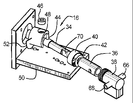
Figs. 16 and 17 show two nutating pump adjustment mechanisms. Referring to
Fig. 16, the first
adjustment mechanism adjusts the angle between the shaft 56 of the stepper
motor 26 and the longitudinal
axis of the piston 34 and the housing 78. Adjusting the angle piston/stepper
motor angle affects the output
of the nutating pump. An angle adjuster bracket 100 is attached to the stepper
motor 26 and has a hinged
portion 102 mounted to the piston housing 78. An actuator 104 is mounted to
the angle, adjuster bracket 100
and is operatively engaged with the hinged portion 102 to pivot the housing 78
and piston 34 assembly, as
desired. The spherical bearing 46, which is engaged with the piston 34 by the
pin 44, allows the piston 34
to pivot relative to a piston driver 106, which is engaged with and rotated by
the stepper motor shaft 56: The
actuator is electrically connected to and controlled by the computer control
system 14. Accordingly, the angle
between the piston 34 and the motor shaft 56 is automatically controlled and
manual adjustment of the angle
is not required. Also, the output profile of the nutating pump is
automatically controlled by the computer
control system 14. Suitable actuators include solenoids, cams, stepper motors,
linear actuators, and other
actuators.
Referring to Figs. 16 and 17, the second nutating pump adjustment mechanism
adjusts the radial
distance that the spherical bearing 46 is offset from the axis of the stepper
motor shaft 56. By adjusting the
spherical bearing / shaft offset the linear movement of the piston 34 sliding
into and out of the housing 78 is
increased or decreased, which affects the nutating pump output. In this
manner, the output of the nutating
pump can be adjusted as desired.
19
CA 02423349 2003-03-20
WO 02/25225 PCT/USO1/29355
The piston driver 106 has a stationary member 108 fixed to the stepper motor
shaft 56. An
adjustable member 110 has a bore 112 which receives the stationary member 108
such that the adjustable
member 110 slides relative to the stationary member 108. A lock screw 114
extends through an adjustment
slot 116 and is engaged with the stationary member 108. The lock screw 114 is
loosened to allow sliding of
the adjustable member 110 relative to the stationary member 108, and then
tightened to secure the stationary
and adjustable members 108, 110 together. The adjustable member 110 carries
the spherical bearing 46. As
the adjustable member 110 is slid, the offset distance of the spherical
bearing 46 relative to the stepper motor
shaft 56 is adjusted as desired. By using a reverseable drive it is also
possible to provide a slight draw-back
at the end of any dispense. Due to the viscosity of the fluids being
dispensed, a greater or lesser amount of
fluid may remain at the dispense outlet opening in the form of a partial drop.
This can allow a post dispense
fluid drip to occur.
By partially reversing the drive after a dispense, the fluid forming at the
dispense outlet opening can
be drawn back. Due to the very small increments of piston movement available
utilizing the drive system
described in this invention, it is possible to provide draw-back with a fine
degree of control. For example,
only ~/~ step may be sufficient for small dispense orifices.
Where desired, the draw-back reverse rotation can be retained in control or
memory and provide
an automatic adjustment for the next dispense operation. Such memory retention
would be advantageous
where a larger draw-back has been provided. For example, if a multi-step draw-
back is used to assure no drip
at the dispense orifice, this would indicate that the fluid remaining in the
conduit from the pump to the
dispense orifice is less than the volume of the tube after draw-back. This
quantity can then be automatically
added to the next dispense calculation.
CA 02423349 2003-03-20
WO 02/25225 PCT/USO1/29355
While the presently preferred embodiments have been illustrated and described,
numerous changes
and modifications can be made without significantly departing from the spirit
and scope of this invention.
Therefore, the inventors intend that such changes and modifications are
covered by the appended claims.
21