Note: Descriptions are shown in the official language in which they were submitted.
CA 02423500 2003-03-25
WO 02/27964 PCT/USO1/30765
-1-
COMMUNICATION SYSTEM
Field Of The Invention
The field of the present invention is wireless communication systems. More
particularly, the present invention relates to dynamic RF power management for
use with an
ultra-wideband communication system.
Background Of The Invention
Wireless communication systems are changing the way people work, entertain
themselves, and communicate with each other. For example, the wide acceptance
of mobile
devices, such as the portable phone, has enabled great mobility while enabling
easy voice
and data communication with family, friends, and co-workers. As more features
are added
to these mobile wireless devices, users are able to receive a wider variety of
information to
facilitate enhanced entertainment and to more efficiently solve business
problems. Data,
such as computer files, graphics, video, and music may now be sent from a
remote location
and received at mobile wireless devices. Such wide area uses generally require
a series of
fixed transceivers arranged to communicate with the mobile wireless devices.
In such a
manner, the wireless device is enabled to communicate so long as the wireless
device
remains in contact with at least one of the fixed transceivers.
Not only is the use of such wide area systems expanding, but the use of local
wireless communication systems is also growing. For example, wireless devices
in a single
building, such as a residence, may be configured to share information. Such
local wireless
communication systems may enable computers to control peripherals without
physical
connections, stereo components to communicate, and almost any appliance to
have access
to the Internet to send and receive information.
The amount of data being sent on both wide and local communication systems is
mushrooming, and may quickly exceed the bandwidth available in the traditional
communication bands. It has been recognized that a relatively new
communication
technology, "ultra-wideband" may provide assistance in meeting the ever
increasing
CA 02423500 2003-03-25
WO 02/27964 PCT/USO1/30765
-2-
bandwidth demands. For example, U.S. Patent No. 6,031,862, entitled "Ultra-
wideband
Communication System and Method", discloses a communication system using an
impulse
radio system. Impulse radio is a form of ultra-wideband communication using
individually
pulsed monocycles emitted at fractions of nanosecond intervals to transmit a
digital signal.
The pulses are transmitted at extremely low power density levels, for example,
at less than -
30 db to -60 dS. The generated pulses are so small that they typically exist
in the noise
floor of other more traditional communication systems.
An ultra-wideband communication system enables communication at a very high
data rate, such as 100 megabit per second or greater, when operated in a small
local area.
However, since the ultra-wideband communication system needs to avoid
interfering with
the more established cormnunication frequencies, the ultra-wideband system
must operate at
extremely low power, typically transmitting signals at the noise level.
Accordingly, each
ultra-wideband cell is severely restricted in size as compared to the more
traditional
continuous wave or carrier based systems.
Since each cell is so small in an ultra-wideband communication system, the
system
must have many fixed antenna sites to cover a geographic area. With so many
antennae
operating simultaneously, mobile transceivers are likely to be receiving
communication
signals from several transmitters including transmitters in adj acent cells
and transmitters in
more distant cells. With every cell potentially receiving signals from so many
transmitters,
communication channels must be geographically separated to minimize the
occurrence of
channel interference. For example, if a particular channel is used in cell,
that channel may
not be usable in any other cell within several miles. Accordingly, since only
a relatively
small subset of communication channels is available in each cell, the
bandwidth of the
overall communication system is substantially reduced.
Also, wireless communication systems suffer from a "near-far" problem, where a
near transmitter's signal can overpower and saturate a receiver while a far
transmitter's
signal may be too weak to be reliably received. Since an ultra-wideband
communication
system has.so many antenna sites, the severity of the near-far problem is
exacerbated.
In any known conventional cell, utilized bandwidth varies as a function of
user demand. Since user demand can vary greatly from one time period to
another, there
are likely to be times when a particular cell is greatly under-utilized, and
other times when
that same cell is saturated, thereby causing undesirable drops in
transmissions, connection
CA 02423500 2003-03-25
WO 02/27964 PCT/USO1/30765
-3-
refusals, and quality degradation. In conventional communication signals, when
a cell's
bandwidth utilization exceeds system quality standards , the system operator
typically will
add another cell in the area to move some of the user traffic from the over-
utilized cell to
the new cell. However, adding cells and antennas can be a costly and time
consuming
process.
Although ultra-wideband has the ability to greatly decrease the impact of
multipath interference, it is still subject to attenuation of the received
signal as it traverses
the distance between transmitter and receiver. For a point RF source, received
signal
strength varies as the inverse of the squared distance for open line of sight
communications.
In cluttered and mobile environments, the attenuation is more closely
proportional to the
inverse of the fourth power of the distance due to multipath cancellation,
which is still
present even in ultra-wideband signals. In either scenario, the attenuation of
the signal can
decrease the signal level to a value that is unsuitable for reliable data
transfer. Due in part
to the deficiencies described above, convention known ultra-wideband
communication
systems do not enable efficient utilization of bandwidth and system resources.
Summary Of The Invention
It is an object of the present invention to provide an ultra-wideband
communications
system that enables greater system efficiency and increases bandwidth
utilization. To meet
the stated objective, and to overcome the disadvantages in known communication
systems,
an ultra-wideband communication system is disclosed.
Briefly, the ultra-wideband communication system includes a transceiver
configured
to receive an ultra-wideband communication signal, which has embedded power
level data.
A measurement circuit in the transceiver measures the strength of the received
signal. An
attenuation factor is computed that compares the measured signal strength to
the data
embedded in the signal. An adaptive circuit uses the attenuation factor to
select a power
level for a next transmission. In a preferred configuration, the transceiver
also has a
positioning circuit that is used to accurately determine the distance from the
transceiver to
the source of the communication signal, and the adaptive circuit uses the
distance to tune
the power level for the next transmission.
Advantageously, the ultra-wideband communication signal enables accurate
selection of power levels to optimize the efficiency of the communication
system. More
CA 02423500 2003-03-25
WO 02/27964 PCT/USO1/30765
-4
particularly, the accurate selection of the lowest acceptable power level
minimizes
interference between communication cells, thereby increasing reliability and
optimizing
bandwidth utilization.
These and other features and advantages of the present invention will be
appreciated
from review of the following detailed description of the invention, along with
the
accompanying figures in which like reference numerals refer to like parts
throughout.
Brief Description Of The Drawings
FIG. 1 is a block diagram of an ultra-wideband communication system in
accordance with the present invention;
FIG. 2 is a flowchart of a method of using an ultra-wideband communication
system
in accordance with the present invention;
FIG. 3 is an illustration of using an ultra-wideband communication system in
accordance with the present invention to adjust cell size;
FIG. 4 is an illustration of example of discrete non-linear power levels for
transmission power in accordance with the present invention;
FIG. 5 is a flowchart of an adaptive power regulation method in accordance
with the
present invention; and
FIG. 6 is a flowchart of another adaptive power regulation method in
accordance
with the present invention.
Detailed Description Of The Invention
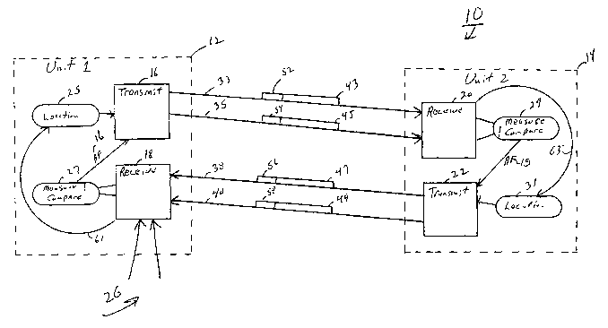
Referring now to FIG. l, an ultra-wideband communication system 10 in
accordance
with the present invention is illustrated. The ultra-wideband communication
system 10
generally comprises a plurality of ultra-wide transceivers configured to
transmit and receive
ultra-wideband communication signals. The communication system 10 employs a
method
of adjusting the power level of transmitted communication signals to reduce
transmission
power levels to the lowest acceptable level. In a particular example, the
power level is first
roughly selected to be at one of a limited number of values, and then fine-
tuned to a more
optimal level.
CA 02423500 2003-03-25
WO 02/27964 PCT/USO1/30765
-5-
Since preferably the power level is continually monitored and adjusted, the
entire
com~.nunication system 10 operates with an efficiency and bandwidth
availability not
achieved in known conventional communication systems. For example, by reducing
transmit power levels, greater chamlel re-use is permitted, with a
corresponding increase in
available system bandwidth. Further, since signal strength at a particular
receiver is more
uniform, the undesirable effects of the near-far problem are reduced.
FIG. 1 illustrates a transceiver unit 12 and a transceiver unit 14. In the
illustration,
transceiver units 12 and 14 are similar; however, it will be appreciated that
the transceiver
units may be alternatively constructed. The transceiver units are constructed
to be
positioned in a wireless ultra-wideband communication device such as a mobile
phone,
mobile Internet device, portable radio, personal data assistant, or a fixed
antenna cell site,
for example.
Transceiver unit 12 includes a transmit circuit 16. The transmit circuit 16 is
constructed to generate an ultra-wideband communication signal such as signal
33. The
transmit circuit 16 generates signal 33 at a selectable power level. For
example, the signal
may be set to one of a discrete number of power levels. To facilitate
selecting the lowest
acceptable power level for future transmissions, information regarding the
selected power
level is embedded in the signal 33. In a preferred embodiment, the signal 33
transmits
digital data communication information, which may be packetized according to
known
techniques. Accordingly, the power level set for transmitting signal 33 is
communicated via
power factor 52. One or more data packets, such as data packet 43, may contain
the power
factor 52 in the data packet 43 header information, for example. ~ In a most
preferred
embodiment, the power factor 52 is a six bit representation of the power level
used to
transmit signal 33. Accordingly, the signal 33 can be transmitted at one of
sixty-four
selectable power levels.
Signal 33 is received by a receiver, such as ultra-wideband receiver 20 in
transceiver
14. Receiver unit 20 is coupled to measure and compared circuitry 29, which
measures the
strength of the received signal 33. For example, the measure and compare
circuit 29 may
measure the peak voltage on the received signal. It will be appreciated that
several
alternatives exist for measuring the strength of the received signal 33.
The receive circuit 20 and the measure and compare circuit 29 also cooperate
to
decode the power factor 52 from the data packet 43, and compare the measured
strength of
CA 02423500 2003-03-25
WO 02/27964 PCT/USO1/30765
-6-
signal 33 against the decoded power factor 52, which represents the power at
which signal
33 was initially transmitted. Using the decoded power factor 52 and the
measured signal
strength of the received signal, an attenuation factor 15 is calculated.
Attenuation factor 15
is fed back into transmit circuit 22, where the attenuation factor is used to
select a power
level to transmit signal 38. Accordingly, adaptive power regulation is
provided. For
example, if the attenuation factor 15 indicates that the received signal is
stronger than
necessary for reliable communication, then the transmit circuit 22 can select
a substantially
lower power level to transmit signal 38. However, if the attenuation factor
shows such a
high attenuation that the signal is barely discernable, then the transmit
circuit 22 can adjust
the power of signal 38 to a higher level. The power level selected by transmit
circuit 22 is
encoded into power factor 56 in data packet 47 which is communicated to
receiver circuit
18.
As described above with reference to receiver 20, receiver 18 accepts signal
38 and
uses measure and compare circuitry 27 to determine an attenuation factor 16.
Attenuation
factor 16 is fed back into transmit circuit 16 for selecting the power level
for signal 35. As
described above, the power factor selected for signal 35 is embedded as power
factor 54
into data packet 45, which is then transmitted back to receiver 20. This
iterative process
continues with each new attenuation factor being fed back into transmit
circuit 22, which
then selects the power level for signal 40, with the power level of signal 40
embedded in
data packet 49 as power factor 58. Accordingly, with only a few communication
iterations,
the lowest selectable power level having acceptable attenuation is used for
establishing the
communication link between two transceivers.
However, the selected power is selected to be at, for example, one of sixty-
four
selectable power levels. It is preferable that the transmit power level be
more accurately set
to assure the lowest practical power level is selected for transmission.
Accordingly,
transceiver units 12 and 14 include location circuits 25 and 31, respectively,
which are used
to accurately determine the geographical position of each of the transceiver
units.
It is a well known feature of ultra-wideband communication systems that highly
accurate geographical positional information is discernable from signals
received from at
least three ultra-wideband transmitters having known geographical position.
Typically, the
transceiver having an unknown location receives ultra-wideband signals from
three fixed
ultra-wideband transmitters, with the signals sent from each transmitter
embedding the
CA 02423500 2003-03-25
WO 02/27964 PCT/USO1/30765
geographical position of each respective transmitter. Using the known position
of each
fixed transmitter, and measuring the slight timing variations between received
signals, the
device with an unknown geographical location can triangulate and accurately
determine its
geographical position. Using such triangulation procedures, an ultra-wideband
device can
determine its geographical position to within a few centimeters, for example.
The location circuitry, such as location circuitry 25, receives signal 38 from
transceiver 14, which may be a fixed site having a known geographical
location, and from
signals 26 from at least two other fixed ultra-wideband transmitters (not
shown). The
location circuitry 25 uses the timing relationships and location information
in these signals
38 and 26 to accurately determine a location for the transceiver unit 12. With
the exact
location of the transceiver unit known, and the location of the fixed
transmitters known, the
location circuitry 25 and 31 can 'precisely determine the distance from the
transceiver to the
fixed transmitter. This distance information is also fed back to the transmit
circuit 16. The
distance information is then used to more accurately adjust the level of power
the transmit
circuit 16 uses to transmit the next signal.
It will be appreciated that although FIG. 1 shows a communication system 10
with
communication established between two transceivers, that such communication
may also be
established between a mobile transceiver and a fixed transceiver unit. It will
also be
appreciated that the preferred embodiment initially uses 32 different
selectable power levels
to transmit each signal, but other numbers of selectable power levels may be
used.
Referring now to FIG. 2, a method 80 of using an ultra-wideband communication
system is described. Method 80 initially sets a power level for a signal and
encodes that
power level in a data packet to be transmitted with the signal as shown in
block 82. The
signal having the encoded power level is transmitted to a receiver in block
84. Block 86
shows that the receiver measures the power level of the signal and extracts
the encoded
power level from the data packet. The measured power level is compared to the
encoded
power level and an attenuation factor is calculated in block 88.
The attenuation factor is used to determine a new power level as shown in
block
102. The attenuation factor may also be used to generally calculate a distance
from the
source of the transmitted signal to the receiver of the signal. This estimated
distance may be
used in a later calculation to more carefully tune the power level. With the
new power level
CA 02423500 2003-03-25
WO 02/27964 PCT/USO1/30765
_g_
determined, the next signal is transmitted at the new selected power level as
shown in block
104.
In a preferred embodiment, the receiver also receives signals from multiple
transmitters, such as three fixed transmitters as shown in block 89. Using the
signals'
timing relationship and embedded positional information, an absolute
geographic position
for the remote device is determined as shown in block 90. Alternatively, an
absolute
geographical position can be assigned to a fixed receiver as shown in block
92. The
geographical position of the fixed transmitter is communicated to the receiver
as shown in
blocks 94 and 96. Preferably, the position is encoded in a data packet which
is
communicated on the ultra-wideband signal sent from the transmitter to the
receiver. Since
the receiver now knows its absolute position and has received encoded
information
regarding the location of the transmitter, in block 98 the two geographical
locations can be
compared. After comparing the two positions, the actual distance between the
transmitter
and receiver can be determined in block 100. The actual distance is then used
to determine
a more tuned power level as shown in block 102. The more finely tuned power
level can
then be used to transmit the next signal using a new power level as shown in
block 104.
In providing the optimal power level setting, the power level is first set to
one of a
set number of available power levels using an iterative communication process.
Subsequent
to selecting a power level, the actual distance between the transmitter and
the receiver is
used in a calculation to more precisely set the power level. It will be
appreciated that the
relationship between distance and transmission power is well known.
Accordingly, the
method of Fig. 2 enables the power level to be precisely minimized to maximize
system-
wide bandwidth, while still assuring reliable corrununication and reducing,
undesirable near-
far effects. .
Referring now to FIG. 3, a particular use of an ultra-wideband communication
system 120 is described. Communication system 120 includes fixed transmitter
122 and
fixed transmitter 124. Fixed transmitter 122 has an original cell size 126
indicated by a
generally circular line on FIG. 3, while fixed transmitter 124 has an original
cell size 132.
Mobile users such as users 133, 134, and 136 are scattered within cells 126
and 132.
Control circuitry at one or both of the fixed transceivers 122 and 124 monitor
the bandwidth
being utilized in each cell. Depending upon bandwidth utilization, the cell
size can be
adjusted to include more users in a cell or exclude users from a cell. For
example, if fixed
CA 02423500 2003-03-25
WO 02/27964 PCT/USO1/30765
-9-
transceiver 122 is monitored and found to be nearing its bandwidth capacity,
fixed
transceiver 122 can be instructed to transmit at a lower power, thereby
effectively reducing
the original cell 126 to a reduced cell size 128. Since new cell size 128 is
smaller, it
contains fewer users which will thereby reduce the amount of bandwidth used at
fixed
transceiver 122. However, in transitioning from original cell size 126 to new
cell size 128,
certain users were abandoned from fixed transceiver 122, such as abandoned
user 133.
Accordingly, as fixed transceiver 122 is reducing its transmitted power
levels, adjacent
fixed transceiver 124 would be instructed to increase its power level
transmissions to
include the abandoned users such as abandoned user 133. In such a manner,
original cell
size 132 is expanded to new cell size 130. By increasing the number of users
in cell 130,
the bandwidth utilization by fixed transceiver 124 is increased. By
dynamically monitoring
the bandwidth of adjacent cells, and dynamically adjusting the power level
transmitted from
the fixed transceivers, bandwidth usage can be leveled across a communication
system 120,
resulting in greater overall system bandwidth.
In a particular example of the present invention, an adaptive power regulation
method is provided to enable robust and reliable ultra-wideband
communications.
Generally, the adaptive power regulation method determines the attenuation
caused by the
transmission path and adjusts the power level of the transmission adaptively
based on this
attenuation. The adaptive power regulation method is more fully described
below.
In the adaptive power regulation method, a key sequence synchronizes
transmitter
and receiver and allows the receiver to sense the attenuation suffered by the
transmission.
This key sequence can encompass one or more UWB pulses. If the key sequence
contains
only one pulse, then it must be of fixed amplitude, and the receivers must
know this value.
If a sequence of pulses is used, the transmit power level is encoded in the
sequence. The
encoding of this information is made totally independent of the amplitude of
the individual
pulses and is preferably implemented by using a digital representation of the
predefined
power levels.
It is preferable to have a multitude of predefined power levels. Optimally the
number of predefined power levels should be greater than 16, with 64 levels
being a suitable
discretization. The levels need not fall in a linear sequence, and a sequence
that is not linear
is better suited to this application. Level 1 is defined as the least
attainable power and level
64 is the highest attainable power. Once a receiver measures the power of and
decodes the
CA 02423500 2003-03-25
WO 02/27964 PCT/USO1/30765
-10
key sequence, it can calculate the attenuation produced by the path between
transmitter and
receiver. The receiver can then respond to the key sequence by boosting its
output to a level
that overcomes the attenuation.
The system is constrained by the need to initially limit the transmitted power
of the
key sequence in order to avoid interfering with other devices. For this
reason, the initial
power level before the first communication is established should be around 32
(in the
middle of the range). FIG. 4 shows a suitable discretized power curve. It can
be seen that
the curve is designed to overcome inverse square attenuation (or inverse
quartic attenuation
if designed for indoor environments) in its middle region. It is also designed
to rapidly
scale up the power if, after several level increases, no intelligible reply
has been obtained. It
is expected that in most circumstances, the receiver will have to boost its
output several
levels to overcome attenuation, but will remain in the middle range.
Inversely, if the initial
power is much too high (a Bit Error Rate (BER) much lower than a predefined
threshold),
then the receiver can jump ~ down to the rapidly decreasing bottom levels. As
a
communication session progresses, the BER and the received power are
continuously
monitored and the power level is adjusted to maintain low BER or reacquire the
signal if it
is lost.
Some communication sessions are less sensitive to BER than others (e.g., video
is
less sensitive than numeric data). This approach takes advantage of this
variable sensitivity
and adjusts the BER threshold based on the data type being transferred.
In this approach, both the receiver and the transmitter store the last power
level used
at the close of a communication session. This power level is then used as the
first
approximation for the power level of the next communication session between
that
particular pair. If no communication has occurred for a predefined amount of
time, then
power level 32 is used instead of the last power level used.
In an environment with multiple transmitter towers, this approach keeps the
top few
power levels available to the tower on reserve. These high power levels can be
used to
overcome mobile obstacles that produce temporary deep fading of the signal.
They can also
be used to allow for adaptive adjustment of the area serviced by the tower.
This use of the
top power levels allows an overburdened tower to hand-off some of its mobile
users to
neighboring towers by stepping back on its power output while the adjacent
towers tap into
their reserved power levels.
CA 02423500 2003-03-25
WO 02/27964 PCT/USO1/30765
-11-
Referring now to FIG. 5, a method 150 of adapting transmission power level for
an
ultra-wideband communication system is shown. In method 150, a communication
is
initiated by user in block 151, for example, by powering up a wireless device.
The wireless
device monitors a command chmnel of a transmitting cell transmitter as shown
in block
153, and in particular, monitors for the key sequence. A received signal from
the
transmitting cell is compared to a threshold level in block 155, and if the
received signal is
above the threshold, the strength of the received signal is measure in block
156. It the
received signal does not meet the minimum threshold, then a default value for
the power
level is selected, as shown in block 158.
Since the signal transmitted from the cell transmitter has an encoded power
level,
the encoded power level, and other information, is decoded from the received
signal in
block 157. Using known techniques, a bit-error-rate (BER) is calculated for
the received
transmission in block 159. The BER is compared to a threshold in block 160. If
the BER is
too high, the system loops back to block 153 to again sample the transmitter
signal. If the
1 S BER is acceptable, then, in block 161, the measured signal strength is
compared to the
power level decoded from the received signal, and an attenuation factor is
calculated. Using
the attenuation factor, a power level is selected for the next transmission.
The selected power level is encoded in the data for the outgoing transmission,
as
shown in block 163, and the selected power level is set on the transmitter in
block 164.
Blocks 165-169 illustrate the selection of the channel that will receive the
next data stream.
If a communication channel has already been selected, then the transmission is
made on that
selected channel, as shown in block 169, or if no channel is yet allocated, a
query
transmission is made on the command channel, as shown in block 168. Either
way, the
transmission is made at the power indicated in block 164.
Referring now to FIG. 6, a method 180 of adapting transmission power level for
an
ultra-wideband communication system is shown. In method 180, the last
successful
transmission power level from a particular device is used to more effectively
set the power
level for the next transmission. As shown in block 181, a particular user or
device receives
an incoming communication or desires to send an outgoing message. The time
since last
transmission is queried in block 182 and compared to a time threshold. The
time threshold
may be set, for example to 1 minute. It will be appreciated that an
appropriate threshold
may be set for different applications and environments.
CA 02423500 2003-03-25
WO 02/27964 PCT/USO1/30765
-12-
If a transmission has been made within the threshold, the last successful
transmission power level is recalled in block 184. If the last transmission is
outside the time
threshold, then the power level is set to a default level as shown in block
183. The selected
power level is encoded into data to be transmitted in block 185, and the data
transmitted at
the selected power level in blocks 187 and 190. A reply to the transmission is
expected in
block 193 and 194. If no response is received, then the power level is
incremented by one
level, up to the maximum level, as shown in block 191. If a reply is received,
then the
power level data from the received signal is decoded in block 197.
An attenuation factor and BER are calculated as described above in blocks 195
and
196, respectively. If the BER is below a minimum threshold level then, in
block 186, the
power level for the next transmission is decremented one level, if possible.
Accordingly,
the method 180 is tuning the transmission power level to the lowest acceptable
level. If the
BER is above the threshold, then block 189 uses the attenuation factor and the
BER to
determine a new power level for the next transmission. For example, if the
attenuation
factor is relatively high, but the BER is only slightly over the BER
threshold, then the
power level may have to be increased only slightly. Since the BER is dependent
not only
on signal quality, but also signal content, the method 180 is able to set the
lowest acceptable
power level to match transmission conditions and signal data content.
One skilled in the art will appreciate that the present invention can be
practiced by
other than the preferred embodiments which are presented in this description
for purposes of
illustration and not of limitation, and the present invention is limited only
by the claims
which follow. It is noted that equivalents for the particular embodiments
discussed in this
description may practice the invention as well.