Note: Descriptions are shown in the official language in which they were submitted.
CA 02423526 2003-03-26
S03P0332
TITLE OF THE INVENTION
RECORDING AND REPRODUCING APPARATUS FOR RECORDING
AND REPRODUCING INFORMATION TO AND FROM A MAGNETO-OPTICAL
STORAGE MEDIUM
BACKGROUND OF THE INVENTION-
Field of the Invention
The present invention relates generally to a
recording and reproducing apparatus for functionally
expanding a magneto-optical disc usable by a conventional
mini-disc (MD) system, the expar~sion being made in such a
manner as to optionally maintain compatibility with the
conventional MD system.
Discussion of the Background
The so-called Mini-disc (MD), a 64 mm-across
magneto-optical disc housed in a cartridge, has gained
widespread acceptance today as a storage medium to and
from which digital audio data are recorded and reproduced.
The MD system adopts ATRAC (Adaptive TRansform
Acoustic Coding) as its audio data compression method.
ATRAC involves compression-coding audio data by what is
called MDCT (Modified Discrete Cosine Transform). The
2
CA 02423526 2003-03-26
audio data has been acquired through a predetermined time
window. Typically, music data are compressed by ATRAC to
one-fifth to one-tenth the original size.
The MD system utilizes a convolution code called
ACIRC (Advanced Cross Interleave Reed-Solomon Code) as
its error correction system and EFM (Eight-to-Fourteen
Modulation) as its modulation technique: ACIRC is a
convolution code that provides dual error correction on
C1 and C2 sequences (in vertical and oblique d.irections).
The method is used to carry out a powerful error
correction process on sequential data such as audio data.
One disadvantage of ACIRC is that it requires a linking
sector arrangement for data update purposes. ACIRC and
EFM are basically the same as those employed in a
conventional compact disc (CD) system.
For music data management, the MD system uses U-TOC
(User TOC [Table of Contents]). Specifically, a U-TOC
area is furnished on an inner side of a recordable area
of the disc. For the current MD system, U-TOC constitutes
the track (audio track/data track) title sequence and
management information that is updated to keep up with
the recording or deletion of such tracks. Under the U-TOC
scheme, each track (i.e., parts constituting each track)
is managed in terms of start position, end position, and
a
CA 02423526 2003-03-26
mode, settings.
The disc for the MD system is small, inexpensive,
and offers good characteristics when used by the system
to record or reproduce audio data. These advantages have
enabled the MD system to gain widespread market
acceptance.
As recognized by the present inventors, MD systems
have not fully achieved their potential in.the market as
they are not compatible with general purpose computers,
such as personal computers. Moreover, convention MD
systems use different file management schemes than the
File Allocation Table (FAT)-based file systems used in
personal computers.
With more general use of personal computers and PC-
based networking, more and more audio data are
distributed over PC-based networks. Today, it is common
practice for the user of a personal computer to use it as
an audio server fxom which to download favorite music
files to a portable data reproducing apparatus for music
reproduction. As recognized by the present inventors,
because the conventional MD system is not fully
compatible with personal computers, a new MD system is
desirable that would adopt a general-purpose management
system, such as a FAT (File Allocation Table) system, to
3
CA 02423526 2003-03-26
enhance PC-compatibility.
As explained in White, R., "How Computers Work,
Millennium Edition" Que Corporation; pages 146 and 158
for example, 1999, the entire contents of which being
incorporated herein by reference, the FAT is created by
the disk drive on a particular disk sector, such as
sector 0 . The term "FAT" (or °'FAT System°° ) is used
generically herein to describe various PC-based file
systems, and is intended to cover the specific FAT-based
file systems used in DOS, VFAT (virtual FAT) used in
Windows 95/98, FAT 82 used in Windows 98/ME/2000, as well
as NTFS (NT file system; sometimes New Technology File
System) which is the file system used by Windows NT
operating system, or optionally in Windows 2000 operating
system, for storing and retrieving files on read/write
disks. NTFS is the Windows NT equivalent of th.e Windows
95 file allocation table (FAT) and the OS/2 High
Performance File System (HPFS) .
Meanwhile, a higher degree of compatibility with
personal computers means increased risk of unauthorized
copying of copyrighted works, which in-turn requires
better techniques to protect against unauthorized copying
of audio works. One technological way of reinforcing
copyright laws involves encrypting the audio works when
4
CA 02423526 2003-03-26
recorded. It is also desired that music titles and artist
names recorded on the disc be managed in a more efficient
manner than at present.
The current MD system uses a disc with a storage
capacity of about 160 MB, which, as recognized by the
present inventors, is not always sufficient fo:r the
user's requirement for data storage. It is thus desired
that the storage capacity of a new disc be. boosted while
remaining backwards-compatible with the current MD system.
SUMMARY OF THE INVENTION
It is therefore an object of the present invention
to overcome the above and other deficiencies of the
related art and to provide a reproducing and recording
apparatus for efficiently managing audio data through the
integration of the FAT system on MD media. Alternatively,
other media formats be used as well in light of the
teachings of the present disclosure.
While a "summary'° of selected aspects of the
invention are provided below, this summary is not
intended to be an exhaustive listing of all novel
attributes and combination of attributes of the present
invention. Nor is this summary intended to be construed
independent of the other aspects of the present
CA 02423526 2003-03-26
disclosure.
In carrying out the invention and according to one
aspect thereof, there is provided an information
recording/reproducing apparatus for recording and
reproducing information to and from a magneto-optical
storage medium that includes a first magnetic layer for
recording at least information, a second magnetic layer
for regulating a switched connective force, and a third
magnetic layer for shifting a magnetic wall of recorded
markings for information reproduction, the three layers
being stacked on a transparent substrate to make up the
storage medium, the information recording/reproducing
apparatus includes an optical head and. a magnetic head.
The optical head has a light source and an objective
lens, the light source is configured to emit at least a
laser beam with a wavelength of about 780 nm, the
objective lens having a numerical aperture of about 0.45
and is configured to focus the laser beam from the light
source into a beam spot for. emission onto the magneto-
optical storage medium; and
a magnetic head for applying a recording magnetic
field to the magneto-optical storage medium.
Another feature of the present invention is that the
optical head and the magnetic head are configured to
6
CA 02423526 2003-03-26
generate minuscule markings on the first.magnetic layer
of the magneto-optical storage medium by a laser pulse
magnetic field modulation technique so as to record
information on the magneto-optical storage medium, and
the optical head is configured to emit the light beam
onto the magneto-optical storage medium when a
predetermined temperature is reached so that the second
magnetic layer becomes magnetically neutral and magnetic
walls in the first magnetic layer are transferred into
the third magnetic layer so that the minuscule markings
become visible under a beam spot on the magnet-optical
storage medium and enabling the markings to be detected.
Another feature of the present invention is that the
optical head and the magnetic head are configured to
record and reproduce information to and from another
magneto-optical storage medium that includes a dielectric
film, a magnetic film, another dielectric film, a
reflective film, and a protective film stacked on a
transparent polycarbonate substrate.
Still another feature of the present invention is
that it may include a turntable configured to Load the
magneto-optical storage medium and the another magneto-
optical storage medium into a recording/reproducing
position, and is configured to rotate the storage medium
7
CA 02423526 2003-03-26
at a linear velocity corresponding to the respective
storage mediums loaded on the turntable.
Yet another feature of the present invention is that
the turntable may be configured to rotate the magneto-
optical storage medium at a linear velocity that is
within an approximate inclusive range of 1.85 m/s through
2.06 m/s, and is configured to rotate the another
magneto-optical storage medium at a linear~velocity that
is within an approximate inclusive range of 2.4 m/s
through 2.8 m/s.
A further feature of the present invention is that
the turntable may be configured to rotate the another
magneto-optical storage medium at a -linear velocity that
is within an approximate inclusive range of 1.2 m/s
through 1.4 m/s.
Still a further feature of the present invention is
that the magneto-optical storage medium and the another
magneto-optical storage medium each being a disc of a
first same size accommodated in a cartridge of a second
same size.
Still further, a feature of the present invention is that
the disc has a diameter of 64.8mm, a diameter of a center
hole of llmm, a thickness of l.2mm, and a cartridge size
of 68D x 72W x 5H mm.
8
CA 02423526 2003-03-26
According to this invention, a track information
file and an audio data file may be generated on a disc
serving as the storage medium. These are the files
managed by the so-called FAT system.
The audio data file is a file that accommodates a
plurality of audio data items. When viewed from the FAT
system, the audio data file appears to be a very large
file. The composition of this file is divided into parts,
so that audio data are handled as a set of such parts.
The track information file is a file that describes
various types of information for managing the audio data
contained in the audio data file. The track index file is
made up of a play order table, a programmed play order
table, a group information table, a track information
table, a part information table, and a name table.
The play order table indicates the order of audio
data, reproduction defined by default. As such, the play
order table contains information representing links to
track descriptors corresponding to track numbers (i.e.,
music title numbers) in the track information table.
The programmed play order table contains the order
of audio data reproduction defined by the individual user.
As such, the programmed play order table describes
programmed track information representing links to the
9
CA 02423526 2003-03-26
track descriptors corresponding to the track numbers.
The group information table describes information
about groups. A group is defined as a set of one or more
tracks having serial track numbers, or a set of one or
more tracks with programmed serial track numbers.
The track information table describes information
about tracks representing music titles. Specifically, the
track information table is made up of track. descriptors
representing tracks (music titles). Each track descriptor
describes a coding system, copyright management
information, content decryption key information, pointer
information pointing to the part number serving as the
entry to the music title of the track in question, an
artist name, a title name, original title order
information, and recording time information about the
track in question.
The part information table describes pointers
allowing part numbers to point to actual music title
locations. Specifically; the part information table is
made up of part descriptors corresponding to individual
parts. Entries of part descriptors are designated from
the track information table. Each part descriptor is
composed of a start address and an end address of the
part in question in the audio data file, and a link to
CA 02423526 2003-03-26
the next part.
When audio data are desired to be reproduced from a
particular .track, information about the designated track
number is retrieved from the play order table. The track
descriptor corresponding to the track from which to
reproduce the audio data is then acquired.
Key information is then obtained from the
applicable track descriptor in the track information
table, and the part descriptor indicating the area
containing entry data is acquired. From the-part
descriptor, access is gained to the location, in the
audio data file, of the first part containing the desired
audio data, and data are retrieved from the accessed
location. The reproduced data from the location are
decrypted using the acquired key information far audio
data reproduction. If the part descriptor has a link to
another part, the linked part is accessed and the above
steps are repeated.
BRIEF DESCRIPTION OF THE DRAWINGS
These and other objects of the invention will be
seen by reference to the description; taken in connection
with the accompanying drawing, in which:
Fig. 1 is an explanatory view of a disc for use
I1
CA 02423526 2003-03-26
with a next-generation MD1 system;
Fig. 2 is an explanatory view of a recordable area
on the disc for use with the next-generation MDl system;
Figs. 3A and 3B are explanatory views of a disc for
use with a next-generation MD2 system;
Fig. 4 is an explanatory view of a recordable area
on the disc for use with the next-generation MD2 system;
Fig. 5 is an explanatory view of amerror-
correcting code scheme for use with the next-generation
MDl and MD2 systems;
Fig. 6 is another explanatory view of the error-
correcting code scheme for use with the next-generation
MD1 and MD2 systems;
Fig. 7 is another explanatory view of the error-
correcting code scheme for use with the next-generation
MD1 and MD2 systems;
Fig. 8 is a perspective view of a disc portion
showing how an address signal is generated using wobbles;
Fig. 9 is an explanatory view of an ADIP signal for
use with the current MD system and the next-generation
MD1 system;
Fig. 10 is another explanatory view of the ADIP
signal for use with the current MD system and the next-
generation MD1 system;
12
CA 02423526 2003-03-26
Fig. 11 is an explanatory view of an ADIP signal
for, use with the next-generation MD2 system;
Fig. 12 is another explanatory view of the ADIP
signal for use with the next-generation MD2 system;
Fig. 13 is a schematic view showing relations
between the ADIP signal and frames for the current MD
system and the next-generation MD1 system;
Fig. 14 is a schematic view indicating relations
between the ADIP signal and frames for the next-
generation MD1 system;
Fig. 15 is an explanatory view of a control signal
for use with the next-generation MD2 system;
Fig. 16 is a block diagram of a disc drive unit;
Fig. 17 is a block diagram of a media drive unit;
Fig. 18 is a flowchart of steps for initializing a
next-generation MD1 disc;
Fig. 19 is a flowchart of steps for initializing a
next-generation MD2 disc;
Fig. 20 is an explanatory view of a signal
recording bitmap;
Fig. 21 is a flowchart of steps for reading data
from a FAT sector;
Fig. 22 is a flowchart of steps for writing data to
a FAT sector;
Z3
CA 02423526 2003-03-26
Fig. 23 is a flowchart of steps in which the disc
drive unit alone reads data from a FAT sector;
Fig. 24 is a flowchart of steps in which the disc
drive unit alone writes data to a FAT sector;
Fig. 25 is a flowchart of steps for generating a
signal recording bitmap;
Fig. 26 is another flowchart of steps for
generating the signal recording bitmap;
Fig. 27 is another flowchart of steps for
generating the signal recording bitmap;
Fig. 28 is an explanatory view of a first example
of an audio data management system;
Fig. 29 an explanatory view of an audio data file
for use with the first example of the audio data
management system;
Fig. 30 is an explanatory view of a track index
file, for use with the first example of the audio data
management system;
Fig. 31 is an explanatory view of a play order
table for use with the first example of the audio. data
management system;
Fig. 32 is an explanatory view of a programmed play
order table for use with the first example of the audio
data management system;
14
CA 02423526 2003-03-26
Figs. 33A and 33B are explanatory views of a group
information table for use with the first examp7_e of the
audio data management system;
Figs. 34A and 34B are explanatory views of a track
information table for use with the first example of the
audio data management system;
Figs. 35A and 35B are explanatory views of a part
information table for use with the first example of the
audio data management system;
Figs. 36A and 36B are explanatory views of a name
table for use with the first example of the audio data
management system;
Fig. 37 is an explanatory view of typical
processing performed by the first example of the audio
data management system;
Fig. 38 is an explanatory view showing how each
name slot in the name table is accessed from a plurality
of ,pointers;
Figs. 39A and 39B are explanatory views of a
process performed by the first example of the audio data
management system to delete parts from the audio data
file;
Fig. 40 is an explanatory view of a second example
of the audio data management system;
CA 02423526 2003-03-26
Fig. 41 an explanatory view of an audio data file
for use with the second example of the audio data
management system;
Fig. 42 is an explanatory view of a track index
file for use with the second example of the audio data
management system;
Fig. 43 is an explanatory view of a play order
table for use with the second example of the audio data
management system;
Fig. 44 is an explanatory view of a programmed play
order table for use with the second example of the audio
data management system;
Figs. 45A and 45B are explanatory views of a group
information table for use with the second example of the
audio data management system;
Figs. 46A and 46B are explanatory views of a track
information table for use with the second example of the
audio data management system;
Figs. 47A and 47B are explanatory views of a name
table for use with the second example of the audio data
management system;
Fig. 48 is an explanatory view of typical
processing performed by the second example of the audio
data management system;
16
CA 02423526 2003-03-26
Fig. 49 is an explanatory view showing how the
second example of the audio data management system
divides one file data item into a plurality of indexed
areas using an index scheme;
Fig. 50 is an explanatory view depicting how the
second example of the audio data management system
connects tracks using the index scheme;
Fig. 51 is an explanatory view indicating how the
second example of the audio data management system
connects tracks using another scheme;
Figs. 52A and 52B are explanatory views sketching
how management authority is moved between a personal
computer and a disc drive unit connected therewith
depending on the type of data to be written to a disc
loaded in the drive unit;
Figs. 53A, 53B, and 53C are explanatory views
illustrating an audio data check-out procedure;
Fig. 54 is a schematic view portraying conceptually
how the next-generation ~Dl system and the current MD
system may coexist in the disc drive unit;
Fig. 55 is an external view of a portable disc
drive unit;
Fig. 56 is a flowchart of steps carried out by the
disc drive unit in formatting a disc loaded therein;
17
CA 02423526 2003-03-26
Fig. 57 is a flowchart of steps carried out by the
disc drive unit in formatting a virgin disc loaded
therein;
Fig. 58 is a flowchart of steps carried out by the
disc drive unit in recording audio data to a disc loaded
therein; and
Fig. 59 is a flowchart of steps for switching from
the disc format of the next-generation MDl~system to the
disc format of the current MD system.
DESCRIPTION OF THE PREFERRED EMBODIMENTS
The following description is divided i:~.to the following
10~ sections
1. Outline of the recording system
2. Discs
3. Signal formats
4. Structure of the recording/reproducing apparatus
5. Initialization of next-generation MD1 and MD2
discs
6. First example of the audio data management system
7. Second example of the audio data management
system
8. Operation during connection with the personal
computer
18
CA 02423526 2003-03-26
9. Restrictions on copying of audio data from the
disc
10. Coexistence of the next-generation MDl system
with the current MD system
1. Outline of the recording system
The recording/reproducing apparatus according to
the present invention uses a magneto-optical disc as its
storage medium. The physical attributes, such as farm-
factor, of the disc are substantially similar to the disc
utilized by so-called MD (Mini-disc) systems. However,
data recorded on the disc and how the data is arranged on
the disc differs from a conventional MD. More
particularly, the inventive apparatus employs a FAT (File
Allocation Table) system as its file management system
for recording or reproducing content data such as audio
data, so that compatibility with existing personal
computers is ensured. Once again, the term "FA.T" (or °°FAT
System°') is used generically herein to describe various
PC-based file systems, and it intended to be descriptive
of the specific FAT structure used in DOS, VFAT (virtual
FAT) used in Windows 95/98, FAT 32 used in Windows
98/ME/2000, as well as NTFS (NT file system; sometimes
New Technology File System) which is the file system used
19
CA 02423526 2003-03-26
by Windows NT operating system, or optionally i.n Windows
2000 operating system, for storing and. retrieving files
on a read/write disks. Compared with the conventional MD
system, the recording/reproducing apparatus of the
invention has an improved error correction system and an
advanced modulation technique designed to boost data
storage capacity and to increase data security.
Furthermore, the inventive apparatus encrypts content
data and takes measures to prevent illegal data copying
and ensure copyright protection for the content data.
Generally, there is two kinds of specifications,
MD1 and MD2, developed by the pr°esent inventors for the
next-generation MD system. The MD1 specifications involve
the use of the same disc (i.e., physical medium) as that
which is currently used by the existing MD system. The
MD2 specifications adopt a disc which has a same form-
factor as, and is identical externally to the disc of the
current MD system, but which utilizes a magnetic super-
resolution (MSR) technique to enhance recording density
in the linear direction, whereby storage capacity is
boosted.
The current MD system utilizes as its storage
medium a 64 mm-across magneto-optical disc enclosed in a
cartridge. The disc is 1.2 mm thick and, has a center hole
CA 02423526 2003-03-26
11 mm in diameter. The cartridge measures 68 mm by 72 mm
by 5 mm.
The dimensions and shapes of the discs and
cartridges are the same as the next-generation MD1 and
MD2 systems. On both the MD1 and MD2 discs, the start
position of the lead-in area is the same as with the
current MD system, i.e., starting at 29 mm.
It is proposed for the next-generation MD2 system
that the track pitch be in an inclusive range of 1.2 a m
through 1.3 ~ m (e. g., 1.25 ~ m). For the next-generation
MDl system with its disc structurally identical to that
of the current MD system, the track pitch is set to 1.6
m. The bit length is set to 0.44 ~ m/bit for the next-
generation MD1 disc and proposed at 0.16 ~ m/bit for the
MD2 disc. Redundancy is set to 20.50a for both the next-
generation MD1 and the next-generation MD2 discs.
The next-generation MD2 disc is arranged to
increase its storage capacity in linear direction by
resorting to the magnetic super-resolution technique. The
MSR technique involves taking advantage of a specific
phenomenon on the disc: that a cut-through layer becomes
magnetically neutral when a particular temperature is
reached, allowing magnetic walls that were transferred to
a regenerative layer to move in such a manner that
21
CA 02423526 2003-03-26
infinitesimal markings are viewed apparently larger under
a beam spot.
That is, the next-generation MD2 disc is
constituted by a magnetic layer acting as a recording
layer f.or recording at least data, by a cut-through layer,
and by a magnetic layer for data regeneration, all
deposited on a transparent substrate. The cut-through
layer serves as a layer that regulates switched
connective force. When a specific temperature is reached,
the cut=through layer becomes magnetically neutral to let
the magnetic walls transferred in the recording layer be
shifted into the regenerative magnetic layer. This allows
infinitesimal markings to become visible under the beam
spot. For data recording, a laser pulse magnetic field
modulation technique is adopted to generate minuscule
markings on the disc.
On the next-generation MD2 disc, grooves are made
deeper than with a conventional MD disc and their
gradient is steeper as well. so as to improve de-track
margins and to reduce land-induced crosstalk, wobble
signal crosstalk, and focus leaks.. Illustratively, the
grooves are in an inclusive range of 160 nm through 180
nm deep, the groove gradient is in an inclusive range of
60 through 70 degrees, and the groove width is in an
22
CA 02423526 2003-03-26
inclusive range of 600 nm through 700 nm on the next-
generation MD2 disc.
As part of its optical specifications, the next-
generation MD1 disc has its laser wavelength ~ set to 780
nm and its numerical aperture NA to 0.45 for an objective
lens in an optical head. Likewise, the next-generation
MD2 disc has its laser wavelength ~ also set to 780 nm
and its numerical aperture NA to 0.45 for the objective
lens in the optical head.
The next-generation MD1 and MD2 systems both adopt
the so-called groove recording system as their recording
scheme. That is, grooves are formed over the disc surface
as tracks for recording and reproduction purposes.
As its error-correcting code system, the existing
MD system utilizes a convolutional code based on ACIRC
(Advanced Cross Interleave Reed-Solomon Code). By
contract, the next-generation MD1 and MD2 systems employ
a block complete code that combines RS-LDC (Reed Solomon-
Long Distance Code) with BIS (Burst Indicator Subcode).
Using the block complete error-correcting code eliminates
the need for linking sectors. Under the error correction
scheme combining LDC with BIS, the location of a burst
error that may occur is detected.by BIS. The error
location is utilized in getting the LDC code to effect
23
CA 02423526 2003-03-26
erasure correction.
Adopted as the addressing system is the so-called
wobbled groove system whereby a single spiral groove is
formed, and both sides of the groove is flanked by
wobbles furnished as address information. This type of
addressing system is called ADIP (Address in Pregroove).
The current MD system and the next-generation MD1 and MD2
systems differ in linear density. Whereas the current MD
system adapts as its error-correcting code a
convolutional code called ACIRC, the next-generation MDl
and MD2 systems are set to use the block complete code
combining LDC and BIS. As a result, the current MD system
and the next-generation MDl and MD2 systems differ in
redundancy and have different relative positions between
ADIP and data. For these reasons, the next-generation MD1
system with its physical disc structurally identical to
that of the current MD system handles the ADIP signal in
a manner different from the current MD system. The next-
generation MD2 system is set to modify its ADIP signal
specifications for better compliance with the next-
generation MD2 specifications.
The current MD system adopts EFM (8 to 14
modulation) as its modulation system, whereas the next-
generation MDl and MD2 systems utilize RLL(1, 7)PP (RLL,
24
CA 02423526 2003-03-26
Run Length Parity Preserve/Prohibit rmtr [repeated
minimum transition Limited; PP, runlength]), called the
1-7 pp modulation system hereinafter. The next-generation
MD1 and MD2 systems use a Viterbi decoding method as
their data detection method, based on partial_ response
PR(1, 2, 1)ML for the MD1 system and on partial response
PR(1, -1)ML for the MD2 system.
The disc driving system adopts either CLV (Constant
Linear Velocity) or ZCAV (Zone Constant. Angular Velocity).
Standard linear velocity is set to 2.4 m/sec for the
next-generation MD1 system and 1.98 m/sec for the next-
generation MD2 system. With the currenc MD system,
standard linear velocity is set to 1.2 m/sec for 60-min
discs and 1.4 m/sec for 74-min discs.
For the next generation MD1 system with its disc
structurally identical to that of the current MD system,
total data storage capacity per disc is about 300
megabytes (on the 80-min disc). Because the 1-7 pp
modulation system is adopted instead of EFM as the
modulation system, window margins are changed from 0.5 to
0.666, whereby recording density is increased by a factor
of 1.33. Since the ACIRC system is replaced by the
combination of BIS with LDC as the error correction
system, data efficiency is boosted, whereby recording
CA 02423526 2003-03-26
density is further increased by a factor of 1.48. Overall,
with the same disc in use; data storage capacity is made
approximately double that of the current MD system.
The next-generation MD2 disc utilizing the magnetic
super-resolution technique is further boosted in
recording density in the linear direction; the total data
storage capacity amounts to about one gigabytes.
At standard linear velocity, the data rate is set
to 4.4 megabits/sec for the next-generation MD1 system
and 9.8 megabits/sec for the next-generation MD2 system.
2. Discs
Fig. 1 shows a typical structure of the next-
generation MD1 disc. This disc is structurally identical
to that of the current MD system. That is, the disc is
made up of a dielectric film, a magnetic film, another
dielectric film, and a reflective film, deposited on a
transparent polycarbonate substrate. The disc surface is
covered with a protective film.
On the next-generation MD1 disc, as shown in Fig. l,
a lead-in area on the innermost side (of the recordable
area, where °'innermost" refers to a radial direction
relative to a center of the disc) has a P-TOC (Pre-
mastered TOC [Table Of Contents]) area. As a physical
26
CA 02423526 2003-03-26
structure, this area constitutes a pre-mastered area.
That is; embossed pits are formed here to record control
information and other related information such as P-TOC
information.
On the outer side, in the radial direction, of the
lead-in area including the P-TOC area is a recordable
area (where magneto-optical recording is possible). This
is a recordable as well as reproducible area including
recording tracks furnished with grooves as their guides.
On the inner side of the recordable area is a U-TOC (User
TOC) area.
The U-TOC area is the same in structure as that of
the current MD system in which disc management
information is recorded. What is held in the U-TOC area
is the order of track (audio track/data track) titles and
management information written over as needed to keep up
with the recording or erasure of such tracks. More
specifically, the management information includes start
and end positions of tracks (i.e., parts making up the
tracks) and mode settings.
An alert track is furnished on the outer side of
the U-TOC area. This track contains an alert sound
recorded thereon that is activated (audibilized) by the
MD player if the disc is loaded into the current MD
27
CA 02423526 2003-03-26
system. The sound indicates a warning that the disc is
for use with the next-generation MD1 system and cannot be
used for reproduction with the current system. The
remaining portion of the recordable area (shown in more
detail in Figure 2) is follcwed in the radial direction
by a lead-out area.
Fig. 2 shows a typical structure of the recordable
area on the next-generation MD1 disc indicated in Fig. 1.
As illustrated in Fig. 2, the beginning of the recordable
area (inner side) has the U-TOC area and the alert track.
A region containing the U-TOC area and alert track has
its data recorded in EFM format so that the data may be
reproduced by current MD system players. On the outer
side of the area of data stored in EFM format is an area
where data are recorded in 1-7 pp modulation format for
the next-generation MDI system. There is a clearance of a
predetermined distance called a "guard band" between the
area of data recordings in EFM format on the one hand,
and the area of data storage in 1-7 pp modulation format
on the other hand. The guard band is intended to prevent
malfunction of the current MD player when the latter is
loaded with a next-generation MD1 system disc.
At the beginning of the area of data recordings in
1-7 pp modulation format Li.e., inner side), there are a
28
CA 02423526 2003-03-26
DDT (Disc Description Table) area arid a reserve track.
The DDT area is designed to replace physically defective
regions and includes a unique ID (UID). The UID is unique
to each storage medium, typically based on randomly
generated numbers. The reserve track is provided to
accommodate information for content protection.
Furthermore, the area of data storage in l-7 pp
modulation format includes a FAT (File Allocation Table)
area. The FAT area is an area that allows the FAT system
to manage data pursuant to FAT system criteria used by
general-purpose computers. More specifically, the FAT
system carries out file managemerit based on FAT chains
involving both a directory indicating the entry points of
root files and directories, and a FAT table describing
FAT cluster link information. Once again, the term FAT is
used in a general sense to refer to a variety of
different file management schemes employed by PC
operating systems
The U-TOC area on the next-generation MD1 disc
records two kinds of information: an alert track start
position, and the start position of the area for data
storage in 1-7 pp modulation format.
When a next-generation MD1 disc is loaded into a
current MD system player; information is read from the U-
29
CA 02423526 2003-03-26
TOC area of the loaded disc. The retrieved U-TOC
information reveals the alert track position, allowing
the alert track to be accessed so that its data will
start being reproduced. The alert track contains data
constituting the alert sound warning that the disc is for
the next-generation MD1 system and cannot be used for
reproduction with the current system.
The alert sound may illustratively articulate a
message like "This disc cannot be used on this player."
Alternatively, the alert sound may also be a simple beep,
tone or other warning signal.
When a next-generation Niul disc is loaded into a
next-generation MD1 system player, information is read
from the U-TOC area of the loaded disc. The retrieved U-
TOC information reveals the start position of the area
where data are stored in 1-7 pp modulation format and
allows data to be read from the DDT, reserve track, and
FAT area. Over the area of data storage in 1-7 pp
modulation format, data management is effected not with
the U-TOC but with the FAT system.
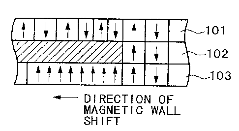
Figs. 3A and 3B show a typical structure of the
next-generation MD2 disc. This disc is also made up of a
dielectric film, a magnetic film, another dielectric film,
and a reflective film, deposited on a transparent
CA 02423526 2003-03-26
polycarbonate substrate. The disc surface is covered with
a protective film.
On the next-generation MD2 disc, as depicted in Fig.
3A, the lead-in area an the inner side (in a radial
direction) has control information recorded using an ADIP
signal. On the MD2 disc, the currently-used P-TOC area of
embossed pits is replaced by the lead-in area having
control information based on the ADLP signal. The
recordable area starting from outside the lead-in area is
a recordable as well as reproducible area that has
grooves formed therein as guides for recording tracks.
The recordable area has data recorded in 1-7 pp
modulation format.
On the next-generation MD2 disc, as indicated in
Fig. 3B, the magnetic film is constituted by a magnetic
layer 101 acting as a recording layer for recording data,
by a cut-through layer 102, and by a magnetic layer 103
for data regeneration, all deposited on the substrate.
The cut-through layer 102_ serves as a layer that
regulates switched connective force. When a specific
temperature is reached, the cut-through layer 102 becomes
magnetically neutral to let the magnetic walls
transferred in the recording layer 101 to be shifted into
the regenerative magnetic layer 103. This allows
31
CA 02423526 2003-03-26
infinitesimal markings in the recording layer 101 to be
viewed as apparently enlarged under the beam spot on the
regenerative magnetic layer 103.
Whether a loaded disc is a next-generation MDl disc
or a next-generation MD2 disc can be determined based on
the information retrieved from the lead-in area.
Specifically, if P-TOC information in embossed pits is
detected from the lead-in area, it means the loaded disc
is a current MD system disc or a next-generation MD1 disc.
If control information based on the ADIP signal is
detected from the lead-in area, with no P-TOC information
in embossed pits detected, it means the disc in question
is a next-generation MD2 disc. However, this manner of
distinguishing the MD1 disc from the MD2 disc is not
limitative of the invention. Alternatively, phase
differences in a tracking error signal between on-track
and off-track modes may be utilized in determining the
disc type. As another alternative, the disc may be given
a detection hole for disc identification purposes.
Fig. 4 shows a typical structure of the recordable
area on the next-generation MD2 disc. As illustrated in
Fig. 4, the recordable area has all its data recorded in
1-7 pp modulation format. A DDT area and a reserve track
are located at the beginning of (i.e., on the inner side
32
CA 02423526 2003-03-26
of) the area where data are recorded in 1-7 pp modulation
format. The DDT area is provided to record alternate area
management data for managing alternate areas intended to
replace physically defective areas. Moreover, the DDT
area includes a management table that manages a
replacement area, which includes a recordable area that
substitutes for the physically defective areas. The
management table keeps track of the logical~cluster(s)
determined to be defective and also keeps tracks of the
logical clusters) in the replacement area assigned to
replace the defective logical clusters. The DDT area also
contains the UID mentianed above. The reserve track
stores information for content protection purposes.
A FAT area is also included in the area with its
data recorded in 1-7 pp modulation format. The FAT area
is used by the FAT system for managing data. The FAT
system, in this embodiment, effects data management
pursuant to the FAT system criteria applicable to
general-purpose personal computers.
No U-TOC area is provided on the next-generation
MD2 disc. When a next-generation MD2 disc is loaded into
a next-generation MD2 player, data are read from the DDT
area, reserve track, and FAT located as described above
on the disc. The retrieved data are used for data
33
CA 02423526 2003-03-26
management by the FAT system.
A time-consuming initialization process is not
needed on next-generation MD1 and MD2 discs. More
specifically, initialization is not required on these
discs except for advance preparation of a DDT area, a
reserve track, and a minimum set of tables including a
FAT table. Data may be directly written to the recordable
area of an unused disc and then read therefrom without
recourse to an initialization process.
3. Signal formats
What follows is a descripticr~ of signal formats for
the next-generation MD1 and MD2 systems. The current MD
system utilizes the convolutional code called ACIRC as
its error correction system in which a 2,352-byte sector
corresponding to the data size of a sub-code block is
regarded as an increment of access far read and write
operations. Because the convolutional code scheme
involves an error-correcting code sequence spanning a
plurality of sectors, it is necessary to provide a
linking sector between adjacent sectors when data are to
be updated. As its addressing system, the current MD
system adopts the wobbled groove scheme called ADIp in
which a single spiral groove is formed, and both sides of
34
CA 02423526 2003-03-26
the groove are flanked by wobbles furnished as address
ir_formation. The current MD system optimally arranges the
ADIP signal for gaining access to the 2,352-byte sector.
The next-generation MDl and MD2 systems, by
contrast, employ a block complete code scheme that
combines LDC with BIS, and regards a &4-kilobyte block as
an increment of access for read and write operations.
Linking sectors are not needed by the block complete code.
This, however, requires that the next-generation MDl
system utilizing the disc of the current MD system
rearrange the ADIP signal in a manner complying with a
new recording method. The next-ger~2ration MD2 system is
set to alter the ADIP signal specifications to comply
with the specifications of the next-generation MD2 system.
Fig. 5, 6, and 7 are explanatory views of the error
correction system for use with the next-generation MD1
and MD2 systems. This error correction system combines an
LDC-based error-correcting code scheme illustrated in Fig.
5, with the BIS scheme shown in Figs. 6 and 7.
Fig. 5 depicts a typical structure of a code block
in the LDC-based error-correcting code scheme. As shown
in Fig. 5, each error-correcting code sector is provided
with a four-byte error detection code EDC, and data are
laid out two-dimensionally in the error-correcting code
CA 02423526 2003-03-26
block that is 304 bytes long horizontally and 216 bytes
long vertically. Each error-correcting code sector is
made up of two-kilobyte data: As illustrated. in Fig. 5,
the 304-byte-by-216-byte error-correcting code block
includes 32 error-correcting code sectors of two-kilobyte
data each. The 32 error-correcting code sectors laid out
two-dimensionally in the 304-byte-by-216-byte error-
correcting code block are furnished vertically with a 32-
bit error-correcting Reed-Solomon parity code.
Figs. 6 and 7 depict a typical BIS structure. As
shown in Fig. 6, a one-byte BIS is inserted at intervals
of 38 bytes of data. One frame is constituted by 152
bytes (38 X 4) of data, three-byte BIS data, and 2.5-byte
frame sync data amounting to 157.5 bytes of data.
As shown in Fig. 7, a BIS block is formed by 496
frames each structured as described above. A BIS data
code (3 X 496 = 1,488 bytes) includes 576-'byte user
control data, a 144-byte address unit number, and a 768-
byte error-correcting code
As described, the BIS code has the 768-byte error-
correcting code attached to the 1,488-byte data. This
code structure provides a reinforced error correction
feature. With this BIS code embedded at intervals of 38
bytes of data, the location of any error that may occur
36
CA 02423526 2003-03-26
is readily detected. The error location is then used as
the basis for erasure correction using the LDC code.
The ADIP signal is recorded as wobbles formed on
both sides of a single spiral groove, as shown in Fig. 8.
That is, the ADIP signal is recorded by having address
data frequency-modulated and formed into groove wobbles
in disc material.
Fig. 9 depicts a typical sector format of the ADIP
signal for the next-generation MD1 system.
As shown in Fig. 9, each sector of the ADIP signal
(ADIP sector) is made up of four-bit sync data, eight
high-order bits of an ADIP cluster ru,~ er, eight low-
order bits of the ADIP cluster number, an eight-bit ADIP
sector number, and a 14-bit error detection code CRC.
The sync data constitute a signal of a
predetermined pattern used to detect the beginning of an
ADIP sector. Linking sectors are needed by the current MD
system, because this system utilizes convolutional coding.
The sector numbers for linking use are negative numbers
for sectors FCh, FDh, FEh, and FFh (h: hexadecimal). The
ADIP sector format is the same as that of the current MD
system, because the next-generation MD1 system utilizes
the same disc used by the current MD system.
The next-generation MD1 system, as shown in Fig. 10,
37
CA 02423526 2003-03-26
has its ADP cluster structure formed by 36 ADIP sectors
ranging from FCh to FFh and from OFh to lFh. And as
illustrated in Fig. 10, one ADIP cluster is made up of
data constituting two recording blocks of 64 kilobytes
each.
Fig. 11 depicts an ADIP sector structure for use
with the next-generation MD2 system. This structure
contains 16 ADIP sectors, so that each ADIP sector number
can be expressed in four bits. Linking sectors are not
needed by the next-generation MD2 system, because the
system uses the block complete error-correcting code.
As shown in Fig. 11, the ADIP sector structure for
the next-generation MD2 system includes four-bit sync
data, four high-order bits of an ADIP cluster number,
eight mid-order bits of the ADIP cluster number, four
low-order bits of the ADIP cluster number, a four-bit
ADIP sector number, and an 18-bit error-correcting parity
code.
The sync data constitute a signal of a
predetermined pattern used to detect the beginning of an
ADIP sector. The ADIP cluster number constitutes 16 bites,
i.e., high-order four bits, mid-order eight bits, and
low-order four bits. Since 16 ADIP sectors make up an
ADIP cluster, each ADIP sector number is given in four
38
CA 02423526 2003-03-26
bits. Whereas the current MD system utilizes the 14-bit
error-detecting code, the next-generation MD2 system
employs the 18-bit error-correcting parity code. For the
next-generation MD2 system, as show in Fig. 12, each ADIP
cluster is provided with one recording block of 64
kilobytes.
Fig. 13 depicts relations between an ADIP cluster
and BIS frames for the next-generation MDl~system.
As shown in Fig. 10, one ADIP cluster is
constituted by 36 ADIP sectors ranging from FC to FF and
from 00 to 1F. A recording black of 64 kilobytes, which
is an increment for read and write operations, is laid
out in two portions in each ADIP cluster.
Each ADIP sector is divided into two parts, i.e.,
the first-half 18 sectors and the second-half 18 sectors
as shown in Fig. 13.
The data in one recording block forming an
increment for read and write operations are placed in a
BIS block made of 496 frames ranging from frame 10 to
frame 505. The 496-frame data constituting the BIS block
are prefixed with a 10-frame preamble ranging from frame
0 to frame 9. The data frames are further suffixed with a
six-frame postamble ranging from frame 506 to frame 511.
A total of 512 frames of data are thus placed in each of
39
CA 02423526 2003-03-26
the first and the second half of the ADIP cluster, the
first half ranging from ADIP sector FCh to ADIP sector
ODh, the second half ranging from ADIP sector OEh to ADIP
sector lFh. The preamble and postamble are provided to
protect the data upon linkage with adjacent recording
blocks. The preamble frames are also used for data PLL
settlement, signal amplitude control, and signal offset
control.
A physical address used to record or reproduce data
to or from a given recording block is designated in two
portions: an ADIP cluster, and distinction of either the
first half or the second half of the cluster. When a
physical address is designated for a write or a read
operation, the ADIP sector is first read from the ADIP
signal in question. From a reproduced signal of the ADIP
sector, the ADIP cluster number and ADIP sector number
are retrieved so as to determine whether the first half
or the second half of the ADTP cluster is in effect.
Fig. 14 illustrates relations between an ADIP
cluster and BIS frames for the next-generation MD2 system.
For the next-generation MD2 system, as shown in Fig. 12,
16 ADIP sectors constitute one ADIP cluster. Each ADIP
cluster is furnished with one recording block of 64
kilobytes of data.
CA 02423526 2003-03-26
As shown in Fig. 14, the data in one recording
block.(64 kilobytes) constituting an increment for read
and write operations are placed in a BIS block made up of
496 frames ranging from frame 10 to frame 505. The 496-
frame data constituting the BIS block are prefixed with a
10-frame preamble ranging from frame 0 to frame 9. The
data frames are further suffixed with a six-frame
postamble ranging from frame 506 to frame 511. A total of
512 frames of data are placed in the ADIP cluster ranging
from ADIP sector Oh to ADIP sector Fh.
The preamble and postamble frames befo=re and after
the data frames are provided to protect the data upon
linkage with adjacent recording blocks. The preamble
frames are also used for data PLL settlement, signal
amplitude control, and signal offset control.
A physical address used to record or reproduce data
to or from a given recording block is designated in the
form of an ADIP cluster. When a physical address is
designated for a write or a read operation, the ADIP
sector is first read from the ADIP signal in question.
From a reproduced signal of the ADIP sector, the ADIP
cluster number is then retrieved.
To start writing or reading data to or from the
disc of the above structure requires using various kinds
41
CA 02423526 2003-03-26
of control information for laser power calibration and
other purposes. As shown in Fig. l, the next-generation
MD1 disc has the P-TOC area included in the lead-in area.
Diverse items of control information are acquired from
the P-TOC area.
A P-TOC area in embossed pits is not provided on
the next-generation MD2 disci control information is
instead recorded using the ADIP signal in the lead-in
area. Because the next-generation MD2 disc utilizes the
magnetic super-resolution technique, laser power control
is an important factor. For that reason, calibration
areas for use in power control are provided in the lead-
in and lead-out areas of the next-generation MD2 disc.
Fig. 15 shows a lead-in/lead-out area structure on
the next-generation MD2 disc. As illustrated in Fig. 15,
the lead-in and lead-out areas of the disc have each a
power calibration area for laser beam power control
purposes.
The lead-in area includes a control area that
records ADIP control information. The ADIP control
information describes disc control data using the low-
order bit area of the ADIP cluster number.
More specifically, the ADIP cluster number starts
at the beginning of the recordable area and constitutes a
42
CA 02423526 2003-03-26
negative value in the lead-in area. As shown in Fig. 15,
the ADIP sector on the next-generation MD2 disc is made
up of four-bit sync data, eight high-order bits of the
ADIP cluster number, eight-bit control data (.i.e., low-
order bits of the ADIP cluster number), a four-bit ADIP
sector number, and an 18-bit error-correcting parity code.
As depicted in Fig. 15, the eight low-order bits of the
ADIP cluster number describe control data such as a disc
type, magnetic phase, intensity, and read power.
The high-order bits of the ADIP cluster number are
left intact, which permits detection of the current
cluster position with a fairly high degree of accuracy.
ADIP sector "0" and ADIP sector "8" allow the locations
of ADIP clusters to be known precisely at predetermined
intervals, because the eight low-order bits of the ADIP
cluster number are left intact.
How control data are recorded using the ADIP signal
is described in detail in Applicants' Japanese Patent
Application No. 2001-123535; filed in the Japanese Patent
Office in 2001, the entire contents of which being
incorporated herein by reference..
4. Structure of the recording/repr~ducing apparatus
Described below with reference to Figs. 16 and Z7
43
CA 02423526 2003-03-26
is a typical structure of a disc drive unit
(recording/reproducing apparatus) that complies with
discs for recording/reproducing use with the next-
generation MD1 and MD2 systems.
Fig. 16 shows a disc drive unit 1 that is
connectable illustratively with.a personal computer 100.
The disc drive unit 1 includes a media drive unit 2,
a memory transfer controller 3, a cluster buffer memory 4,
an auxiliary memory 5, USB (Universal Serial Bus)
interfaces 6 and 8, a USB hub 7, a system controller 9,
and an audio processing unit 10.
The media drive unit 2 permits recording and
reproduction of data to and from a loaded disc 90. The
disc 90 is a next-generation MD1 disc, a next-generation
MD2 disc, or a current MD system disc. An internal
structure of the media drive unit 2 will be discussed
later with reference to Fig. 17.
The memory transfer controller 3 controls transfers
of write and read data to and from the media drive unit 2.
Under control of the memory transfer controller 3,
the cluster buffer memory ~ buffers data that are read in
increments of recording blocks from data tracks of the
disc 90 by the media drive unit 2.
The auxiliary memory 5, under control of the memory
~4
CA 02423526 2003-03-26
transfer controller 3, stores various items o.f management
information and special information retrieved from the
disc 90 by the media drive unit 2.
The system controller 9 provides overall control
inside the disc drive unit 1. Furthermore, the system
controller 9 controls communications with the personal
computer 100 connected to the disc drive unit 1.
More specifically, the system controller 9 is
communicatively connected to the personal computer 100
via the USB interface 8 and USB hub 7. In this setup, the
system controller 9 receives commands such as a write
request and a read request from the personal computer 100
and transmits status information and other necessary
information to the PC 100.
Illustratively, when the disc 90 is loaded into the
media drive unit 2, the system controller 9 instructs the
media drive unit 2 to retrieve management information and
others from the disc 90, and causes the memory transfer
controller 3 to place the retrieved management
information, etc., into the auxiliary memory 5.
Given a request from the personal computer 100 for
reading a certain FAT sector, the system controller 9
causes the media drive unit 2 to read a recording block
containing the FAT sector in question. The retrieved
CA 02423526 2003-03-26
recording block data are written to the cluster buffer
memory 4 under control of the memory transfer controller
3.
From the recording block data written in the
cluster buffer memory 4, the system controller 9
retrieves the data constituting the requested FAT sector.
The retrieved data are transmitted to the personal
computer 100 through the USB interface 6 and USB hub 7
under control of the system controller 9.
Given a request from the personal computer 100 for
writing a certain FAT sector, the system controller 9
causes the media drive unit 2 to read the recording block
containing the FAT sector in question. The retrieved
recording block is written to the cluster buffer memory 4
under control of the memory transfer controller 3..
The system controller 9 feeds the memory transfer
controller 3 with the FAT sector data (i.e., write data)
coming from the personal computer 100 via the USB
interface 6. In the cluster buffer memory 4, the
corresponding FAT sector data are updated under control
of the system controller 9.
The system controller 9 then instructs the memory
transfer controller 3 to transfer from the cluster buffer
memory 4 the recording block data, with the relevant FAT
46
CA 02423526 2003-03-26
sector updated therein, to the media drive unit 2 as
write data. The media drive unit 2 writes the received
recording block data to the disc 90 following a data
modulation process.
A switch 50 is connected to the system controller 9.
This switch 50 is used to set the operation mode of the
disc drive unit l to either the next-generation MDl
system or the current MD system. In other words, the disc
drive unit 1 is capable of writing audio data to the
current MD system disc 90 in one of two formats: in the
format of the current MD system, or in the format of the
next-generation MD1 system. The switch 50 serves to show
the user explicitly what operation mode is set on the
disc drive unit 1. While a mechanical switch is shown, an
electrical, magnetic or hybrid switch may be used as well.
The disc drive unit 1 is furnished with a display
unit S1 such as an LCD (Liquid Crystal Display). When fed
with a display control signal from the system controller
9, the display unit 51 may display text data and
simplified icons constituting status information on the
disc drive unit 1 as well as user-oriented messages.
In its input section, the audio processing 'unit 10
includes illustratively an analog audio signal input part
made of a line input circuit and a microphone input
47
CA 02423526 2003-03-26
circuit, an A/D converter, and a digital audio data input
part. The audio processing unit IO also includes an ATR.AC
compression encoder/decoder and a compressed data buffer
memory. Furthermore, the audio processing unit 10
includes in its output section a digital audio data
output part, a D/A converter, and an analog audio signal
output part made of a line output circuit and a headphone
output circuit.
If.the disc 90 is a current MD system disc and if
audio tracks are to be recorded to the disc 90, digital
audio data (or analog audio signals) are input to the
audio processing unit Z0. The input data are linear PCM
digital audio data or analog audio signals, which are
converted to linear PCM audio data through the A/D
converter. The linear PCM audio data are then subjected
to ATRAC compression-encoding before being placed into
the buffer memory. The buffered data are then read from
the memory in a suitably timed manner (i.e., in data
increments equivalent to ADIP clusters) and transferred
to the media drive unit 2. The media drive unit 2,
subjects the compressed data thus transferred to an EFM
process before writing the modulated data to the disc 90
as audio tracks.
If the disc 90 is a current MD system disc and if
48
CA 02423526 2003-03-26
audio tracks are to be reproduced from the disc 90, the
media drive unit 2 demodulates the reproduced data back
to ATRAC-compressed data and transfers the demodulated
data to the audio processing unit 10 through the memory
transfer controller 3. The audio processing unit 10
subjects the received data to ATRAC compression decoding
to acquire linear PCM audio data which are output through
the digital audio data output part. Alternatively, the
received data are converted by the D/A converter to
analog audio signals, which are output through the line
output or headphone output part.
The disc drive unit 1 may be connected to the
personal computer 100 in a manner other than through the
USB arrangement. Illustratively, an external interface
such as IEEE (Institute of Electrical and Electronics
Engineers) 1394 may be utilized for the connection.
Read and write data are managed using the FAT
system. How conversion is effected between recording
blocks and FAT sectors is discussed in detail in
Applicants' Japanese Patent Application No. 2001-289380,
filed in the Japanese Patent Office in 2001, the entire
contents of which being incorporated herein by reference.
Updating a.FAT sector, as described above, involves
first accessing recording block (AB) containing the FAT
49
CA 02423526 2003-03-26
sector in question and then reading the recording block
data from the disc. The retrieved data are written to the
cluster buffer memory 4 and the FAT sector of that
recording block is updated therein. With its FAT sector
updated, the recording block is written back to the disc
from the cluster buffer memory 4.
The recordable area is not initialized on the next-
generation MD1 or MD2 disc. This means that if a given
recording block has yet to be used upon FAT sector update,
an attempt to read the recording block data will result
in a data reproduction error because no RF signal is
obtained. With no data retrieved fromdthe disc, the FAT
sector cannot be updated.
Reading a FAT sector also involves first accessing
the recording block containing the FAT sector in question
and then reading the recording block data from the disc.
The retrieved,data are written to the cluster buffer
memory 4 so as to extract the target FAT sector data from
the recording block. Since the recordable area is not
initialized, if the recording block in question has yet
to be used, the attempt to extract the data will also
fail or will result in erroneous data reproduction with
no RF signal obtained.
The failure discussed above is circumvented by
__CA 02423526 2003-03-26 ___.._. __...__ _._ .. ._ ..~_...__
determining whether the accessed recording block h.as ever
been used in the past. If the recording block is judged
unused, the recording block data are not read.
More specifically, a signal recording bitmap (SRB)
is created to indicate whether each of the recording
blocks represented by a recording block number have ever
been used, as shown in Fig. 20. In the signal recording
bitmap, a bit "0" is set for each recording block that
has never had data written thereto; and a bit "1" is set
for the recording block that has data written thereto at
least once.
Fig. 21 is a flowchart of steps performed when a
personal computer connected to a disc drive unit
compatible with the next-generation MD1 and MD2 discs
reads data in increments of FAT sectors from the disc
loaded in the disc drive unit.
In step Sl of Fig. 21, the computer issues a
command to read data from a FAT sector, and the number of
the recording block containing the FAT sector in question
is obtained. The sector number in this case is an
absolute sector number, with number 0 representing the
beginning of the user area on the disc. In step S2, a
check is made to see whether the FAT sector has been
replaced by an alternate sector.
51
CA 02423526 2003-03-26
3f in .step S2 the FAT sector is not judged to have
been replaced by an alternate sector, this means the
target FAT sector is included in the recording block
whose number was obtained in step S1. In that case, step
S3 is reached in which the b_tt (0 or.l) corresponding to
the recording block number is acquired from the signal
recording bitmap.
If in step S2 the FAT sector in question is judged
to have been replaced by an alternate sector, an actual
read/write operation is to be carried out on the
alternate sector. In that case, step S4 is reached in
which the recording block number representing the actual
alternate sector is obtained from a DDT alternate table.
Step S4 is followed by step S3 in which the bit (0 or 1)
corresponding to the number of the recording block
containing the alternate sector is acquired from the
signal recording bitmap.
The signal recording map is structured as shown in
Fig. 20. If no data have_yet to be written to a given
recording block, the bit corresponding to that block is
illustratively "0"; if data have been written to a
recording block at least once, the corresponding bit for
that block is illustratively "l." Step S3 is followed by
step S5 in which the signal recording bitmap is
52
CA 02423526 2003-03-26
referenced to see whether the recording block in question
has had data written thereto in the past.
If in step S5 the bit is judged to be "1"
corresponding to the recording block number in question
in the signal recording bitmap (i.e., the recording block
has had data written thereto in the past), then step S6
is reached. In step S6, the recording block data are read
from the disc and written to the cluster buffer memory 4.
In step S7, the data corresponding to the target FAT
sector are extracted from inside the cluster buffer
memory 4 and output as read data.
If in step S5 the bit is judged to be "0"
corresponding to the recording block number in question
in the signal recording bitmap (i.e., the recording block
has had no data written thereto so far), then step S8 is
reached. In step S8, the entire cluster.buffer memory 4
is filled with zeros. Step S8 is followed by step S7 in
which the data corresponding to the target FAT sector are
extracted from inside the,cluster buffer memory 4 and
output as read data.
Fig. 22 is a flowchart of steps carried out when
the personal computer connected to the disc drive unit
compatible with the next-generation MD1 and MD2 discs
writes data in increments of FAT sectors to the disc
53
CA 02423526 2003-03-26
loaded in the disc drive unit.
In step S11 of Fig. 22, the computer issues a
command to write data to a FAT sector, and the number of
the recording block containing the FAT sector in question
is obtained. The sector number in this case is also an
absolute sector number, with number 0 representing the
beginning of the user area on the disc. In step 512, a
check is made to see whether the FAT sector has been
replaced by an alternate sector.
If in step S12 the FAT sector in question is not
judged to have been replaced by an alternate sector, that
means the target FAT sector is included in the recording
block whose number was obtained in step S11. Tn this case,
step S13 is reached in which the bit (0 or 1)
corresponding to the recording block number is acquired
from the signal recording bitmap.
If in step S12 the FAT sector is judged to have
been replaced by an alternate sector,. an actual
read/write operation is to be carried cut on the
alternate sector. In that case, step S14 is reached in
which the recording block number representing the actual
alternate sector is obtained from the DDT alternate table.
Step S14 is followed by step S13 in which the bit (0 or
1) corresponding to the number of the recording block
54
CA 02423526 2003-03-26
containing the alternate sector is acquired from the
signal recording bitmap.
The signal recording map is structured as shown in
Fig. 20. If no data have yet to be written to a given
recording block, the bit corresponding to that block is
illustratively °'0"; if data have been written to a
recording block at least once, the corresponding bit for
that block is illustratively "1." Step SI3~is followed by
step S15 in which the signal recording bitmap is
referenced to see whether the recording block in question
has had data written thereto in the past.
If in step S15 the bit is judged to be "1"
corresponding to the recording block number in question
in the signal recording bitmap (i.e., the recording block
has had data written thereto in the past), then step S16
is reached. In step 516, the recording block data are
read from the disc and written to the cluster buffer
memory 4. In step S17, the data corresponding to the
target FAT sector in the recording block are replaced
with write data inside the cluster buffer memory 4.
If in step S15 the bit is judged to be °°0"
corresponding to the recording block number in question
in the signal recording bitmap (i.e., the recording block
has had no data written thereto so far), then step S18 is
CA 02423526 2003-03-26
reached. In step 518, the entire cluster buffer memory 4
is filled with zeros. Step S18 is followed by step 517 in
which the data corresponding to the target FAT sector in
the recording block are replaced with the write data
inside the cluster buffer memory 4.
After the data corresponding to the target FAT
sector in the recording block of interest are replaced
with the write data in step 517, step S19 i-s reached. In
step S19, the recording block data are written to the
disc.
As described, whera data are written to or read from
a FAT sector, a check is made to see if the recording
block containing that FAT sector has ever been used. If
the recording block is judged unused, data are not read
from the recording block, and the entire cluster buffer
memory 4 is filled with zeros. This allows the unused
recording block to be handled as having an initial value
of 0. As a result, no error occurs when data are written
or read in increments of FAT sectors even if the
recording block containing the target FAT sector has
never been used and an RF signal is not acquired.
In the preceding examples, data are written to or
read from the target FAT sector in a setup where the
personal computer is connected to the disc drive unit
56
CA 02423526 2003-03-26
compatible with the newt-generation MDl and MD2 discs. In
such cases, the FAT sector is designated by the personal
computer using an absolute sector number, with number 0
representing the beginning of the user area. By contrast,
if the disc drive unit alone is used to write or read
data to or from the target FAT sector on the disc, the
FAT sector is identified using a file directory entry and
a FAT chain, as shown in Figs. 23 and 24.
Fig. 23 is a flowchart of steps in which the disc
drive unit alone reads data from a FAT sector of a next-
generation MDl or MD2 disc.
In step S21 of Fig. 23, the relative cluster number
of the FAT cluster containing the target FAT sector is
obtained. In step 522, the absolute cluster number of the
first FAT cluster is acquired from the file directory
entry. In step 523, a FAT table chain is followed from
the starting absolute cluster number thus acquired, until
the absolute cluster number of the target FAT cluster is
obtained. In step 524, the absolute sector number of the
target FAT sector is acquired from the absolute cluster
number of the target FAT cluster. With the absolute
sector~number of the target FAT sector thus acquired,
step S25 is reached in which data are read from the FAT
sector. The sector data reading process is the same as
57
CA 02423526 2003-03-26
that shown in Fig. 21.
Fig. 24 is a flowchart of steps in which the disc
drive unit alone writes data to a FAT sector of a neat-
generation MD1 or MD2 disc.
In step S31 of Fig. 24, the relative cluster number
of the FAT cluster containing the target FAT sector is
obtained. In step 532, the absolute cluster number of the
first FAT cluster is acquired from the file directory
entry. In step 533, the FAT table chain is fallowed from
the starting absolute cluster number thus acquired, until
the absolute cluster number of the target FAT cluster is
obtained. In step 534, the absolute sector number of the
target FAT sector is obtained from the absolute cluster
number of the target FAT cluster. With the absolute
sector number of the target FAT sector thus acquired,
step S35 is reached in which data are written to the FAT
sector. The sector data writing process is the same as
that shown in Fig. 22.
In the preceding examples, the signal recording
bitmap shown in Fig. 20 is used to determine whether the
recording block containing the target FAT sector has ever
been used before. The FAT is illustratively managed in
increments of 32-kilobyte FAT clusters. Using the FAT
information makes it possible to check whether any given
S8
CA 02423526 2003-03-26
FAT sector has been used in the past. Based on the FAT
information, it is possible to create a signal recording
bitmap showing illustratively whether each of the 64-
kilobyte recording blocks has already been used at least
once.
Fig. 25 is a flowchart of steps for generating a
signal recording bitmap using FAT information. In step
S41 of Fig. 15, with the disc loaded, the values
representative of the recording blocks in the signal
recording bitmap are all reset to zero. In step 542, the
FAT information is read. In step 543, the first FAT entry
is accessed.
From the first FAT entry to the last, checks are
made to see whether each of the FAT clusters involved has
ever been used so far. That bit in the signal recording
bitmap, which corresponds to any unused FAT cluster, is
left intact at "0"; those bits in the signal recording
bitmap, which correspond to used FAT clusters, are each
set to "l."
That is, with the first FAT entry accessed in step
S43, step S44 is reached in which a check is made to see
if the currently checked entry is the last FAT entry. If
in step S44 the currently checked entry is not judged to
be the last FAT entry, step S45 is reached. In step 545,
59
CA 02423526 2003-03-26
a check is made to see whether the currently checked FAT
entry is a used FAT cluster.
If in step S45 the currently checked FAT entry is
judged to be an unused FAT cluster, step S46 is reached
in which the next FAT entry is reached. From step S46,
control is returned to step 544.
If in step S45 the currently checked FAT entry is
judged to be a used FAT cluster, step S47 is reached in
which the number of the recording block containing the
FAT cluster in question is obtained. 2n step 548, the bit
corresponding to the recording block is set to "1" in the
signal recording bitmap. In step 549, the next FAT entry
is reached. From step 549, control is returned to step
544.
Repeatedly performing steps S44 through S49
generates a signal recording bitmap in which the bits
corresponding to unused FAT clusters are left unchanged
at °0° while the bits corresponding to used FAT clusters
are each set to "1."
If in step S44 the currently checked FAT entry is
judged to be the last FAT entry, then step S50 is reached
in which the signal recording bitmap is deemed complete.
As described, using the FAT information makes it
possible to create the signal recording bitmap. Depending
CA 02423526 2003-03-26
on the operating system, however, the FAT clusters judged
used based on the FAT information may not signify those
with data actually written thereto in the past. Under
such an operating system, some FAT clusters may be judged
already used but in fact they are unused.
The above conflict is avoided by writing the signal
recording bitmap to the disc. As illustrated in Figs. 2
and 4, the next-generation MD1 and MD2 discs have a
reserve track each between the DDT track and the FAT
track. The reserve track may be used to retain a signal
recording bitmap that accommodates signal recording
bitmap information shown in Fig. G0.
If the location of the track to which to record the
signal recording bitmap is determined in advance by the
system, the bitmap can be accessed directly based on its
predetermined location. The DDT track and FAT track may
also be accessed directly if their locations are
determined beforehand by the system. Obviously, the
locations of these special tracks may alternatively be
recorded in the management area (U-TOC on the next-
generation MD1 disc; control area containing ADIP-based
control information on the next-generation MD2 disc). The
data from the DDT track and FAT track are read when the
disc is loaded, and are placed into a buffer memory. The
61
CA 02423526 2003-03-26
data thus retrieved are used as the basis for generating
alternate sector information and FAT information. These
items of information in the buffer memory are updated
while the disc is being used. When the disc is ejected,
the updated alternate sector information and FAT
information are written back to the DDT track and FAT
track. Writing or reading the signal recording bitmap to
or from its recording track is done basically the same
way as writing or reading the data to or from the DDT
track and FAT track.
When the disc is loaded, the signal recording
bitmap information is read from its recording track and
placed into the memory. Every time data are written anew
to a recording block, the corresponding signal recording
bitmap entry is updated in the memory. When the disc is
ejected, the updated signal recording bitmap is read from
the memory and written to the signal recording bitmap
track on the disc.
Fig. 26 is a flowchart of steps for reading
information from the signal recording bitmap track. In
step S61 of Fig. 26, with the disc loaded, information is
read from the signal recording bitmap track of the disc.
In step S62, the information read from the signal
recording bitmap,track is written to the memory and
62
CA 02423526 2003-03-26
turned into a signal recording bitmap.
Fig. 27 is a flowchart of steps for writing the
signal recording bitmap back to the signal recording
bitmap track on the disc. I~ the memory, the signal
recording bitmap is updated every time data are written
anew to any recording block.
In step S71 of Fig. 27, when the disc is ejected,
the updated signal recording bitmap is read from the
memory. In step S72, the updated signal recording bitmap
thus retrieved is written to the signal recording bitmap
track on the disc.
In its initial state, the ir~formation held in the
signal recording bitmap track is all zeros. Upon each use
of the disc, those bits in the signal recording bitmap,
which correspond to the recording blocks subjected to
data write operations, are each updated to !'1.'° This
information in the signal recording bitmap is written
back to the signal recording bitmap track on the disc.
Next time the disc is loaded for use, the information is
read from the signal recording bitmap track and turned
into a signal recording bitmap in the memory. These steps
make it possible to generate the signal recording bitmap
without recourse to the FAT information.
Described below with reference to Fig. 17 is a
63
CA 02423526 2003-03-26
typical structure of the media drive unit 2 capable of
writing and reading data to and from both the data tracks
and the audio tracks of the disc.
As illustrated in Fig. 17, the media drive unit 2
has a turntable that may accommodate three kinds of
discs: a current MD system disc, a next-generation MD1
disc, and a next-generation MD2 disc. The disc 90 placed
on the turntable is rotated by a spindle motor 29 on a
CLV basis. For a write or read operation on the disc 90,
an optical head 19 emits a laser beam onto the disc
surface .
For the write operation, the optical head l9
outputs a laser beam at a level high enough to heat the
recording track up to the Curie temperature; :Eor the read
operation, the optical head 19 outputs a laser beam at a
relative low level sufficient to detect data from the
reflected light based on the magnetic Kerr effect. In
order to implement these capabilities, the optical head
19 incorporates a laser diode as laser outputting 'means,
an optical system made up of a polarization beam splitter
and an objective lens, and a detector arrangement for
detecting the reflected light, not shown. The objective
lens in the optical head 19 is held illustratively by a
dual axis mechanism in both radially and perpendicularly
54
CA 02423526 2003-03-26
displaceable relation with the disc surface.
A magnetic head 18 is positioned in symmetrically
opposite relation to the optical head 19 across the disc
90. The magnetic head 18 applies to the disc 90 a
magnetic field so modulated as to represent write data.
Although not shown, there are a sled motor and a sled
mechanism for moving the optical head 19 in its entirety
and the magnetic head 18 in the radial direction of the
disc.
The optical head 19 and magnetic head 18 execute a
pulse-driven magnetic field modulation process to form
infinitesimal markings on the next-generation MD2 disc.
On the current MD system disc or next-generation MDl disc,
the optical head 19 and magnetic head 18 carry out a DC
emission magnetic field modulation process.
The media drive unit 2 also includes a recording
processing section, a reproduction processing section,
and a servo section in addition to the
recording/reproducing head section made up of the optical
head 19 and magnetic head 18, and the disc rotation drive
section formed by the spindle motor ~9.
One of three kinds of discs 90 may be loaded: the
current MD system disc, the next-generation MD1 disc, or
the next-generation MD2 disc. Linear velocity varies with
CA 02423526 2003-03-26
the disc type. The spindle motor 29 is capable of
rotating each loaded disc 90 at a speed compatible with
the disc type in question. That is, the disc 90 placed on
the turntable is rotated at a linear velocity
corresponding to one of the three usable disc types above.
The recording processing section includes two
portions: one adopting ACIRC for error correction and EFM
for data modulation in order to write error-corrected
modulated data to audio tracks on the current MD system
disc, and the other portion utilizing BIS and LDC in
combination for error correction and the 1-7 pp
modulation for data modulation so as to write error-
corrected modulated data to the next-generation MD1 or
MD2 system disc.
The reproduction processing section includes two
portions: one adopting EFM for data demodulation a:nd
ACIRC for error correction in reproducing data from the
current MD system disc, and the other portion utilizing
the 1-7 demodulation based or. data detection using the
partial response scheme arid Viterbi decoding method for
data reproduction from the next-generation MD7_ or MD2
system disc.
The reproduction processing section further
includes a portion for decoding ADIP signal-based
66
CA 02423526 2003-03-26
addresses used by the current MD system or by the next-
generation MDl system, and a portion for decoding the
ADIP signal adopted by the next-generation MD2 system.
Laser emission from the optical head 19 onto the
disc 90 produces a reflected light beam representative of
information detected from the disc. The detected
information, i.e., a photoelectric current obtained by a
photo detector detecting the reflected laser beam, is
sent to an RF amplifier 21.
The RF amplifier 21 subjects the detected
information thus received to current-to-voltage
conversion, amplification, and matrix computation in
order to extract reproduced information including a
reproduced RF signal, a tracking error signal TE, a focus
error signal FE, and groove information (ADIP information
recorded as track wobbles on the disc 90).
When data are reproduced from the current MD system
disc, the reproduced RF signal obtained by the RF
amplifier 21 is processed by an EFM demodulation unit 24
and an ACIRC decoder 25. More specifically, the EFM
demodulation unit 24 binarizes the reproduced RF signal
into an EFM signal train before submitting it to EFM
demodulation. The demodulated signal is subjected to
error correction and de-interleave processing by the
~7
CA 02423526 2003-03-26
ACIRC decoder 25. At this point, ATRAC-compressed data
are obtained.
Upon data reproduction from the current MD system
disc, a selector 26 is set to contact B. In that setting,
the selector 26 allows the demodulated ATRAC-compressed
data to be output as the reproduced data from the disc 90.
When data are reproduced from the next-generation
MD1 or MD2 disc, the reproduced RF signal obtained by the
RF amplifier 21 is fed to an RLL(1-7)PP demodulation unit
22 and an RS-LDC decoder 23. More specifically, given the
reproduced RF signal, the RLL(1-7)PP demodulation unit 22
performs data detection through PR(1, 2, 1)ML or PR(1, -
1)ML and Viterbi decoding to~acquire an RLL(1-7) code
train as reproduced data. The demodulation unit 22
subjects the RLL(1-7) code train to RLL(1-7) demodulation.
The demodulated data are fed to the RS-LDC decoder 23 for
error correction and de-interleave processing.
Upon data reproduction from the next-generation MD1
or MD2 disc, the selector 26 is set to contact A. The
selector 26 in- that setting allows the demodulated data
to be output as the reproduced data from the disc 90.
The tracking errar signal TE and focus error signal
FE from the RF amplifier 21 are sent to a servo circuit
27. The groove information from the RF amplifier 21 is
68
CA 02423526 2003-03-26
supplied to an ADIP demodulation unit 30.
The ADIP demodulation unit 30 submits the received
groove information to a band-pass filter to extract the
wobble components, before effecting FM demodulation and
biphase demodulation to demodulate the ADIP signal. The
demodulated ADIP signal is fed to address decoders 32 and
33.
On the current MD system disc or next-generation
MD1 disc, the ADIP sector number is eight bits long, as
shown in Fig. 9. On the next-generation MD2 disc, by
contrast, the ADIP sector number is four bits long as
illustrated in Fig. 11. The address decoder 32 decodes
the ADIP address from the current MD system disc or next-
generation MD1 disc, while the address decoder 33 decodes
the ADIP address from the next-generation MD2 disc.
The ADIP address decoded by the address decoder 32
or 33 is sent to a drive controller 31. Given the ADIP
address, the drive controller 31 carries out necessary
control processing. The groove information from the RF
amplifier 21 is also fed to the servo circuit 27 for
spindle servo control.
The servo circuit 27 integrates phase differences
between the received groove information and a reproduced
clock signal (PLL clock signal in effect upon decoding)
69
CA 02423526 2003-03-26
to obtain an error signal. Based on the error signal thus
acquired, the servo circuit 27 generates a spindle error
signal for CLV or CAV servo control.
The servo circuit 27 generates various servo
control signals (e. g., tracking control signal, focus
control signal, sled control signal, and spindle control
signal) based on the spindle error signal, on the
tracking error signal and focus error signal from the RF
amplifier 21, or on a track jump command and an access
command from the drive contraller 31,. The servo control
signals thus generated are output to a motor driver 28.
More specifically, the servo circuit 27 subjects the
servo error signals and commands to such processes as
phase compensation, gain processing, and target value
setting in order to generate the diverse servo control
signals.
The motor driver 28 generates servo drive signals
based on the servo control signals fed from the servo
circuit 27. The servo drive signals generated by the
motor driver 28 are made up of dual axis drive signals
for driving the dual axis mechanism (two signals for
driving in focusing and tracking directions), a sled
motor drive signal for driving the sled mechar~ism, and a
spindle motor drive signal for driving the spindle motor
CA 02423526 2003-03-26
29. These servo drive signals provide focus and tracking
control on the disc 90 and CLV or CAV control over the
spindle motor 29.
When audio data are to be recorded to the current
MD system disc, a selector 16 is set to contact B_ The
selector setting allows the ACIRC encoder 14 and EFM
modulation unit 15 to function. In this setup, the
compressed data coming from the audio processing unit 10
are subjected to interleave processing and error
correction coding by the ACIRC encoder 14. The output of
the ACIRC encoder 14 is submitted to EFM processing by
the EFM modulation unit 15.
The EFM-modulated data are fed to a magnetic head
driver 17 through the selector 16. The magnetic head 18
applies to the disc 90 a magnetic field representative of
the EFM-modulated data, whereby the data are written to
audio tracks on the disc 90.
When audio data are to be recorded to the next-
generation MD1 or MD2 disc,.the selector 16 is set to
contact A. That setting allows an RS-LDC encoder 12 and
an RLL(1-7)PP modulation unit 13 to function. In this
setup, high-density data coming from the memory transfer
controller 3 are subjected to interleave processing and
RS-LDC-based error correction coding by the RS-LDC
71
CA 02423526 2003-03-26
encoder 12. The output of the RS-LDC encoder 12 is
submitted to RLL(1-7) modulation by the RLL(1-7)PP
modulation unit 13.
The write data in the form of an RLL(1-7) code
train are fed to the magnetic head driver 17 through the
selector 16. The magnetic head 18 applies to the disc 90
a magnetic field representative of the modulated data,
whereby the data are written to audio tracks on the disc
90.
The purpose of a laser driver/APC 20 is twofold: to
cause the laser diode to emit a laser beam during the
read and write operations as described above, and to
effect-so-called APC (Automatic Laser Power Control).
Although not shown, a detector for monitoring the
laser power level is incorporated in the optical head 19.
A monitor signal from the detector is fed back to the
laser driver/APC 20. The laser driver/APC 20 compares the
current laser power level acquired as the monitor signal
with an established laser power level to find an error
difference. By getting that error difference reflected in
the laser drive signal, the laser driver 20 keeps the
laser power from the laser diode stabilized at the
established level.
Two laser power levels, i.e., a read laser power
72
CA 02423526 2003-03-26
level and a write laser power level, are set by the drive
controller 31 to registers inside the laser driver/APC 20.
Under control of the system controller 9, the drive
controller 31 sees to it that the controlled operations
described above (access, servo operations, data write
operation, and data read operation) are properly carried
out.
In Fig. 17, portions A and B enclosed by dashed
lines may each be implemented as a single-chip circuit
part.
5. Initialization of next-generdtio~ MDl and MD2 discs
On both the next-generation MD1 disc arid the next-
generation MD2 disc, a unique ID (UID) is recorded in
addition to the FAT for security management purposes as
mentioned earlier. On each next-generation MD1 or MD2
disc, in principle, the UID is recorded to a
predetermined location such as in the lead-in area before
the disc is shipped from the factory. Alternatively, the
UID may be written elsewhere on the disc. As long as the
UID is written to a fixed location after disc
initialization, the UID may be recorded to that location
beforehand.
The next-generation MD1 system utilizes the same
73
CA 02423526 2003-03-26
disc as that of the current MD system. That means a huge
number of current MD system discs already marketed. with
no UID recorded on any of them are to be used by the
next-generation MD1 system.
New standards have thus been established to
allocate a specifically protected area on each of these
numerous current MD system discs that may be utilized by
the next-generation MD1 system. Upon initialization of
any of these discs, the disc drive unit 1 writes a random
number signal to the protected area for use as the UID of
the disc in question. Under new standards, users are
prohibited from accessing the UID-filled area.. The UID is
not limited to random number signals; it rnay be given as
the combination of a manufacturer code, an equipment code,
an equipment serial number, and a random number. It is
also possible to combine at least one of the manufacturer
code, equipment code, and equipment serial number, with a
random number for use as the UID.
Fig. 18 is a flowchart of steps for initializing a
next-generation MD1 disc. In the first step 5100 of Fig.
18, a predetermined location on the disc is aocessed to
determine whether a UID is recorded there. If a UID is
judged as being recorded, the UID is read and placed
temporarily into, say, the auxiliary memory 5.
74
CA 02423526 2003-03-26
The location to be accessed in step 5100 is an area
outside the FAT area in the next-generation MD1 system
format, such as the lead-in area: If the disc 90 in
question was initialized in the past and is already
furnished with a DDT area, that area may be accessed
instead. Step 5100 may be skipped where appropriate.
In step 5101, data are recorded to the U-TOC area
in an EFM modulation process. Written at this point to
the U-TOC is information for securing two kinds of areas:
an alert track, and an area of tracks following the DDT
area, i.e., an area in which data are to be recorded in
1-7pp modulation format. In step 5102, data are written
to the alert track in EFM format. In step 5103, data are
written to the DDT area in 1-7pp modulation format.
In step 5104, a UID is recorded outside the FAT
area such as in the DDT area. If the UID was read from
its predetermined location and placed into the auxiliary
memory 5 in step 5100 above, that UID is recorded here.
Tf in step 5100 the UID was not judged as being written
in a predetermined location on the disc or if step 5100
is skipped outright, a UID is generated based on a random
number signal and the generated UID is recorded. The UID
is generated illustratively by the system controller 9.
The generated UID is fed to the media drive unit 2 via
CA 02423526 2003-03-26
the memory transfer controller 3 before being written to
the disc 90.
In step S105, FAT and other data are written to the
area for data storage in 1-7pp modulation format. In
other words, the UID is recorded outside the SAT area.
For the next-generation MDl system, as described above,
initialization of the recordable area managed under the
FAT scheme is not mandatory.
Fig. 19 is a flowchart of steps for initializing a
next-generation MD2 disc. In the first step 5110 of Fig.
19, a predetermined location where a UID is supposed to
be recorded beforehand such as the lead-in area, or the
DDT area if the disc was initialized in the past, is
accessed to determine whether a UID is recorded there. If
the UID is judged recorded, that UID is read and plated
temporarily in, say, the auxiliary memory 5. Because the
UID recording location is fixedly determined in the
format, it can be accessed directly without reference to
any other management information on the disc. This
feature may also be applied to the processing discussed
above with reference to Fig. 18.
In step 5111, data are recorded to the DDT area in
1-7pp modulation format. In step 5112, the UID is
recorded outside the FAT area such as in the DDT area.
~6
CA 02423526 2003-03-26
The UID recorded at this point is the UID that was
retrieved from the predetermined location on the disc and
placed into the auxiliary memory 5 in step SI10. If in
step 5110 the UID was not judged recorded in the
predetermined location on the disc, then a UID is
generated on the basis of a random number signal, and the
generated UID is written. The UID is generated
illustratively by the system controller 9. The generated
UID is fed to the media drive unit 2 via the memory
transfer controller 3 before being written to the disc 90.
In step 5113, FAT and other data are recorded. The
UID is recorded outside the FAT area.' For the next-
generation MD2 system, as described above, initialization
of the recordable area managed under the FAT scheme is
not effected.
6. First example of the audio data management system
As discussed above, the next-generation MD1 and MD2
systems embodying this invention have their data managed
by the FAT system. Audio data to be recorded are
compressed by a predetermined data compression method and
encrypted for copyright protection. The audio data
compression method is illustratively ATRAC3 or ATRAC5. It
is also possible to adopt MP3 (MPFG1 Audio Layer 3), AAC
77
CA 02423526 2003-03-26
(MPEG2 Advanced Audio Coding), or other suitable
compression method. Not only audio data but also still
image data and moving image data may be handled. Since
the FAT system is in use, general-purpose data may also
be recorded and reproduced by the next-generation l~Dl and
MD2 systems. Furthermore, computer-readable and
executable instructions may be encoded on the disc so the
MD1 or MD2 may also contain executable files.
Described below is a system for managing audio data
as they are recorded and reproduced to and from the next-
generation MD1 and MD2 discs.
Because the next-generation MDl and MD2 systems are
designed to reproduce high-quality audio data for
extended periods of time, there are a large number of
audio data items to be managed on a single disc. Since
the FAT system is adopted for data management purposes,
better compatibility with computers is ensured. This
feature, however, as recognized by the present inventors,
has its advantages and disadvantages. Whereas the ease of
operation is enhanced on the part of users, audio data
could be copied illegally to the detriment of copyright
holders. These characteristics were especially taken into
consideration in the development of the inventive audio
data management system.
78
CA 02423526 2003-03-26
Fig. 28 is an explanatory view of a first example
of the audio data management system. As shown. in Fig. 28,
the audio data management system in its first-example
setup generates a track index file and an audio data file
on the disc. These are the files managed by the FAT
system.
The audio data file is a file that accommodates a
plurality of audio data items as illustrated i.n Fig. 29.
When viewed from the FAT system, the audio data file
appears to be a very large file. The inside of this file
is divided into parts, so that audio data are handled as
a set of such parts.
The track index file is a file that describes
various types of information for managing the audio data
contained in the audio data file. As shown in Fig. 30,
the track index file is made up of a play order table, a
programmed play order table, a group information table, a
track information table, a part information table, and a
name table.
The play order table indicates the order of audio
data reproduction defined by default. As shown in Fig. 31,
the play order table contains information items TINF1,
TINF2, etc., representing links to track descriptors (Fig:
34A) correspondir~g to track numbers (i.e., music title
79
CA 02423526 2003-03-26
numbers) in the track information table. Track numbers
are illustratively serial numbers starting from "1."
The programmed play order table contains the order
of audio data reproduction defined by the individual user.
As shown in Fig. 32, the programmed play order table
describes programmed track information items PINF1, PINF2,
etc., representing links to the track descriptors
corresponding to the track numbers.
The group information table, as depicted in Figs.
33A and 33B, describes information about groups. A group
is defined as a set of one or more tracks having serial
track numbers, or a set of one or more tracks with
programmed serial track numbers. Specifically, the group
information table is made of group descriptors
representing track groups as shown in Fig. 33A. Each
group descriptor describes a start track number, a.n end
track number, a group name, and a flag regarding the
group in question as indicated in Fig. 33B.
The track information table describes information
about tracks, i.e., music titles as shown in Figs. 34A
and 34B. Specifically, the track information table is
made up of track descriptors representing tracks (music
titles) as indicated in Fig. 34A. Each track descriptor,
as depicted in Fig. 34B, contains a coding system,
CA 02423526 2003-03-26
copyright management information, content decryption key
information, pointer information pointing to the part
number serving as the entry to the music title of the
track in question, an artist name, a title name, original
title order information, and recording time information
about the track in question. The artist name and title
name do not contain actual names but describe pointer
information pointing to relevant entries in the name
table. The coding system represents a codec operating
scheme serving as decryption information.
The part information table describes pointers
allowing part numbers to point to actual music title
locations as shown in Figs. 35A and 35B. Specifically,
the part information table is made up of part descriptors
corresponding to parts as depicted in Fig. 35A. A part is
representative of one track in its entirety or one of
multiple parts constituting a single track. Fig. 35B
indicates entries of a part descriptor in the part
information table. As shown. in Fig. 35B, each part
descriptor is composed of a start address and an end
address of the part in question in the audio data file,
and a link to the next part.
The addresses used as part number pointer
information, name table pointer information, and audio
81
CA 02423526 2003-03-26
file location pointer information may each be given in
the form of a file byte offset, a part descriptor number,
a FAT cluster number, or a physical address of a disc
utilized as a storage medium. The file byte offset is a
specific implementation of an offset scheme that may be
implemented according to the present invention, where the
part pointer information is an offset value in
predetermined units (e. g., bytes, bits, and n~-bit blocks)
from a beginning of the audio file.
The name table is a table of text making up actual
names. As shown in Fig. 36A, the name .table is made of a
plurality of name slots. Each name slot is linked with
and called by a pointer pointing to the name in question.
A pointer for calling up a name may be an artist name or
a title name in the track information table, or a group
name in the group information table. One name slot may be
called from a plurality of pointers. As depicted in Fig.
36B, each name slot is composed of name data constituting
text information, a name type serving as an attribute of
the text information, and a link to another name slot. A
name too long to be accommodated in a single name slot
may be divided into a plurality of name slots. The
divided name slots are traced one after another using
links describing the whole name.
82
CA 02423526 2003-03-26
The first example of the audio data management
system according to the invention works as follow: as
illustrated in Fig. 37, the track number of a target
track to be reproduced is first designated in the play
order table (Fig. 31). With the track number designated,
access is gained through a link to the track descriptor
(Figs. 34A and 34B) in the track information table, and
the linked track descriptor ~s retrieved fr-om the table.
Read from the track descriptor are: a coding system,
copyright management information, content decryption key
information, pointer information pointing to the part
number serving as the entry to the music title of the
track in question, an artist name pointer, a title name
pointer, original title order information, and recording
time information about the track in question.
Based on the part number information read from the
track information table, access is gained through a link
to the applicable part descriptor in the part information
table (Figs. 35A and 35B). From the part information
table, the audio data file is accessed at the part
corresponding to the start address of the track (title)
in question. When access is gained to the data at the
part whose location in the audio data file is designated
by the part information table, reproduction of audio data
83
CA 02423526 2003-03-26
is started from that location. At this time, the
reproduced data are decrypted in accordance with the
coding system read. from the applicable track descriptor
in the track information table. If t:he audio data are
encrypted, the key information read from the track
descriptor is used to decrypt the data.
If there is any part following the part in question,
a link to the destination part is described in the part
descriptor. The relevant part descr~.ptors are read one
after another in accordance with the links, so that the
audio data in the audio data file are reproduced from the
parts whose locations are designated by the accessed part
descriptors. These steps allow the audio data to be
reproduced from the desired track (music title).
A name slot (Fig. 36A) in the name table is called
from the location (or name pointer information)
designated by an artist name pointer or a title name
pointer read from the track information table. Name data
are read from the name slot thus called. The name pointer
information may be a name slot number, a cluster number
in a file allocation table system, or a physical address
of a storage medium, for example.
Each name slot in the name table may be referenced
from a plurality of pointers as mentioned above. For
84
CA 02423526 2003-03-26
example, where multiple titles of the same artist are
recorded, the same name slot in the name table is
referenced from a plurality of pointers in the track
information table as shown in Fig. 38. In the example of
Fig. 38, track descriptors "1," "2,'° and "4" represent
the music titles all belonging to the same artist "DEF
BAND," so that the same name slot is referenced from each
of these track descriptors. Also in Fig. 3-8, track
descriptors "3," "5," arid "6" represent the music titles
all belonging to t:he same artist "GHQ GIRLS," so that the
same name slot is also referenced from each of these
track descriptors. When each name slot in the name table
is allowed to be referenced from a plura7.ity of pointers,
the size of the name table can be reduced appreciably.
Furthermore, information about a given artist name
may be displayed by use of links to the name table. If it
is desired to display a list of music titles belonging to,
say, the artist named "DEF BAND," the track descriptors
referencing the same name slot '°DEF BAND" are traced and
their information is displayed. In this example, the
track descriptors "1," "2," and "4" referencing the
address in the name slot "DEF BAND" are traced and the
descriptor information is acquired. The information thus
obtained permits a display of the music titles which
CA 02423526 2003-03-26
belong to the artist named "DEF BAND" and which are held
on this disc. There are no links going from the name
table back to the track information table, because each
name slot. in the name table is allowed to be referenced
from a plurality of pointers.
When audio data are to be recorded anew, an unused
area made up of at least a predetermined number of
consecutive recording blocks (e. g., four recording
blocks) is allocated according to the FAQ table.
Recording blocks a.re allocated consecutively so as to
minimize wastage i.n accessing the recorded audio data.
When the audio data recordablw~ area is allocated, a
new track descriptor is assigned to the track information
table, and a content key for encrypting the audio data in -
question is generated. The input audio data are encrypted
using the key befare getting recorded to the unused area
allocated. The area in which the audio data have been
recorded is chained to the tail end of the audio data
file in the FAT file system.
With the new audio data chained to the audio data
file, information about the chained location is generated,
and the newly generated audio data location information
is written to a newly assigned part descriptor. Key
information and a part number are written to the new
86
CA 02423526 2003-03-26
track descriptor. If necessary, an artist name and a
title name are written to relevant name slots. In the
track descriptor, painters are described with links to
the artist name and title name. The number of the track
descriptor in question is written to the play order table,
and the applicable copyright management information is
updated.
When audio data are to be reproduced-from a
particular track, information about the designated track
number is retrieved from the play order table. The track
descriptor corresponding to the track from which to
reproduce the audio data is them acqn~ired.
Key information is obtained from the applicable
track descriptor in the track information table, and the
part descriptor indicating the area containing entry data
is acquired. From the part descriptor, access is gained
to the location, in the audio data file, of the first
part containing the desired audio data, and data are
retrieved from the accessed.location. The reproduced data
from the location are decrypted using the_acquired key
information for audio data reproduction. If the part
descriptor has a link to another part, the linked part is
accessed and the above steps are repeated.
Suppose that it is desired to change a track number
CA 02423526 2003-03-26
"n" of a given track in the play order table into a track
number "n+m." In that case, a track descriptor Dn
describing information about the track in. question is
first obtained from a track information item TINFn in the
play order table. All values representing track
information items TTNFn+1 through TINFn+m (i.e., track
descriptor numbers) are advanced by one place. The number
of the track descriptor Dn is then written to the track
information item TINFn+m.
Suppose now that a track with a track number ''n'° is
desired to be erased. In this case, the track descriptor
Dn describing the information about the track is acquired
from the track information item TINFn in the play order
table. All valid track descriptor numbers following the
track information entry TINFn+1 in the play order table
are advanced by one place. Moreover, because the track
'°n" is to be erased, all track information entries that
follow track "n" are advanced in the play order by one
place. Based on the track descriptor Dn thus obtained for
the track to be deleted, the coding system and the
decryption key corresponding to the track in question are
acquired from the track information table. Also acquired
is the number of G part descriptor Pn indicating the area
containing the start audio data. An audio block with its
88
CA 02423526 2003-03-26
range designated by the part descripvtor Pn is detached
from the audio data file in the FAT file system. Then the
track descriptor Dn of the track in question is erased
from the track information table and the part descriptor
is erased from the part information table so as to free
the part description on the file system.
Suppose that in Fig. 39A, parts A,. B, and C have
been chained and that part B is desired to be erased. It
is assumed here that the parts A and B share the same
audio block (and the same FAT cluster) and that the FAT
chain is continuous. It is also assumed that while the
part C is located immediately after the part B in the
audio data file, the parts C and B are in fact found
positioned apart when the FAT table .is checked.
In that case, as shown in Fig. 39B, erasing the
part B allows two FAT clusters not sharing any cluster
with that part to be detached from the FAT chain (i.e.,
reverted to free areas). In other wards, the audio data
file is shortened by four, audio blocks. As a result, a
number "4" is subtracted from each of the numbers of the
audio blocks recoz~ded in the part C and subsequent parts.
Part of a track may be erased instead of the track
as a whole. If a track is partially erased, information
about the remaining track may be decrypted using the
89
CA 02423526 2003-03-26
coding system and the decryption key which correspond to
the track in question and which are <~.cquired from the
relevant part descriptor Pn p.n the track information
table.
If it is desired to combine a track'"n" with a
track °'n+1" in the play order table, a track descriptor
number Dn is acquired from a track information item TINFn
in the play order table, the track descriptor describing
information about the track "n°'; and a track descriptor
number Dm is obtained from a track information item
TINFn+1 in the play order table, the track descriptor
describing information about the tracrk "n+1." All valid
TINF values (track descriptor numbers) following the item
TINFn+1 in the play order table are advanced by one place.
A search is made through the programrned play order table
in order to erase all tracks referencing the track
descriptor Dm. A new encryption key is generated, and a
part descriptor list is obtained frorn the track
descriptor Dn. To the tail end of that part descriptor
list, another part descriptor list e~ctracted from the
track descriptor Dm is attached.
Where two tracks are to be combined, their track
descriptors need to be compared so as to ascertain that
the copyrights involved are not compromised. Part
CA 02423526 2003-03-26
descriptors need to be obtained from these track
descriptors to make sure, with reference to the FAT table,
that fragmentation-related requirements are met upon
combination of the two tracks. It may also be necessary
to update pointers to the name table.
Where the ts~ack "n" is desired. to be divided into a
track "n" and a track !'n+l," the track descriptor number
Dn describing information abaut the track "n" is first
acquired from the 'track information item °rINFn in the
play order table. From the track information item TINFn+1
in the play order table, the track descriptor number Dm
describing information about the track °'n+1 °' is obtained.
All valid TINF valves (track descriptor numbers)
following the track information item TINF:n+1 in the play
order table are advanced by one place:. A new key is
generated for the track descriptor Dn. The part
descriptor list is extracted from the track descriptor Dn.
A new part descriptor is allocated, and the part
descriptor content in effect before t:he track divisian is
copied to the newly allocated part descriptor. The part
descriptor containing a dividing point is shortened up to
that point, and any part descriptor 7_inks subsequent to
the dividing point are discarded. Th.e newly allocated
part descriptor is set immediately after the dividing
~1
CA 02423526 2003-03-26
point.
7. Second example of the audio data management system
A second example of the audio data management
system according to the invention will now be described.
Fig. 40 is an explanatory view of a second-example setup
of the inventive audio data management system. As shown
in Fig. 40, the audio data management system of this
example involves generating a track index file and a
plurality of audio data files on the disc. These files
are managed by the FAT system.
Each audio data file, as shosran. in f'ig. 41,
accommodates audio data constituting a single music title
(piece of music) i:n principle. The audio data file has a
header that includes a title, decryption key information,
copyright management information, and index information.
Indexes are used to divide one piece of music on a single
track into a plurality of tracks. The header records the
locations of index-divided tracks in conjunction with
index numbers. Illustratively, up to 255 indexes may be
set to a track.
The track index file is a file that describes
various items of information for managing the audio data
retained in audio data files. As shown in Fig: 42, the
92
CA 02423526 2003-03-26
track index file is made up of a play order table, a
programmed play order table, a group information table, a
track information table, and a name table.
The play order table indicates the order of audio
data reproduction defined by default. As shown in Fig. 43,
the play order table contains information items TINFl,
TINF2, etc., representing links to track descriptors (Fig.
46A) corresponding to track numbers (i.e.,.music title
numbers) in the track information table. Track numbers
are illustratively serial numbers starting from "1."
The programmed play order table contains the order
of audio data reproduction defir~od by the individual user.
As shown in Fig. 44, the programmed play order table
describes programmed track information items PINFl, PINF2,
etc., representing links to the track descriptors
corresponding to the track numbers.
The group ir~formation table, as depicted in Figs.
45A and 45B, describes information about groups. A group
is defined as a set: of one or more tracks having serial
track numbers, or a set of one or more tracks with
programmed serial :rack numbers . Specif ically, the group
information table i.s made of group descriptors
representing track groups as shown in Fig. 45A. Each
group descriptor describes a start track number, an end
93
CA 02423526 2003-03-26
track number, a group name, and a flag regarding the
group in question as indicated in Fic~. 45B.
The track information table describes information
about tracks, i.e., music titles as shown in Figs. 46A
and 46B. Specifically, the track information table is
made up of track descriptors representing tracks (music
titles) as indicated in Fig. 46A. Each track descriptor,
as depicted in Fig. 46B, includes a file pointer pointing
to the audio data file of the track i.n question, an index
number of the tracl~, an artist name, a title name,
original title order information, anct recording time
information about the track. The artist raame and title
name do not contain actual names but describe pointer
information pointing to relevant entries _~n the name
table.
The name table is a table of texts making up actual
names. As shown in Fig. 47A, the name table is made of a
plurality of name slots. Each name slot is linked with
and called by a pointer pointing to the name in question.
A pointer for calling up a name may be an artist name or
a title name in the track information table, or a group
name in the group information table. One name slot may be
called from a plurality of,pointers. As depicted in Fig.
47B, each name slot is composed of name data, a name type,
94
CA 02423526 2003-03-26
and a link to another name slot. A name t:oo long to be
accommodated in a ;single name slot may be divided into a
plurality of name slots. The divided name slots are
traced one after another using links describing the whole
name.
The second example of the audio data management
system according to the invention works as follows as
illustrated in Fig. 48, the track number of a target
track to be reproduced is first designated in the play
order table (Fig. 43). With the track number designated,
access is gained through a link to the track descriptor
(Figs. 46A and 46B) in the track infQrmat~_on table, and
the linked track descriptor is retrieved from the table.
Read from the track: descriptor are: a file pointer
pointing to the audio data file in question, an index
number of the track: in question, an artist name pointer,
a title name pointer, original title order information,
and recording time information about the track.
Based on the audio data file pointer, the audio
data file in question is accessed and information is read
from the header of the file. If the audio data are
encrypted, the key information read from the header is
used to decrypt the data for audio data reproduction. If
an index number is designatedY the location of the
CA 02423526 2003-03-26
designated index number is detected from the header
information, and audio data reproduction is started from
the location of that index number.
A name slot is called from the location designated
by the artist name pointer or the title name pointer
retrieved from the track information table. Name data are
read from the name slot thus called.
When audio data are to be recorded anew, an unused
area made up of at least a predetermined number of
consecutive recording blocks (e. g., four recording
blocks) is allocated according to the FAT table.
When the audio data recordable area is allocated, a
new track descriptor is assigned to the track information
table, and a content key for encrypting the audio data in
question is generated. The input audio data are encrypted
using the key, and an audio data file is generated with
the encrypted audio data.
A file pointer of the newly generated audio data
file and key information are written to the newly
assigned track descriptor. If necessary, an artist name
and a title name are written to relevant name slots. In
the track descriptor, pointers are described with links
to the artist name and title name. The number of the
track descriptor in question is written to the play order
96
CA 02423526 2003-03-26
table, and the applicable copyright management
information is updated.
When audio data are to be reproduced from a
particular track, information about the designated track
number is retrieved from the play order table. The track
descriptor corresponding to the track from which to
reproduce the audio data is then acquired.
Based on the track descriptor in the~track
information table, the file pointer pointing to the audio
data file containing the desired audio data and the index
number. of the track in question are obtained. The audio
data file is then accessed and key information is
acquired from the header of the file.. The reproduced data
from the audio data file are decrypted using the acquired
key information for audio data reproduction. Where the
index number is designated, audio data reproduction is
started from the location of the designated index number.
Where a track "n" is desired to be divided into a
track "n°' and a track '°n+1," a track desc~~iptor number Dn
describing informa9:ion about the track "n°' is first
acquired from a tr<~ck information item TINFn in the play
order table. From a track information item TINFn+1, a
track descriptor number Dm describing information about
the track "n+1" is obtained. All valid TINF values (track
~7
CA 02423526 2003-03-26
descriptor numbers) following the track information item
TINFn+1 in the play order table are advanced by one place.
As shown in Fig. 49, using an index arrangement
allows data in one file to be divided into a plurality of
indexed areas. The index numbers being used and the
locations of the indexed areas are written to the header
of the audio track file in question. An audio data file
pointer and an index number are written to-one track
descriptor Dn, and another audio data file pointer and
another index number are written to another track
descriptor Dm. In this case, one piece of music M1 on a
single track in the audio data file i.s apparently divided
into two pieces of music M11 and M12 over two tracks.
If it is desired to combine a track:. "n" with a
track "n+1" in the play order table, a track descriptor
number Dn describing information about the track "n'° is
acquired from a track information item TINFn in the play
order table, and a track descriptor number Dm describing
information about t:he track."n+1" is obtained from a
track information item TINFn+I in the play order table."
All valid TINF values (track descriptor numbers)
following the item TINFn+1 in the play order table are
advanced by one place.
If the track "n" and track "n+:I" are found in the
98
CA 02423526 2003-03-26
same audio data file and separated from each other by an
index, then erasing the index information from the header
of the file allows the tracks to be combined as
illustrated in Fig. 50. Two pieces of music M2l and M22
on the two tracks are thus combined .into a single piece
of music M23 on one track.
Suppose that the track "n" is the index-divided
latter half of an audio data file and that.the track
"n+1" is found at the beginning of another audio data
file. In that case, as shown in Fig. 51, a header is
attached to the data over the index-divided track °'n°' to
create an audio data file acco«<modats_x~g a piece of music
M32. The header is then erased from the audio data file
of the track "n+1" carrying another piece of music M41,
and the audio data of the track "n+1" with the music
title M41 is connected to the audio data file of the
music title M32. Z'he two pieces of music M32 and M41 are
thus combined into a single piece of music. M51 on one
track.
The processes above are implemented. by two
functions_ One function involves adding a header to each
of index-divided tracks, encrypting track data using a
different encryption key for each track, and transforming
indexed audio data into a single audio data file. The
99
CA 02423526 2003-03-26
other function involves erasing header information from a
given audio data file and connecting the data in that:
file to another audio data~file.
8. Operation during connection with the personal computer
The next-generation MD1 and MD2 systems adopt the
FAT system as their data management system in order to
secure compatibility with personal computers. It follows
that next-generation MDl and MD2 discs are used to record
and reproduce not only audio data but also general data
handled by personal computers.
On the disc drive unit l, audio data are reproduced
as they are being :read from the disc 90. When the ability
of the portable-tyae disc drive unit I to access data is
taken into~account, audio data should preferably be
recorded sequentially on the disc. By contrast, the
personal computer has no consideration for such data
continuity when writing data to the disci the PC records
data to any free areas found available on the disc.
The recording/reproducing apparatus of the
invention has the personal computer 1.00 connected to the
disc drive unit 1 through the USB hub 7 so that the
personal computer :L00 may write data to the disc 90
loaded in the disc drive unit 1. In that setup, general
100
CA 02423526 2003-03-26
data are written under control of the file system of the
personal computer 100, while audio data a:re written under
control of the file system of the disc drive unit 1.
Figs. 52A and 52B are explanatory views sketching
how management autlzo,rity is moved between the personal
computer 100 and the disc drive unit 1 connected
therewith through t:he USB hub 7, not shown, depending on
the type of data to be written to the: disc loaded in the
drive unit 1. Fig. 52A shows how general data are
transferred from the personal computer 100 to the disc
drive unit 1 for recording onto the disc 90 in the drive
unit 1. In this case, the file system on the part of the
personal computer 3_00 provides FAT management over the
disc 900.
It is assumed that the disc 90 has been formatted
by either the next-generation MD1 system or the next-
generation MD2 system.
Viewed from the personal compui~er 100, the
connected disc drive unit l functions apparently as a
removable disc under PC control. The personal computer
100 can then write and read data to and from the disc 90
in the. disc drive unit 1 in the same manner that the PC
writes and reads data to and from a flexible disc.
The file system of the personal computer 100 may be
101
CA 02423526 2003-03-26
furnished as part of the capabilities of an OS (Operating
System) carried by the PC 100. As is wel:1 known, the OS
may be recorded as suitable program :Files on a hard disc
drive incorporated in the personal computer 100. Upon
start-up, the program files are read and executed by the
personal computer 100 to implement the OS capabilities.
Fig. 52B shows how audio data are transferred from
the personal computer 100 to the dis<r drive unit 1 for
recording onto the disc 90 loaded in the drive unit 1.
The audio data are retrieved illustratively from the hard
disc drive (HDD) held by the personal computer 100.
It is assumed that the personal computer 100
carries utility software for submitt~_ng audio data to
ATRAC compression encoding and for requiring the disc
drive unit 1 to write or erase audio data to or from the
disc 90 loaded in 'the unit 1. The utility software is
also assumed to be capable of referencing a track index
file on the disc 90 in the disc drive unii~ 1 in order to
look up track info=rmation recorded on the disc 90. This
utility software is held illustratively as program files
on the HDD of the personal computer 100.
Described below is how audio data recorded on a
storage medium of t:he personal computer 100 are typically
transferred and recorded to the disc 90 loaded in the
102
CA 02423526 2003-03-26
disc drive unit 1. It is assumed that the utility
software mentioned above is booted in advance.
The user first performs an operation on the
personal computer 100 causing it to write desired audio
data (called the audio data A hereunder) from its HDD to
the disc 90 loaded in the disc drive unit 1. The
operation triggers.. the utility software to issue a write
request command requesting a write operation of the audio
data A onto the disc 90. The write request command is
sent from the personal computer 100 to the disc drive
unit 1.
The audio data A are then read from the HDD of the
personal computer 100. The retrieved audio data A are
subjected to an ATRAC compression encoding process by the
utility software carried by the personal computer 100.
The process turns the audio data A into ATRAC-compressed
data that are transferred from the personal computer 100
to the disc drive unit 1.
Upon receipt of the write request command from the
personal computer 100, the disc drive unit 1 starts
receiving the ATRAC-compressed audio data A being
transferred from the personal computer 100. The disc
drive unit 1 recognizes the command as a directive for
writing the transferred data to the disc 90 as audio data.
103
CA 02423526 2003-03-26
More specifically, the disc drive unit 1 receives
the audio data A from the personal computer 100 through
the USB hub 7. The received.data are forwarded to the
media drive unit 2 via the USB interface 6 and memory
transfer controller 3. With the audio data A fed to the
media drive unit 2, the system controller 9 causes the
media drive unit 2 to write the audio data A to the disc
90 under control of the FAT-based management scheme of
the disc drive unit 1. That is, the audio dai~a A are
written to the disc 90 consecutively in increments of
four recording blocks (64 kilobytes X 4) based on the FAT
system of the disc drive unit 1.
Until the data write operation on the disc 90 is
complete, there occur exchanges of data, status
information, and commands between the personal computer
100 and the disc drive unit 1 in keeping with a suitable
protocol. The exchanges are performed to control the data
transfer rate in such a manner that neither overflow nor
underflow will occur in the cluster buffer 4.
In addition to the write request command mentioned
above, an erase request command may be utilized by the
personal computer 100. The erase request command is used
to request the disc drive unit 1 to erase audio data from
the disc 90 loaded in the unit 1.
104
CA 02423526 2003-03-26
For example, when the personal computer 100 is
connected to the disc drive unit 1 and the disc 90 is
loaded in the unit 1, the utility software reads the
track index file from the disc 90. The retrieved data are
transferred from the disc drive unit 1 to the personal
computer 100. Based on the received data, the personal
computer 100 may illustratively display a title list of
the audio data held on the disc 90.
Suppose that the user at the personal computer 100
views the displayed title list and performs an operation
to erase certain audio data (called the audio data B
hereunder). In that case, information designating the
audio data B to be erased is transmitted to the disc
drive unit 1 together with an erase request command.
Given the erase request command, the disc drive unit 1
under its own control erases the audio data B from the
disc 90 as requested.
Because audio data erasure is executed by the disc
drive unit 1 under control of its own FAT system, it is
possible to erase audio data from, say, a huge file
combining a plurality of audio data files as explained
above with reference to Figs. 39A and 39B.
9. Restrictions on copying of audio data from the disc
105
CA 02423526 2003-03-26
Protecting the copyrights of audio data recorded on
the disc 90 requires establishing appropriate
restrictions on their copying to other storage media.
Consider a case in which audio data held on the disc 90
are transferred from the disc drive unit 1 to the
personal computer 100 for recording illustratively onto
the HDD in the FG.
It is assumed here that the disc 90 has been
formatted by either the next-generation MD1 system or the
next-generation MD2 system. It is alsa assumed that the
operations such as check-in and check-out, to be
discussed below, are performed under control of the
above-mentioned utility software carried by the personal
computer 100.
Audio data 200 retained on the disc 90 are first
moved to the personal computer 100 as shown in Fig. 53A.
The "move" operation represents a series of actions
including the copying of the target audio data 200 to the
personal computer 100 and erasure of the audio data in
question from the original storage medium (i.e., disc 90).
That is, the move operation involves deleting the target
data from their source location and moving the data to
their new destination.
A check-out is defined here as the operation of
106
CA 02423526 2003-03-26
copying data from one storage medium to another, with a
rightful copy count (i.e., the number of times source
data are allowed to be copied legitimately) decremented
by one for the data in question. A check-in is defined as
the operation of erasing checked-out data from the check-
out destination, with the rightful copy count for the
checked-out original data incremented by one.
When the audio data 200 are moved to the personal
computer 100, the data are sent (as audio.data 200°) to
the storage medium such as the HDD of the personal
computer 100 for recording thereto, and the audio data
200 are erased from the disc 90. The personal computer
100 then sets an allowable (or some predetermined) check-
out (CO) count 201 for the moved audio data 200' as shown
in Fig. 53B. In this example, the allowable check-out
count is set for "3" as indicated by three filled-in
circles in the figure. The audio data 200' are allowed to
be checked out from the personal computer 100 to an
external storage medium as many times as the allowable
check-out count thus established.
If the checked-out audio data 200 remained erased
from the original disc 90, it would be inconvenient for
the user. The possible incorwenience is redressed when
the audio data 200' checked out to the personal computer
107
CA 02423526 2003-03-26
100 are written back to the disc 90.
When the audio data 200' are written back to the
original disc 90 from the personal computer 1.00, the
allowable check-out count is decrernented by one (3 - 1 =
2) as shown in Fig. 53C. At this point, the audio data
200' held in the personal computer 100 can still be
checked out' rightfully twice and thus will not be erased
from the PC 100. As a result, the audio data 200' are
copied from the personal computer 100 to the disc 90 and
held there as audio data 200"
The allowable check-out count 201 is managed by use
of the copyright management information contained in the
track descriptors in the track information table (see Fig.
34B). Because each track is assigned its own track
descriptor, the allowable check-out r_ount can be set for
each track (each piece of audio data). A track descriptor
copied from the disc 90 to the personal computer 100 is
used as control information for managing the
corresponding audio data moved into the PC 100.
Illustratively, when any audio data are moved from
the disc 90 to the personal computer 100, the track
descriptor corresponding to the moved audio data is
copied to the PC 100. The personal computer 100 utilizes
the copied track descriptor in managing the audio data
108
CA 02423526 2003-03-26
moved from the disc 90. When the moved audio data are
recorded to, say, the HDD of the personal computer 100, a
predetermined allowable check-out count 201 ("3'° in this
example) is set to the copyright management information
in the track descriptor.
In addition to the allowable check-out count, the
copyright management information includes an equipment ID
for identifying the check-out source device and a content
ID for identifying the checked-out content (i.e., audio
data). In the setup of Fig. 53C, the equipment ID of the
copy destination device is verified based on the
equipment ID in the copyright management information
corresponding to the audio data to be copied. If the
equipment ID in the copyright management information does
riot match the equipment ID of the copy destination device,
copying is not permitted.
In the check-out processes of Figs. 53A. through 53C,
the audio data held on the disc 90 are moved to the
personal computer 100 and then written back to the disc
90. The procedure appears complicated from the user's
viewpoint and could be perceived as a waste of time
because of the times involved in reading the audio data
from the disc 90 and writing the same data back to the
disc 90. Furthermore, the user would find it aberrant for
109
CA 02423526 2003-03-26
the audio data to be erased, even temporarily, from the
disc 90.
Such awkwardness is avoided by skipping some of the
above steps upon a check-out of audio data from the disc
90, so that the outcome in Fig. 53C is reached in more
simplified fashion. Explained below is one such
simplified procedure executed in response to a single
command from the user, such as "Cheek out audio data
named XX from the disc 90."
(1) The target audio data are copied from the disc
90 to the HDD of the personal computer 100, and the audio
data retarded on the disc 90 are erased by disabling part
of the management data about the audio data in question.
For example, a link information item TINFn linked to the
track descriptor corresponding to the audio data is
erased from the play order table, and a link information
item PINFn linked to the track descriptor corresponding
to the audio data is deleted from the programmed file
order table. Alternatively, the track descriptors
themselves corresponding to the audio data in question
may be erased. This step renders the audio data unusable
of the disc 90, after moving the data from the disc 90 to
the personal computer 100.
(2) When the audio data are copied to the personal
110
CA 02423526 2003-03-26
computer 100 in step (1) above, the track descriptors
corresponding to the audio data are also copied to the
HDD of the PC 100.
(3) The personal computer 100 records a
predetermined allowable check-out count (e. g., three
times) to the copyright management information in the
track descriptors corresponding to the audio data copied
(i.e., moved) from the disc 90.
(4) Based on the track descriptors copied from the
disc 90, the personal computer 100 acquires a content ID
corresponding to the moved audio data. This content ID is
recorded as indicative of the audio data that may be
checked in subsequently.
(5) The personal computer 100 then decrements by
one the allowable check-out count recorded in step (3)
above to the copyright management information in the
track descriptors corresponding to the moved audio data.
In this example, the allowable check-out count is now
reduced to "2" (= 3 - 1}.
(6} On the disc drive unit 1, not shown, in which
the disc 90 is loaded, the track descriptors
corresponding to the moved audio data are enabled. This
is accomplished illustratively by restoring or
reconstituting the link information items TINFn and PINFn
111
CA 02423526 2003-03-26
erased in step (1) above. Where the track descriptors
themselves corresponding to the audio data were erased
earlier, these track descriptors are reconstituted.
Alternatively, the corresponding track descriptors may be
transferred from the personal computer 100 to the disc
drive unit 1 for recording onto the disc 90.
Carrying out steps (1) through (6) above completes
the entire check-out procedure. The steps permit copying
of desired audio data from the disc 90 to the personal
computer 100 while sparing the user redundant chores and
ensuring copyright protection for the audio data in
question.
The audio data copying steps (1) through (6) above
are applied preferably to the audio data that were
recorded onto the disc 90 by the user operating the disc
drive unit 1.
Checked-out audio data are checked in as follows:
the personal computer 100 first searches for the desired
data from among the audio data recorded therein, as well
as for control information such as copyright management
information in the corresponding track descriptors. With
the audio data and the control information found and
ascertained, the target data are checked in accordingly.
112
CA 02423526 2003-03-26
10. Coexistence of the next-generation MD1 system with
the current MD system
The next-generation MD1 system can use the same
disc adopted by the current MD system, even thought the
disc format of the next-generation MD1 system differs
significantly from the disc format of the current MD
system. This necessitates making arrangements that will
keep the user from getting confused when using either of
the two disc formats on the same disc drive unit 1.
Fig. 54 is a schematic view portraying conceptually
how the next-generation MDI system and the current MD
system may coexist in the disc drive unit 1. The disc
drive unit 1 complies with both digital and analog
formats for the audio signal to be input and output.
Given a digital audio signal, a next-generation MD1
system 70 in Fig. 54 detects a watermark from the signal
by a predetermined method, gets an encryption unit 72 to
encrypt the signal using key information 74, and feeds
the encrypted signal to a recording/reproduction unit 73.
If an analog audio signal is supplied, the MDl system 70
gets an A/D converter, not shown, to covert the signal
into a digital audio data signal, detects a watermark
from the audio data signal, encrypts the signal, and
sends the encrypted signal to the recording/reproduction
113
CA 02423526 2003-03-26
unit 73. The recording/reproduction unit 73 subjects the
encrypted audio data to ATRAC compression encoding. The
compression-coded audio data are converted to 1-7pp
modulation format together with the key information 74
before getting recorded to the disc 90, not shown.
If.the watermark detected from the input audio
signal contains illustratively copy guard information,
then the recording/reproduction unit 73 may be inhibited
from carrying out any write operation accordingly.
For audio data reproduction, both the audio data
and the corresponding key information 74 are read from
the disc 90 by the recording/reproduction unit 73. The
data are decrypted by a decryption unit 75 using the key
information 74, whereby a digital audio signal is
acquired. The digital audio signal thus obtained is
converted to an analog audio signal by a D/A converter,
not shown, for output. Alternatively, the digital audio
signal may be output unconverted without the intervention
of the D/A converter. A watermark may also be detected
from the audio signal being reproduced from the disc 90.
If the detected watermark is judged to include copy
guard information, the recording/reproduction unit 73 may
be inhibited from carrying out audio data reproduction
accordingly.
114
CA 02423526 2003-03-26
In a current MD system 71 of Fig. 54, a digital
audio signal is furnished with generation management
information by SCMS (Serial Copy Management System)
before being forwarded to a recording/reproduction unit
76. An analog audio signal, if supplied, is converted to
digital audio data by an A/D converter, not shown, before
being fed to the recording/reproduction unit 76. The
analog audio signal is not furnished with generation
management information by SCMS. The
recording/reproduction unit 76 submits the received audio
data to ATRAC compression encoding. The compression-coded
audio data are converted to EFM format before being
written to the disc 90, not shown.
For audio data reproduction, the desired audio data
are read as a digital audio signal from the disc 90 by
the recording/reproduction unit 76. The digital audio
signal is converted to an analog audio signal by the D/A
converter, not shown, for output. Alternatively, the
digital audio signal may be output unconverted without
the intervention of the D/A converter.
In the above-described disc drive unit 1 in which
the next-generation MD1 system and the current MD system
coexist, a switch 50 is provided to switch explicitly
between the operation modes of the two MD systems. In
115
CA 02423526 2003-03-26
particular, the switch 50 is used effectively when audio
data are to be recorded to the disc 90.
Fig. 55 is an external view of a portable-type disc
drive unit 1. The disc drive unit 1 is equipped with a
hinge, which is located in the rear and hidden in Fig. 55.
Sliding on a slider 52 allows a lid S4 around the hinge
to swing open away from a body 55. A disc guide appears
in the opening through which to insert the~disc 90. When
the disc 90 is inserted along the guide and the lid 54 is
swung shut, the disc 90 is loaded into the disc drive
unit 1. With the disc 90 thus loaded, the disc drive unit
1 automatically reads information from the lead-in area
and U-TOC area of the disc 90.
A phone jack S3 serves as an analog audio signal
output terminal. The user may plug audio reproduction
means such as headphones into the phone jack 53 to enjoy
the sound of audio data reproduced from the disc 90.
Although not shown in Fig. 55, the disc drive unit
1 is also provided with various keys for control
purposes: keys for designating disc operations such as
play, record, stop, pause, fast forward, and rewind; keys
for editing the audio data and other information held on
the disc 90; and keys for inputting commands and data
into the disc drive unit 1. These keys are located
116
CA 02423526 2003-03-26
illustratively on the body 55.
The above-mentioned switch 50 is attached
illustratively to the lid 54 of the disc drive unit 1. As
shown in Fig. 55, the switch 50 is made fairly large in
size and located conspicuously to attract the user's
attention. On the disc drive unit 1 in Fig 55, the switch
50 is shown switchable either to "MD" for the operation
mode of the current MD system or to "NEXT-GENERATION MD"
for the operation mode of the next-generation MD1 system.
The lid 54 is also equipped with a display unit 51.
The display unit 51 displays various operation states of
the disc drive unit 1 and track information from the disc
90 loaded in the unit 1. The display unit 51 also gives
onscreen indications in conjunction with the operation
mode set by use of the switch 50.
Described below with reference to the flowchart of
Fig. 56 is how the disc drive unit 1 typically works when
formatting the disc 90. The steps in Fig. 56 apply when a
so-called virgin disc (unused disc) is to be formatted.
In the first step S200 of Fig. 56, a current MD system
disc 90 is loaded into the disc drive unit 1. With the
disc 90 loaded, step 5201 is reached in which information
is read first from the lead-in area and then from the U-
TOC area on the disc 90.
117
CA 02423526 2003-03-26
In step 5202, a check is made to see whether the
operation mode of the disc drive unit 1 is set by the
switch 50 for the current MD system or for the next-
generation MD1 system. If in step 5202 the operation mode
is judged set for the current MD system, step S203 is
reached. In step 5203, the loaded disc 90 is judged
usable as a current MD system disc with no need for
further formatting, which is characteristic of the
current MD system. The display unit 51 then gives an
onscreen indication saying that the disc 90 is a blank
disc.
If in step 5202 the operation mode of the disc
drive unit 1 is judged set for the next-generation MD1
system, then step 5204 is reached. In step 5204, the
display unit 51 indicates that the disc 90 is a blank
disc for a period of, say, several seconds before step
S205 is reached automatically.
In step 5205, the display unit 51 is made to
display a message asking the user whether or not to
proceed with formatting of the disc 90. If the user gives
an instruction specifying that the disc 90 is to be
formatted, step 5206 is reached. Illustratively, the
instruction is entered into the disc drive unit 1 by the
user operating a suitable key on the body 55 of the unit
118
CA 02423526 2003-03-26
1.
In step 5206, the disc drive unit 1 submits the
disc 90 to a formatting process of the next-generation
MD1 system in the manner described earlier with reference
to the flowchart of Fig. 18. While the disc 90 is being
formatted, the display unit 51 should preferably indicate
the formatting process is in progress. With the
formatting process completed in step 5206, step 5207 is
reached. In step 5207, the display unit 51 is made to
give a message saying that the loaded disc 90 is a blank
next-generation MD1 disc.
If in step 5205 the user gives an instruction that
the disc 90 is not to be formatted, step 5205 is followed
by step S208. In step 5208, the display unit 51 gives an
indication prompting the user to set the switch 50 for
the operation mode of the current MD system in the disc
drive unit 1. In step 5209, a check is made, upon elapse
of a predetermined period of time, to see whether the
setting of the switch 50 stays unchanged despite the
indication on the display unit 51. If the setting of the
switch 50 is judged unchanged in step 5209, a time-out is
recognized and control is returned to step S205.
Fig. 57 is another flowchart of steps carried out
by the disc drive unit 1 in formatting a virgin disc 90
119
CA 02423526 2003-03-26
loaded therein. In step S300 of Fig. 57, a blank (unused}
disc 90 is loaded into the disc drive unit 1. In step
S301, information is read first from the lead-in area and
then from the U-TOC area of the disc 90. In step 5302,
based on the U-TOC information thus acquired, the display
unit 51 is made to give an indication that the loaded
disc 90 is a blank disc.
In step 5303, the record key (not shown} on the
disc drive unit 1 is operated to instruct that data are
to be recorded to the disc 90 in the disc drive unit 1.
The recording instruction may be given to the disc drive
unit 1 not only by operation of the record key of the
unit 1 but also from, say, the personal computer 100
connected to the disc drive unit 1.
With the recording instruction given to the disc
drive unit 1 in step S303, step 5304 is reached. In step
5304, a check is made to see whether the operation mode
of the disc drive unit 1 is set by the switch 50 for the
next-generation MD1 system or for the current MD system.
If in step 5304 the operation mode of the disc drive unit
1 is judged set for the current MD system, then step 5306
is reached. In step S306, a recording process of the
current MD system is started on the disc 90.
If in step 5304 the operation mode of the disc
120
CA 02423526 2003-03-26
drive unit 1 is judged set for the next-generation MD1
system by the switch 50, step S305 i~ reached. In step
5305, the disc 90 is formatted by the next-generation MD1
system in the manner described earlier with reference to
Fig. 18. Step S305 is followed by step 5306 in which a
recording process of the next-generation MD1 system is
started on the formatted disc 90.
Described below with reference to the flowchart of
Fig. 58 is how the disc drive unit 1 typically works when
recording audio data to the disc 90. The processing
varies depending on whether the operation mode of the
disc drive unit 1 matches the type of the disc 90, i.e.,
whether the disc 90 has been formatted by the next-
generation MD1 system.
In the first step 5210 of Fig. 58, the disc 90 is
loaded into the disc drive unit 1. With the disc 90
loaded, step 5211 is reached in which information is read
first from the lead-in area and then from the U-TOC area
of the disc 90.
Based on the U-TOC information thus retrieved, a
check is made in step 5212 to determine whether the
loaded disc 90 has the format of the next-generation MD1
system or the format of the current MD system. The check
is made illustratively on the basis of whether FAT data
121
CA 02423526 2003-03-26
have been retrieved from the U-TOC area. Alternatively,
the check may be carried out based on whether alert track
start location information is found in the U-TOC area.
In step 5213, the display unit 51 is made to
indicate the disc type determined in step 5212. In step
5214, the status of the loaded disc 90 is displayed on
the display unit 51 in accordance with the information
read from the U-TOC area. Illustratively, the display
indicates whether the loaded disc 90 is a.blank disc. If
the disc 90 is not a blank disc, the disc name and track
name information are displayed. In step 5215, the
rotation of the disc 90 is stopped.
In step 5216, a check is made to see if the disc
type determined in step 5212 matches the operation mode
of the disc drive unit 1 set by the switch 50. In case of
a match, step S217 is reached.
More specifically, step 5217 is reached in one of
two cases: where the switch 50 is judged set for the
operation mode of the current MD system and the loaded
disc 90 turns out to be a current MD system disc on the
one hand; and where the switch 50 is judged set for the
operation mode of the next-generation MD1 system and the
loaded disc 90 is found to have the format of the next-
generation MD1 system on the other hand.
122
CA 02423526 2003-03-26
In step 5217, data may be recorded to or reproduced
from the disc 90. It is also possible to edit information
in the U-TOC area on the disc 90.
At this point, depending on the disc type
determined in step S212, the system controller 9 causes
the media drive unit 2 to select using the selector 26 an
appropriate signal path complying with the modulation
system for the disc type in effect. This makes it
possible to switch the demadulation formats automatically
between the next-generation MD1 system and the current MD
system for audio data reproduction. The file systems are
also switched in like manner between the next-generation
MD1 system and the current MD system under control of the
system controller 9 based on the disc type in effect.
It might happen in step 5216 that the disc type
determined in step 5212 does not match the operation mode
of the disc drive unit 1 set by the switch 50. In that
case, step 5216 is followed by step S219.
More specifically, step 5219 is reached in one of
two cases: where the switch 50 is judged set for the
operation mode of the current MD system and the loaded
disc 90 turns out to have the format of the next-
generation MDl system on the ane hand; and where the
switch 50 is judged set for the operation mode of the
123
CA 02423526 2003-03-26
next-generation MD1 system and the loaded disc 90 is
found to have the format of the current MD system on the
other hand.
In step 5219, a check is made to see what operation
is carried out by the user on the disc 90. If in step
S219 the.user is judged to have performed an operation to
reproduce ("PB") audio data from the disc 90, then step
5220 is reached. In step S220, the audio data are
reproduced from the disc 90 as instructed by the user.
That is, even if the disc type does not match the
operation mode of the disc drive unit 1 set by the switch
50, the audio data recorded on the disc 90 can be
reproduced regardless of the setting of the switch 50:
More specifically, depending on the disc type
determined in step 5212, the system controller 9 causes
the media drive unit 2 to select using the selector 26 an
appropriate signal path complying with the modulation
system for the disc type in effect. This makes it
possible to switch the demodulation formats automatically
between the next-generation MD1 system and the current MD
system for audio data reproduction. The file systems are
also switched in like manner between the next-generation
MD1 system and the current MD system under control of the
system controller 9 based on the disc type in effect.
124
CA 02423526 2003-03-26
If in step 5219 the user is jwdged to have
performed an operation to record ("REC°') audio data to
the disc 90 or to erase or otherwise edit ("EDIT°°)
recorded audio data on the disc 90, then step 5218 is
reached. In step 5218, a warning message appears on the
display unit 51 saying that the type of the disc 90 does
not match the operation mode of the disc drive unit 1.
Also displayed is a message saying that recording is not
available if the user has designated recording, or that
editing is impossible if the user has specified editing.
If in step 5219 the user attempts to update the U-
TOC area in an editing operation during audio data
reproduction, the display unit 51 displays two messages:
that the type of the disc 90 does not match t:he operation
mode of the disc drive unit 2, and that editing is not
available at this stage.
That is, where the disc type does not comply with
the operation mode of the disc drive unit 1 set by the
switch 50, no operation, which would modify information
recorded on the disc 90, is permitted.
How the disc 90 is changed in its format will now
be described. On the disc 90, it is possible to change
the format of the next-generation MD1 system into the
format of the current MD system and vice versa.
125
CA 02423526 2003-03-26
Fig. 59 is a flowchart of steps for switching from
the disc format of the next-generation MD1 system to the
disc format of the current MD system on the disc 90. It
is assumed here that the switch 50 is set in advance for
the operation mode of the next-generation MD1 system.
In the first step 5230 of Fig. 59, the disc 90 is
loaded into the disc drive unit 1. With the disc 90
loaded, step S231 is reached in which information is read
first from the lead-in area and then from the U-TOC area
of the disc 90. In step 5232, it is recognized that the
loaded disc 90 has been formatted by the next-generation
MD1 system. In step 5233, the rotation of the disc 90 is
stopped.
In step 5234, all data recorded and managed by the
FAT system are erased from the disc 90. For example, the
user performs an operation to edit data ("EDIT") recorded
under the FAT management scheme on the disc 90, and
selects from among editing alternatives an operation to
erase all data ("ALL ERASE"). It is preferred in step
5234 that an indication be given on the display unit 51
asking the user to confirm his or her intention to
actually erase all data from the disc 90.
After all data recorded under the FAT management
scheme are erased from the disc 90 according to the
126
CA 02423526 2003-03-26
user°s operation, step 5235 is reached. In step 5235, a
message saying that the loaded disc has now become a
blank disc appears on the display unit 51.
Step 5235 is followed by step 5236 in which the
user operates the switch 50 to set tie operation mode of
the disc drive unit 1 for the current MD system. In step
5237, information is read from the U-TOC area of the
loaded disc 90. In step 5238, the disc 90 is recognized
as a disc formatted by the next-generation MD1 system.
In step S239, a message saying that the loaded disc
is a blank next-generation MD1 system disc on the display
unit 51. An indication also appears an the display unit
51 asking the user whether or not to cancel the format of
the next-generation MD1 system. Canceling the format of
the next-generation MD1 system means switching from the
disc format of the next-generation MD1 system to the disc
format of the current MD system on the loaded disc 90.
If in step S239 the user is judged to have an
operation to cancel the disc :format, step 5240 is reached.
In step 5240, the format of the next-generation MD1
system on the loaded disc 90 is canceled. Illustratively,
the disc format is canceled erasing the FAT information
from the T-TOC area as well as the alert track.
Alternatively, the next-generation MD1 system format may
127
CA 02423526 2003-03-26
be canceled by erasing not the FAT information but the
alert track alone.
If in step 5239 the user is judged to have
performed an operation not to cancel the disc format,
step 5241 is reached. In step S241, an indication appears
on the display unit 51 prompting the user to operate the
switch 50 to set the disc drive unit 1 for the operation
mode of the next-generation MD1 system.
In step S242, a check is made to see whether the
user carries out the operation to set the disc drive unit
l for the operation mode of the next-generation MDl
system within a predetermined period of time. If the
relevant operation is judged performed within the
predetermined time period, then step 5243 is reached in
which the processing is terminated and the loaded disc 90
is rendered usable as a blank disc formatted by the next-
generation MD1 system. If in step 5242 the setting of the
switch 50 is not completed within the predetermined time
period, a time-out is recognized and control is returned
to step 5239.
Switching from the disc format of the current MD
system to the disc format of the next-generation MD1
system is performed as follows: the switch 50 is first
operated to set the disc drive unit 1 for the operation
128
CA 02423526 2003-03-26
mode of the current MD system. An operation is carried
out to erase from the disc 90 all audio data recorded in
the format of the current MD system. Then the disc 90 is
formatted anew by the next-generation MD1 system in the
manner discussed earlier with reference to Fig. 18.
With the above features in place, the :inventive
method and apparatus are capable of managing audio data
efficiently under control of the FAT system using a
storage medium whose specifications are equivalent to
those of the current MD system.
While a preferred embodiment of the invention has
been described using specific terms, such description is
for illustrative purposes only, and it is to be
understood that changes and variations may be made
without departing from the spirit or scope of the
following claims.
The present document contains subject matter related
to that disclosed in Japanese Patent Application P2002-
099277, filed in the Japanese Patent Office (JPO) on
April l, 2002; Japanese Patent Application P2002-190812,
filed in the JPO on June 28, 2002; Japanese Patent
Application P2002-099294 filed in the JPO on April 1,
2002; Japanese Patent Application P2002-190811 filed in
the JPO on June 28, 2002; Japanese Patent Application
129
CA 02423526 2003-03-26
P2002-099274 filed in the JPO on April 1, 2002; Japanese
Patent Application P2002-190804 filed in the JPO on June
28, 2002; Japanese Patent Application P2002-099278 filed
in the JPO on April 1, 2002; Japanese Patent Application
P2002-190805 filed June 28, 2002; Japanese Patent
Application P2002-099276 filed in the JPO on April 1,
2002; Japanese Patent Application P2002-190808 filed in
the JPO on June 28, 2002; Japanese Patent Application
P2002-099296 filed in the JPO on April 1, 2002; Japanese
Patent Application P2002-190809 filed in the JPO on June
28, 2002; Japanese Patent Application P2002-099272 filed
in the JPO on April 2, 2002; Patent Application P2002-
190802 filed in the JPO on June 28, 2002; Japanese Patent
Application P2002-099271 filed in the JPO on April 1,
2002; Japanese Patent Application P2002-190803 filed in
the JPO on June 28, 2002; Japanese Patent Application
P2002-099270 filed in the JPO on April 1, 2002; Japanese
Patent Application P2002-190578 filed in the JPO on June
28, 2002; Japanese Patent Application P2002-099273 filed
in the JPO on April 1, 2002; Japanese Patent Application
P2002-190810 filed in the JPO on June 28, 2002; Japanese
Patent Application P2002-099279 filed in the JPO on April
1, 2002; and Japanese Patent Application P2002-190801,
filed in the JPO on June 28, 2002, the entire contents of
130
CA 02423526 2003-03-26
each of the above-identified documents being incorporated
herein by reference.
i~l