Language selection

Search

Patent 2423855 Summary

Third-party information liability

Some of the information on this Web page has been provided by external sources. The Government of Canada is not responsible for the accuracy, reliability or currency of the information supplied by external sources. Users wishing to rely upon this information should consult directly with the source of the information. Content provided by external sources is not subject to official languages, privacy and accessibility requirements.

Claims and Abstract availability

Any discrepancies in the text and image of the Claims and Abstract are due to differing posting times. Text of the Claims and Abstract are posted:

  • At the time the application is open to public inspection;
  • At the time of issue of the patent (grant).
(12) Patent: (11) CA 2423855
(54) English Title: COOL FORMING OF SPLINED TRANSMISSION HUBS
(54) French Title: FORMAGE A FROID DE MOYEUX DE TRANSMISSION CANNELES
Status: Expired and beyond the Period of Reversal
Bibliographic Data
(51) International Patent Classification (IPC):
  • B21D 53/28 (2006.01)
  • B21H 05/02 (2006.01)
(72) Inventors :
  • HASTINGS-JAMES, RICHARD (Canada)
  • CZYCHORATZKI, GISO (Canada)
  • RICCI, LUIGI (Canada)
(73) Owners :
  • TESMA INTERNATIONAL INC.
(71) Applicants :
  • TESMA INTERNATIONAL INC. (Canada)
(74) Agent: JEFFREY T. IMAIIMAI, JEFFREY T.
(74) Associate agent:
(45) Issued: 2009-11-24
(86) PCT Filing Date: 2001-10-05
(87) Open to Public Inspection: 2002-04-11
Examination requested: 2006-09-21
Availability of licence: N/A
Dedicated to the Public: N/A
(25) Language of filing: English

Patent Cooperation Treaty (PCT): Yes
(86) PCT Filing Number: 2423855/
(87) International Publication Number: CA2001001392
(85) National Entry: 2003-03-27

(30) Application Priority Data:
Application No. Country/Territory Date
60/238,794 (United States of America) 2000-10-05

Abstracts

English Abstract


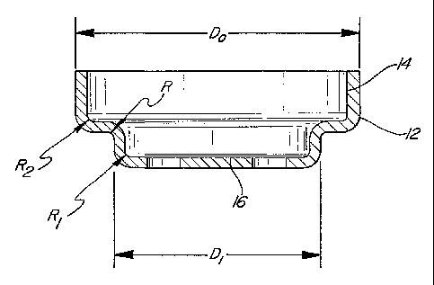
A method for cold forming splined transmission hubs is provided. A blank (10)
with an inner surface and an outer surface is secured on a tool insert support
member (100). The tool insert support member (100) has an internal spline
tooth profile (110) machined into it. A forming roller (120) is inserted
inside the blank and then moves radially under pressure until it contacts an
inner surface of the blank. A set of teeth (111) are created on the outer
surface of the blank (10) and the blank (10) is rotated relative to the
forming roller (120) to form an oil reservoir on the inner surface of the
blank.


French Abstract

La présente invention concerne un procédé de formage à froid de moyeux de transmission cannelés. Selon ce procédé, une ébauche (10) présentant une surface interne et une surface externe est fixée sur un élément de support d'insertion d'outil (100). Un profilé à dents cannelé interne (110) est usiné dans cet élément de support d'insertion d'outil (100). Un rouleau de formage (120) est inséré dans l'ébauche et se déplace radialement sous pression, jusqu'à entrer en contact avec la surface interne de l'ébauche. Un ensemble de dents (111) est pratiqué sur la surface externe de l'ébauche (10), puis l'ébauche (10) est mise en rotation par rapport aux rouleaux de formage (120), afin de produire une réserve d'huile à la surface interne de l'ébauche.

Claims

Note: Claims are shown in the official language in which they were submitted.


Claims
What is claimed is:
1. A method for cold forming a transmission hub from a cup-shaped blank having
an
outer surface and an inner surface, the method comprising the steps of:
positioning the blank axially within of a tool insert support member having a
spline tooth portion;
exerting a radial pressure on the blank forcing the blank into engagement with
the spline tooth portion thereby forming a set of teeth on the outer surface
of the
blank; and
forming an oil reservoir in the inner surface of the blank.
2. A method as claimed in claim 1 wherein said exerting step and said forming
step
occur simultaneously.
3. A method as claimed in claim 2 wherein said exerting step and said forming
step
includes rotating a forming roller relative to said blank to form said oil
reservoir and
exert said radial pressure.
4. A method as set forth in claim 3 wherein said method includes a step of
forming a
wall defining a portion of said reservoir.
5. A method as set forth in claim 4 including a step of forming a
strengthening lip
around a periphery of the blank interconnecting said set of teeth.
6. A method as set forth in claim 4 wherein said wall and strengthening lip
are
formed simultaneously with said set of teeth and said reservoir.
7. A method as set forth in claim 6 wherein said tool insert support member is
rotated
in excess of 600 RPM.
7

8. A method as set forth in claim 3 wherein said forming roller has an outer
diameter
and said blank has an outer diameter, said outer diameter of the forming
roller
is 40-60% of the outer diameter of the blank.
9. An apparatus for cold forming a transmission hub as set forth in any one of
claims 1 to 8, comprising
a tool insert support member having a spline tooth portion;
a freely rotating forming roller; and
a drive for rotating said tool insert support member relative to said forming
roller and for moving said forming roller radially and axially relative to
said tool
insert support member.
10. A method for cold forming a transmission hub from a cup-shaped blank
having
an outer surface and an inner surface, said inner surface including a bottom
surface,
the method comprising the steps of:
positioning the blank axially within of a tool insert support member having a
spline tooth portion;
inserting a forming roller into said cup-shaped blank, without the forming
roller contacting the bottom surface;
rotating the blank;
exerting a radial pressure on the blank by moving the forming roller relative
to
the rotating blank forcing the blank into engagement with the spline tooth
portion
thereby forming a set of teeth on the outer surface of the blank; and
forming an oil reservoir in the inner surface of the blank.
11. A method as claimed in claim 10 wherein said exerting step and said
forming step
occur simultaneously.
12. A method as claimed in claim 11 wherein said exerting step and said
forming step
includes rotating said forming roller relative to said blank.
8

13. A method as set forth in claim 12 wherein said forming roller has an outer
diameter and said blank has an outer diameter, said outer diameter of the
forming
roller is 40-60% of the outer diameter of the blank.
14. A method as set forth in claim 13 wherein said method includes a step of
forming
a wall defining a portion of said reservoir.
15. A method as set forth in claim 14 including a step of forming a
strengthening lip
around a periphery of the blank interconnecting said set of teeth.
16. A method as set forth in claim 14 wherein said wall and strengthening lip
are
formed simultaneously with said set of teeth and said reservoir.
17. A method as set forth in claim 16 wherein said tool insert support member
is
rotated in excess of 600 RPM.
9

Description

Note: Descriptions are shown in the official language in which they were submitted.


CA 02423855 2003-03-27
WO 02/28561 PCT/CA01/01392
COOL FORMING OF SPLINED TRANSMISSION HUBS
Field of the Invention
The invention relates to hubs for automotive transmissions. More particularly,
this invention relates to a one-step production method for cold forming a hub
of an
automotive transmission.
Description of the Related Art
Flow forming of transmission components, such as clutch housings, is a common
manufacturing process. Typically, a tubular shell is provided from a stamped
disc, and
internal drive spline teeth are roll formed while maintaining a smooth and
constant outer
diameter. In axial roll forming, a cup-shaped blank is mounted on a shaped
mandrel, and
a roll formed tool moves axially to press the metal to the tooth shape on the
mandrel,
essentially one tooth at a tune. The mandrel is rotated to present the
unworked surface to
the roll form to allow the entire inner surface to be splined. United States
Patent
5,515,955 discloses such a cold forming process to generate spline teeth in a
torque
converter. And United States Patent 5,384,949 discloses a mufti-step cold
forming
process for forming a clutch housing with an internal radial spline, a torque
transmitting
tube portion and an axially extending drive portion.
Cold forming a series of teeth in the thickened outer rim portion of a starter
ring
gear is disclosed in United States Patents 5,152,061, 5,203,223, 5,237,744 and
5,404,640. In United States Patent 5,404,640 there is an indication that where
the teeth
are totally cold formed, tight tolerances are difficult to achieve and an
additional cutting
step is required after the cold forming step is completed. This additional
step adds cost
and cycle time to the manufacturing process.
SUBSTITUTE SHEET (RULE 26)

CA 02423855 2003-03-27
WO 02/28561 PCT/CA01/01392
The existing methods are limited to housings with internal splines, or
housings with
external splines that must be subsequently machined or broached to achieve
acceptable
tolerances. An oil reservoir or dam, typically present to supply lubricant
between the spline
teeth and contacting clutch plates, is typically machined into housings in a
separate and
subsequent metal removal step.
Summary Of The Invention
The invention describes a method for cold forming a transmission hub from a
blank having an outer surface and an inner surface using a tool insert support
member
having a spline tooth portion and a reservoir portion including a forming
roller. The.
method includes the steps of positioning the blank axially with the spline
tooth portion of
the tool insert support member, engaging the spline tooth portion with the
outer surface of
the blank, exerting a radial pressure on the blank forcing the blank into
engagement with
the spline tooth portion, creating a set of teeth on the outer surface of the
blank; and rotating
the blank relative to the forming roller to form an oil reservoir on the inner
surface of the
blank.
Brief Description Of The Drawings
Advantages of the invention will be readily appreciated as the same becomes
better
understood by reference to the following detailed description when considered
in connection
with the accompanying drawings, wherein:
Figure 1 is a cross-sectional view of a steel cylindrical blank;
Figure 2 is a top view of the steel cylindrical blank;
Figure 3 is a cross-sectional view of the forming tool setup;
2

CA 02423855 2003-03-27
WO 02/28561 PCT/CA01/01392
Figure 4 is a perspective, cross-sectional view of a blank illustrating its
insertion into
a supporting tool insert having a predetermined tooth profile;
Figure 5 is a perspective, cross-sectional view according to the invention
whereby a
forming roller travels vertically and horizontally against the inside of the
blank to cold form
the material;
Figure 6 is a perspective view of the hub manufactured according to the
invention;
and
Figure 7 is a cross-sectional side view, partially cut away, of the hub of
Figure 6.
Detailed Description Of The Preferred Embodiment
As shown in Figure l, a cup-shaped blank 10 is provided having an internal
step,
defined in part by gentle radii R, Rl and Ra. The blanlc 10 has two diameters
defined by an
outer diameter Do and an inner diameter D;. The blank 10 includes an outer
surface 12 and
an inner surface 14. A bottom surface of blank 10 is indicated at 16.
The blanlc 10 is a circular disk that is mounted onto a mandrel or die and is
drawn into
the shape by well-known techniques. As shown in Figure 2, a pair of circular
holes 20 are
drilled or otherwise punched out of a bottom surface 16 of the blank 10, the
purpose of which
will be explained later. The blank 10 is preferably formed from steel, which
is capable of
being cold formed.
In the forming procedure, the blank 10 is positioned in a tool insert support
member
100, as shown in Figures 3, 4, and 5. The tool insert support member 100 is
inserted into an
opening (not shown) of a lower tool member 102. The opening of the lower tool
member
102 may be adjusted to receive tool insert support members 100 of different
sizes. Similarly,
a shaft 104 raises and lowers the lower tool member 102 to accommodate
different sized tool
insert support members 100. As a result, the same lower tool member 102 may be
used for

CA 02423855 2003-03-27
WO 02/28561 PCT/CA01/01392
cold forming blanks 10 of various shapes. The blank 10 is secured to the tool
insert support
member 100 by pins (not shown) that are inserted into the lower tool member
102 through
the circular holes 20.
The tool insert support member 100 has a spline tooth profile 110 permanently
machined into its interior. A preformed blank is created by moving a forming
roller 120 into
the interior volume of the blank 10 and abutting same on the interior surface
14. The forming
roller 120 is a component of an upper tool member 124, and is mounted in an
opening (not
shown) therein. As with the lower tool member 102, the opening of the upper
tool member
124 is sized to accommodate rollers of various sizes. Preferably, the upper
tool member 124
. and the lower tool member 102 are two pieces. However, a one-piece tooling
member may
also be used.
The outer diameter of the forming roller 120 is typically 40-60% of the outer
diameter of the blank 10. However, smaller roller diameters can be used to
maximize the
amount of cold forming per revolution.
The forming roller 120 first moves in a vertically downward direction, until
it is
positioned just above the bottom surface 16 of the blank 10. The forming
roller 120 does not
make contact with the bottom surface 16 because surface removal of material
undesirable.
Next, the forming roller 120 moves under radial pressure to force the steel
material on
the outer surface 12 of the blank 10 into a spline tooth profile 110 of the
tool insert support
member 100. The contoured shape of the forming roller 120 includes a
protrusion 125 and
recess 126. The protrusion 125 is pressed against the inner surface 14 of the
blank 10 to cold
form an oil dam or inner oil reservoir 112 on the inner surface 14 of the
blank while the
spline teeth 111 axe formed on the outer surface 12 of the blank 10. The
recess 126 allows
material to flow past the protrusion 125 to limit the width of the oil
reservoir 112 by creating
4

CA 02423855 2003-03-27
WO 02/28561 PCT/CA01/01392
a wall 113. An edge lip 127 is also provided on the forming roller 120. The
edge lip 127
forms a strengthening shoulder region 140 on the blank 10.
During the forming operation, the tool insert 100 is rotated by an electric
motor drive
or other suitable device. Rotational speeds are normally above 600 rpm,
although slower
speeds can also be used. The forming roller 120 is free running upon
contacting the blank 10
as pressure is applied. In an alternative embodiment, the forming roller 120
may also rotate.
Regardless, once the forming roller 120 contacts the rotating blank when a
force 121 is
applied thereto laterally, the fornung roller 120 forces the blank 10 into
shape.
As shown iri Figures 6 and 7, the spline teeth 111 are formed on the outer
surface 12
of the blank 10 and~the oil reservoir 112 is cold formed on the inner surface
14 of the blank
10. Because the oil reservoir 112 and the spliile teeth 111 are created at the
same time, no
further machining steps are required. In addition, a strengthening shoulder
140 that
intercomlects the spline teeth 111 is formed along the outer periphery of the
blank 10.
The invention has been described in an illustrative manner. It is to be
understood
that the terminology, which has been used, is intended to be in the nature of
words of
description rather than of limitation. Many modifications and variations of
the invention
are possible in light of the above teachings. Therefore, within the scope of
the appended
claims, the invention may be practiced other than as specifically described.

Representative Drawing
A single figure which represents the drawing illustrating the invention.
Administrative Status

2024-08-01:As part of the Next Generation Patents (NGP) transition, the Canadian Patents Database (CPD) now contains a more detailed Event History, which replicates the Event Log of our new back-office solution.

Please note that "Inactive:" events refers to events no longer in use in our new back-office solution.

For a clearer understanding of the status of the application/patent presented on this page, the site Disclaimer , as well as the definitions for Patent , Event History , Maintenance Fee  and Payment History  should be consulted.

Event History

Description Date
Time Limit for Reversal Expired 2016-10-05
Inactive: Adhoc Request Documented 2015-12-11
Letter Sent 2015-10-05
Grant by Issuance 2009-11-24
Inactive: Cover page published 2009-11-23
Inactive: Final fee received 2009-07-24
Pre-grant 2009-07-24
Notice of Allowance is Issued 2009-02-24
Letter Sent 2009-02-24
Notice of Allowance is Issued 2009-02-24
Inactive: Approved for allowance (AFA) 2009-02-17
Amendment Received - Voluntary Amendment 2008-11-12
Inactive: S.30(2) Rules - Examiner requisition 2008-06-12
Letter Sent 2006-10-10
Request for Examination Received 2006-09-21
All Requirements for Examination Determined Compliant 2006-09-21
Request for Examination Requirements Determined Compliant 2006-09-21
Letter Sent 2004-09-20
Inactive: Single transfer 2004-08-02
Inactive: Transfer information requested 2004-06-08
Correct Inventor Requirements Determined Compliant 2004-06-07
Inactive: Single transfer 2004-03-29
Amendment Received - Voluntary Amendment 2004-03-29
Inactive: IPRP received 2004-01-09
Inactive: Courtesy letter - Evidence 2003-06-03
Inactive: Cover page published 2003-06-02
Inactive: Inventor deleted 2003-05-29
Inactive: Notice - National entry - No RFE 2003-05-29
Inactive: Inventor deleted 2003-05-29
Application Received - PCT 2003-04-29
National Entry Requirements Determined Compliant 2003-03-27
Application Published (Open to Public Inspection) 2002-04-11

Abandonment History

There is no abandonment history.

Maintenance Fee

The last payment was received on 2009-08-31

Note : If the full payment has not been received on or before the date indicated, a further fee may be required which may be one of the following

  • the reinstatement fee;
  • the late payment fee; or
  • additional fee to reverse deemed expiry.

Patent fees are adjusted on the 1st of January every year. The amounts above are the current amounts if received by December 31 of the current year.
Please refer to the CIPO Patent Fees web page to see all current fee amounts.

Owners on Record

Note: Records showing the ownership history in alphabetical order.

Current Owners on Record
TESMA INTERNATIONAL INC.
Past Owners on Record
GISO CZYCHORATZKI
LUIGI RICCI
RICHARD HASTINGS-JAMES
Past Owners that do not appear in the "Owners on Record" listing will appear in other documentation within the application.
Documents

To view selected files, please enter reCAPTCHA code :


To view images, click a link in the Document Description column (Temporarily unavailable). To download the documents, select one or more checkboxes in the first column and then click the "Download Selected in PDF format (Zip Archive)" or the "Download Selected as Single PDF" button.

List of published and non-published patent-specific documents on the CPD .

If you have any difficulty accessing content, you can call the Client Service Centre at 1-866-997-1936 or send them an e-mail at CIPO Client Service Centre.

({010=All Documents, 020=As Filed, 030=As Open to Public Inspection, 040=At Issuance, 050=Examination, 060=Incoming Correspondence, 070=Miscellaneous, 080=Outgoing Correspondence, 090=Payment})


Document
Description 
Date
(yyyy-mm-dd) 
Number of pages   Size of Image (KB) 
Representative drawing 2003-03-26 1 7
Drawings 2003-03-26 4 116
Description 2003-03-26 5 213
Abstract 2003-03-26 2 62
Claims 2003-03-26 2 51
Claims 2008-11-11 3 89
Drawings 2008-11-11 4 104
Representative drawing 2009-10-27 1 8
Notice of National Entry 2003-05-28 1 189
Reminder of maintenance fee due 2003-06-08 1 106
Request for evidence or missing transfer 2004-03-29 1 101
Courtesy - Certificate of registration (related document(s)) 2004-09-19 1 129
Reminder - Request for Examination 2006-06-05 1 116
Acknowledgement of Request for Examination 2006-10-09 1 176
Commissioner's Notice - Application Found Allowable 2009-02-23 1 162
Maintenance Fee Notice 2015-11-15 1 170
PCT 2003-03-26 2 92
Correspondence 2003-05-28 1 24
PCT 2003-03-27 4 137
Correspondence 2004-06-07 1 19
Correspondence 2009-07-23 1 28
Correspondence 2015-12-29 2 117