Language selection

Search

Patent 2424166 Summary

Third-party information liability

Some of the information on this Web page has been provided by external sources. The Government of Canada is not responsible for the accuracy, reliability or currency of the information supplied by external sources. Users wishing to rely upon this information should consult directly with the source of the information. Content provided by external sources is not subject to official languages, privacy and accessibility requirements.

Claims and Abstract availability

Any discrepancies in the text and image of the Claims and Abstract are due to differing posting times. Text of the Claims and Abstract are posted:

  • At the time the application is open to public inspection;
  • At the time of issue of the patent (grant).
(12) Patent: (11) CA 2424166
(54) English Title: GAS COLLECTION PIPE CARRYING HOT GAS
(54) French Title: TUYAU DE COLLECTE DE GAZ POUR LE TRANSPORT DE GAZ A HAUTE TEMPERATURE
Status: Expired and beyond the Period of Reversal
Bibliographic Data
(51) International Patent Classification (IPC):
  • F02C 7/00 (2006.01)
  • F01D 9/02 (2006.01)
  • F01D 25/12 (2006.01)
(72) Inventors :
  • JESKE, HANS-O. (Germany)
  • MOHR, KLAUS (Germany)
(73) Owners :
  • MAN TURBOMASCHINEN AG
  • MAN TURBO AG
(71) Applicants :
  • MAN TURBOMASCHINEN AG (Germany)
  • MAN TURBO AG (Germany)
(74) Agent: BORDEN LADNER GERVAIS LLP
(74) Associate agent:
(45) Issued: 2008-09-09
(22) Filed Date: 2003-04-01
(41) Open to Public Inspection: 2004-02-23
Examination requested: 2005-01-12
Availability of licence: N/A
Dedicated to the Public: N/A
(25) Language of filing: English

Patent Cooperation Treaty (PCT): No

(30) Application Priority Data:
Application No. Country/Territory Date
102 39 534.9 (Germany) 2002-08-23

Abstracts

English Abstract


A gas collection pipe (1) carrying hot gas establishes the connection between
the
combustion chambers (9) of a gas turbine plant and the flow channel (13) of
the gas turbine. The
gas collection pipe (1) has two inlet pipe connections (2), which open via an
elbow (3) axially
into a gas ring channel (4), which is ,joined to the flow channel (13).
Cooling air is guided on the
outside along the elbow (3). A plurality of ribs (8) are arranged at spaced
locations from one
another on the outside on the gas collection pipe (1) in the area of the elbow
(3) on the side
facing away from the flow channel (13).


Claims

Note: Claims are shown in the official language in which they were submitted.

WHAT IS CLAIMED IS:
1. A gas collection pipe carrying hot gas for connection between the
combustion
chambers of a gas turbine plant and the flow channel of a gas turbine, the gas
collection pipe
comprising:
two inlet pipe connections opening axially via an elbow into a gas ring
channel joined to
the flow channel; and
a plurality of said ribs arranged at spaced locations from one another on an
outside of the
gas collection pipe in an area of said elbow on a side of the gas collection
pipe facing away from
the flow channel, wherein cooling air is led by the ribs along the elbow on
the outside of the gas
collection pipe.
2. A gas collection pipe in accordance with claim 1, wherein the ribs are led
along the
elbow beginning from a transition area into the inlet pipe connection up to
and into a middle area
of the gas ring channel on an inner side and on an outer side of the gas ring
channel.
3. A gas collection pipe in accordance with claim 1, wherein the height of the
ribs is
about 10% of a height of the gas ring channel.
4. A gas collection pipe in accordance with claim 2, wherein the height of the
ribs is
about 10% of a height of the gas ring channel.
5. A gas turbine plant arrangement comprising:
7

combustion chambers;
a gas turbine with a flow channel;
a gas collection pipe carrying hot gas between said combustion chambers and
said flow
channel and including two inlet pipe connections to the respective combustion
chambers, said
inlet pipe connections opening axially via an elbow into a gas ring channel
joined to said flow
channel; and
a plurality of said ribs arranged at spaced locations from one another on an
outside of said
gas collection pipe in an area of said elbow on a side of said gas collection
pipe facing away
from said flow channel, the ribs and the outer surface of the gas collection
pipe defining surfaces
of a cooling air channel with cooling air being led along said gas collection
pipe.
6. A gas turbine plant arrangement in accordance with claim 5, wherein said
ribs are led
along said elbow beginning from a transition area into said inlet pipe
connection up to and into a
middle area of said gas ring channel on an inner side and on an outer side of
said gas ring
channel.
7. A gas turbine plant arrangement in accordance with claim 5, wherein said
height of
said ribs is about 10% of a height of said gas ring channel.
8

Description

Note: Descriptions are shown in the official language in which they were submitted.


CA 02424166 2003-04-O1
GAS COLLECTION PIPE CARRYING HOT GAS
FIELD OF THE INVENTION
The present invention pertains to a gas collection pipe carrying hot gas for
connection
between the combustion chambers of a gas turbine plant and a flow channel of
the gas turbine.
s BACKGROUND OF THE INVENTION
A two-armed gas collection pipe of this type, also called bifurcated pipe, has
been known
from DE 198 1 s 473 Al . Due to the special shape of the inlet pipe connection
of this gas
collection pipe, the middle areas are subject to substantially higher thermal
load than the upper
area and the lower area in its outlet cross section formed by the gas ring
channel.
The gas ring channel of the gas collection pipe is cooled to the extent that
cooling air is
led along the gas ring channel on the outside. This cooling air is taken from
the compressor of
the gas turbine plant. Two ring flanges, which are provided with slots for the
passage of the
cooling air into the flow channel of the gas turbine, are provided at the
edges of the gas ring

CA 02424166 2003-04-O1
channel. In a gas collection pipe known from DE 100 32 454 A1, the cross
sections of the slots
are distributed nonuniformly over the circumference of the ring flange such
that a larger amount
of cooling air is carried along at the areas of the gas collection pipe that
are subject to a higher
thermal load than at the areas that are subject to a lower thermal load. As a
result, uniform
cooling of the gas ring channel of the gas collection pipe is achieved due to
the nonuniform
amount of cooling air.
SU1~RVIARY OF THE INVENTION
The basic object of the present invention is to design the gas collection pipe
of this type
such that the guiding of the cooling air known from DE 100 32 454 A1 is
achieved with other
means with a simultaneous intensification of the cooling.
The object is accomplished according to the present invention in a gas
collection pipe
carrying hot gas for connection between combustion chambers of a gas turbine
plant and the
flow channel of the gas turbine, wherein the gas collection pipe has two inlet
pipe connections.
The inlet pipe connections open via an elbow axially into a gas ring channel,
which is joined to
the flow channel. Cooling air is led along the elbow on the outside. A
plurality of ribs axe
arranged at spaced locations from one another on the outside on the gas
collection pipe, in the
area of the elbow, on the side facing away from the flow channel.
The ribs are placed in the gas collection pipe according to the present
invention such that
they deflect the cooling air stream directed toward the gas collection pipe
and direct it preferably
toward the middle area of the gas collection pipe, which is subject to the
highest thermal load.
Moreover, the surface of the area subject to the higher thermal load, where
better removal of heat
2

CA 02424166 2003-04-O1
is achieved, is enlarged by the ribs.
As is known from DE 100 32 454 A1, the amount of cooling air as a whole is not
increased during the cooling of the gas collection pipe. The cooling air,
which normally cools
areas that have only a low temperature load, is only led to the areas that are
subject to a higher
thermal load. As a result, the material temperature of the outlet cross
section increases in -the
cold zones. However, the temperatures drop in the two hot zones, so that a
nearly uniform
temperature profile is obtained over the circumference.
The advantages arising from the measures according to the present invention
are a
reduction of the local, service life-limiting material temperature, an evening
out of the
temperature distribution, a reduction of temperature stresses, an improvement
in the temperature
stability and corrosion resistance and an increase in the service life of the
gas collection pipe.
Another advantage is that no increased cooling air demand is necessary.
Additional
cooling air is usually sent to hot zones according to the methods known and
used hitherto to
counter temperature peaks in components exposed to high temperatures. However,
this
additional cooling air is usually not available, or it leads to a reduction in
the efficiency of the
machine.
The various features of novelty which characterize the invention are pointed
out with
particularity in the claims annexed to and forming a part of this disclosure.
For a better
understanding ofthe invention, its operating advantages and specific objects
attained by its uses,
reference is made to the accompanying drawings and descriptive matter in which
a preferred
embodiment of the invention is illustrated.
BRIEF DESCRIPTION OF THE DRAWINGS

CA 02424166 2003-04-O1
In the drawings:
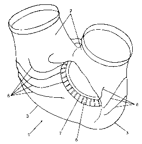
Figure 1 is a perspective view of a gas collection pipe according to the
present invention
when viewed obliquely from the top from the oncoming flow side,
Figure 2 is a perspective view of a gas collection pipe according to the
present invention
when viewed from the oncoming flow side,
Figure 3 is a perspective view of a gas collection pipe according to the
present invention
when viewed obliquely from the side, and
Figure 4 is a detail from a gas turbine plant as a half section through the
transition between
the compressor part and the turbine part of the gas turbine plant.
DESCRIPTION OF THE PREFERRED EMBODIMENT
Referring to the drawings in particular, Figure 4 shows a gas turbine plant to
the extent as
necessary for the understanding of the present invention. The gas turbine
plant is known per se
and comprises a compressor, a gas turbine and, in this case, two outer
combustion chambers 9 in
a V-shaped arrangement. Only one of the combustion chambers 9 can be
recognized in the view
in Figure 4~ The gas turbine contains a rotor disk 10, which carries rotor
blades 12, which axe
located within the ring-shaped flow channel 13 of the gas turbine. The flow
channel 13 is joined
by a gas ring channel 4 acting as a gas collection space. Only the compressor
blading 11 of the
compressor rotor can be recognized from the compressor of the gas turbine
plant in Figure 4.
The connection between the two combustion chambers 9 of the gas turbine plant
and the
flow channel 13 of the gas turbine is established via a two-armed gas
collection pipe 1 carrying
hot gas, which is shown in greater detail in Figures 1 through 3. The gas
collection pipe 1 is
4

CA 02424166 2003-04-O1
provided with two inlet pipe connections 2, which are connected each to the
gas outlet of one of
the combustion chambers 9. The inlet pipe connections 2 open via a 90E elbow 3
into a gas ring
channel 4 used as a gas collection space in the lower part of the gas
collection pipe 1. The gas
collection pipe I is provided with an outer ring flange 5 and an inner ring
flange 6, which are
joined to corresponding opposing flanges of the housing of the gas turbine.
The compressed hot
gas flows from the combustion chambers 9 through the inlet pipe connections 2
of the gas
collection pipe 1 and is united and collected in the gas ring channel 4 before
it flows into the
flow channel 13 and sets the turbine rotor 10 with the rotor blades 12 into
rotation.
Due to the design of the inlet pipe connections 2, the gas ring channel 4 of
the gas
collection pipe 1 is subjected to nonuniform thermal load by the hot gas being
carried. The
middle areas, which correspond to the 3 o'clock and 9 o'clock positions, are
subject to a higher
load than the upper and lower areas of the gas ring channel 4 corresponding to
the 6 o'clock and
l2 o'clock positions.
The entire gas collection pipe 1 is cooled by convection on the outside by
compressor air,
which is taken from the compressor of the gas turbine plant. This cooling air
is led on the
outside along the elbow 3 and, adjoining it, along the gas ring channel 4.
Slots 7 or other
openings are provided for this purpose in the outer and inner ring flanges 5,
6, which protrude as
rings into the path of flow of the cooling air. The cooling air flows
offthrough these slots 7.
The driving force for the flow of the cooling air is a pressure difference,
which builds up on both
sides of the slotted ring flanges S, 6.
To guide the cooling air, a plurality of ribs 8 are arranged at spaced
locations from one
another, e.g., by spot welding, on the gas collection pipe 1 on the outside in
the area of the elbow

CA 02424166 2003-04-O1
3 on the side facing away from the inlet flange of the gas turbine. These ribs
8 are led into the
inlet pipe connection 2 up to and into the middle area of the gas ring channel
4 along the elbow 3
beginning from the transition area both on the inner side and on the outer
side of the gas ring
channel. The ribs 8 thus arranged guide the cooling air, which arrives in a
more or less directed
manner, to the hottest areas of the gas collection pipe 1 in order to cool
these especially strongly.
At the same time, the surface to be cooled is enlarged by the ribs, as a
result of which the cooling
is further intensified.
The ribs 8 extend in the radial direction over the area near the wall. The
height of the ribs
8 depends on the size of the gas turbine. If the height of the gas ring
channel 4 is about IO mm,
the height of the ribs 8 is about 5 mm to 10 mm.
While a specific embodiment of the invention has been shown and described in
detail to
illustrate the application of the principles of the invention, it will be
understood that the :invention
may be embodied otherwise without departing from such principles.
6

Representative Drawing
A single figure which represents the drawing illustrating the invention.
Administrative Status

2024-08-01:As part of the Next Generation Patents (NGP) transition, the Canadian Patents Database (CPD) now contains a more detailed Event History, which replicates the Event Log of our new back-office solution.

Please note that "Inactive:" events refers to events no longer in use in our new back-office solution.

For a clearer understanding of the status of the application/patent presented on this page, the site Disclaimer , as well as the definitions for Patent , Event History , Maintenance Fee  and Payment History  should be consulted.

Event History

Description Date
Time Limit for Reversal Expired 2011-04-01
Letter Sent 2010-04-01
Grant by Issuance 2008-09-09
Inactive: Cover page published 2008-09-08
Inactive: Final fee received 2008-06-23
Pre-grant 2008-06-23
Notice of Allowance is Issued 2008-04-16
Letter Sent 2008-04-16
Notice of Allowance is Issued 2008-04-16
Inactive: Approved for allowance (AFA) 2008-02-03
Amendment Received - Voluntary Amendment 2007-08-27
Inactive: S.30(2) Rules - Examiner requisition 2007-06-11
Inactive: IPC from MCD 2006-03-12
Letter Sent 2005-03-17
Letter Sent 2005-03-15
Amendment Received - Voluntary Amendment 2005-02-08
Request for Examination Requirements Determined Compliant 2005-01-12
All Requirements for Examination Determined Compliant 2005-01-12
Request for Examination Received 2005-01-12
Application Published (Open to Public Inspection) 2004-02-23
Inactive: Cover page published 2004-02-22
Inactive: First IPC assigned 2003-05-29
Inactive: Applicant deleted 2003-05-02
Application Received - Regular National 2003-05-01
Filing Requirements Determined Compliant 2003-05-01
Letter Sent 2003-05-01
Inactive: Filing certificate - No RFE (English) 2003-05-01
Inactive: Correspondence - Formalities 2003-04-03

Abandonment History

There is no abandonment history.

Maintenance Fee

The last payment was received on 2008-03-27

Note : If the full payment has not been received on or before the date indicated, a further fee may be required which may be one of the following

  • the reinstatement fee;
  • the late payment fee; or
  • additional fee to reverse deemed expiry.

Please refer to the CIPO Patent Fees web page to see all current fee amounts.

Owners on Record

Note: Records showing the ownership history in alphabetical order.

Current Owners on Record
MAN TURBOMASCHINEN AG
MAN TURBO AG
Past Owners on Record
HANS-O. JESKE
KLAUS MOHR
Past Owners that do not appear in the "Owners on Record" listing will appear in other documentation within the application.
Documents

To view selected files, please enter reCAPTCHA code :


To view images, click a link in the Document Description column. To download the documents, select one or more checkboxes in the first column and then click the "Download Selected in PDF format (Zip Archive)" or the "Download Selected as Single PDF" button.

List of published and non-published patent-specific documents on the CPD .

If you have any difficulty accessing content, you can call the Client Service Centre at 1-866-997-1936 or send them an e-mail at CIPO Client Service Centre.


Document
Description 
Date
(yyyy-mm-dd) 
Number of pages   Size of Image (KB) 
Description 2003-04-01 6 228
Abstract 2003-04-01 1 17
Claims 2003-04-01 2 58
Cover Page 2004-01-30 1 28
Drawings 2007-08-27 4 106
Representative drawing 2008-06-03 1 9
Cover Page 2008-08-26 2 41
Courtesy - Certificate of registration (related document(s)) 2003-05-01 1 107
Filing Certificate (English) 2003-05-01 1 159
Reminder of maintenance fee due 2004-12-02 1 110
Acknowledgement of Request for Examination 2005-03-17 1 178
Commissioner's Notice - Application Found Allowable 2008-04-16 1 164
Maintenance Fee Notice 2010-05-13 1 170
Correspondence 2003-04-03 3 73
Correspondence 2008-06-23 1 33