Note: Descriptions are shown in the official language in which they were submitted.
CA 02424227 2003-04-02
SWIMMING GOGGLES
lr'ield of the invention
[00011 The present invention relates to a pair of swimming goggles for
swimming pool purposes, more particularly, a pair of swimming goggles
with an improved strap head structure for providing a comfort wearing, and
avoiding the seepage of water and an overly deflection of the swimming
goggles in use.
Description of the Related Art
[0002) The head strap of the swiinmuig goggles includes single thread
type, double thread type, or a type of folding a single thread to function
like
double threads. Whatever the type is, the head strap of a prior art is
disposed at a central position of the outer side of the lens frame. However,
the area around the upper and lower positions of the eye holes and the nose
bridge of a person is significantly unsmooth. When the swimming goggles
are sleeved on the head and fixed, the head strap intendedly provides an
equal pull force on the upper and low positions of the eye holes. However,
when the lens frame is matched to the eye hole, the actual effect of the pull
force is not desired. In otlier words, the unsmooth area at the upper and
lower position of the eye holes causes deflection of the lens frames wlien
the head strap is pulled in use. Therefore, such a deflection causes an
i
CA 02424227 2003-04-02
undesired refraction cffect of the lenses in water.
[0003] Moreover, a straightforward distance between an upper position of
the eye hole and a back part of the head is larger than a straightforward
distance between a lower position of the eye hole and a back part of the
head. Thus, an upper edge of the lens frame is overly matched with the
upper position of the eye hole such that the seepage of water would
possibly occur at a lower position of the eye hole. For the swimming
goggles which is a double thread type or a type of folding a single thread to
function like double threads, a wearer usually downwardly pull the lower
head strap thereby lerigthening the head strap for overcoming above
mentioned drawback. However, only by pulling the lower head strap, a
corresponding downward slippage of the upper head strap may occur
thereby causing unreliable wearing of the swimming goggles. Therefore, a
wear commonly pull the upper head strap downwardly and pull the lower
head strap upwardly tliereby balancing the upward and downward pull
forces. However, such a pulling method causes overly pull force applied on
the upper position of the eye holes resulting in a discomfort of the wearer.
For a single thread type swimming goggles in use, a wearer commonly
upwardly pulls the head strap thereby lengtliening an application length
relative to the lower position of the eye holes resulting in a same
discomfort feeling for the wearer.
2
CA 02424227 2003-04-02
SUMMARY OF THE INVENTION
[0004] Accordingly, the primary object of the present invention is to
provide a pair of swimming goggles in which the straightforward distances
between the upper and lower positions of the eye holes and the back part of
the head can be properly adjusted thereby providing the proper pull force
when wearing and providing the upper and lower edges of the lens frames
to properly and comfortably contact the upper and lower positions of the
eye holes.
[0005] A second object of the present invention is that, a pair of head
straps is adopted to properly pull the upper and lower edges of the lens
frames thereby preventing a deflection of the lens frames in use resulting
from an overly pull force thereby providing an desired refraction effect of
the lenses in water.
[0006] The main feature of the swimming goggles of the present
invention is that the head strap means of the swimming goggles at least
includes a first thread, a second thread, and an adjustment fastener disposed
at the first and second threads. The first thread is disposed at an upper
position of the outer sides of the left and right lens frames and the second
thread is disposed at a lower position of the outer sides of the left and
right
lens frames thereby providing adjustment of the different application
lengths for the first and second threads.
3
CA 02424227 2007-05-30
BRIEF DESCRIPTION OF THEDRAWINGS
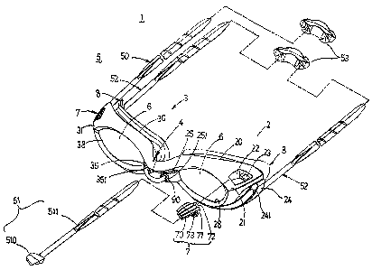
[0007] FIG. 1 is a perspective view of a pair of swimming goggles of the
first embodiment of the present invention with a partial exploded view
thereof.
[0008] FIG. 2 is perspective view of a pair of swimming goggles of the
FIG. 1 with the second thread assembled.
[0009] FIG. 3 is a front view of the lens fraines, the bridge member and
the gasket witll an integral structure.
[00010] FIG. 4 is a cross-sectional view of the FIG. 3 taken from 4-4.
[000111 FIG. 5 a lateral view of the swimming goggles wherein a head
strap is adjusted in tlie midst of the bridge member.
[00012] FIG. 6 is a perspective view of a second embodiment of the
present invention.
[00013] FIG. 7 is a perspective view of a tllird einbodiment of the present
invention.
DETAILED DESCRIPTION OF THE PREFERRED EMBODIMENTS
[00014] Referring to FIGS.l and 2, a pair of swimming goggles of the
present invention comprises a left lens frame 2, a right lens frame 3, a
bridge member 4, and a head strap means 5. The left and right lens frames
2, 3 respectively include inner surfaces 20, 30 and outer surface 21, 31,
wherein a pair of receiving grooves 28, 38 is respectively defined betweeii
4
CA 02424227 2003-04-02
the inner surfaces 20, 30 and the outer surfaces 21, 31 for retaining a pair
of
lenses 6. A pair of gaskets 8 is integrally formed on the inner surfaces 20,
30 of the left and right lens frames 2, 3, respectively, for providing comfort
contact with the eye holes of a wearer. Also referring to F1GS.1 and 3, an
identical structure is disposed on the lateral sides of the left and right
lens
frames 2, 3. A recess 22 is defined on the outer side of the left lens fra.me
2.
The right lens frame 3 also defines a recess 32. A pair of elongated round
assembly holes 23, 33 is defined within the recesses 22, 32, respectively.
[00015] A pair of rigid bodies 7 is assembled into the recesses 22, 32.
The rigid body 7 includes a long protrusion 70 and a short protrusion 71.
One side of the long protrusion 70 is adjacent to the short protrusion 71.
The cross section of a pair of protrusions 70, 71 is L-shaped. The long
protrusions 70 are properly assembled to the recesses 22, 32 and properly
mantle the recesses 22, 32. The short protrusions 71 properly engage with
inner sides of the recesses 23, 33 in which the assembly holes 23, 33 are
defined. A strengthening protrusion 72 extending from the short protrusion
71 has an identical shape of structure corresponding to that of the assembly
holes 23, 33. A passageway 73 defined in the strengthening protrusion 72 is
in communication with each of the assembly holes 23, 33 for allowing a
first and second threads 50, 51 to pass therethrough. Thus, the
strengthening protrusions 72 are assembled into the assembly holes 23, 33
thereby strengthening the structures of the assembly holes 23, 33 and
CA 02424227 2003-04-02
enhancing the rigidness of the recesses 23, 33 when wearing the swimming
goggles.
(000161 Additionally, a pair of first joint members 24, 34 formed at the
lower positions of the recesses 22, 32 defines a pair of second holes 241,
341 for allowing a third thread 52 of the head strap means 5 to pass
therethrough (detailed description later). A pair of second joint members 25,
35 is formed at the inner sides of the left and right lens frames 2, 3 and
adjacent to the central position between the left and right lens frames 2, 3.
A pair of adjustment holes 251, 351 is respectively defined in the second
joint members 25, 35. A sleeve member 90 defining a passageway
therethrough in communication with the environment at lateral ends thereof
is assembled into each of the adjustment holes 251, 351 thereby
strengthening the structure of the adjustment holes 251, 351 and facilitating
the threads of the head strap means 5 to pass therethrough. Also referring to
FIGS. 3 and 5, a pair of coupling grooves 29, 39 is respectively defined at
the lower edges of the left and right lens frames 2, 3 and is reserved a
certain distance from the first joint member 24. The third thread 52 of the
head strap means 5 extends around the first joint members 24, 34 and the
coupling grooves 29, 39, then is secured within the certain spaces between
the coupling grooves 29, 39 and the second joint members 24, 34.
Afterwards, the third tliread 52 is pulled straightforwardly for facilitating
balancing the swimming goggles in use. The bridge member 4 is integrally
6
CA 02424227 2003-04-02
formed at the upper edges of the inner sides of the left and right lens frames
2, 3 and is adjacent to the top of the second joint members 25, 35.
[00017J Referring to FIG. I again, the head strap means 5 includes the
first thread 50, the second thread 51, the third thread 52, and a pair of
adjustment fasteners 53. The first and second threads 50, 51 with the same
structure are assembled into the assembly holes 23, 33, respectively. For
better illustration, the second thread 51 is separated from the swimming
goggles. As shown in FIG. 1, the second thread 51 includes a coupling end
510 and a free end 511. The coupling end 5-10 having a structure
corresponding to that of the recess 22 of the aforementioned left lens frame
2 extends through the passageway 73 of the L-shaped rigid body 7, then is
assembled into the recess 22 to fill up the recess 22. The upper surface of
the long protrusion 70 of the L-shaped rigid body 7 is coplanar with the
upper opening plane of the recess 22. One section of the coupling end 510
of the second thread 51 has a round structure and the other section of the
free end 511 of the second thread 51 has a flat structure thereby facilitating
the insertion of the thread through the passageway 73 of the L-shaped rigid
body 7 in assembly. The tliird thread 52 shown as the broken lines in FIG. 5
extends through firstly the second hole 341 of the right lens frame 3,
secondly the adjustment holes 351, 251 of the joint members 35, 25, and
tllirdly the second hole 241 of the left lens frame 2, and is secured by the
certain spaces between the coupling grooves 29, 39 and the first joint
7
CA 02424227 2003-04-02
members 24, 34. It is noted that referring to FIG. 4 wliich is a lateral view
of the present invention, the assembly holes 23 and the second holes 241
are respectively disposed at each side of the horizontal central line X of the
hole 251 of the second joint member 25, i.e. at each side of the horizontal
central line of the left and right lens frame 2, 3 thereby facilitating
balancing the pull force of the first and second threads 50, 51 when in use.
[00018] The adjustment fasteners 53 are disposed at the first, second
threads 50, 51 and third thread 52 for adjusting the length of the threads. It
is noted that the part of the third thread 52 disposed within the bridge
member 4 can be adjusted according to the height of the nose bridge of a
wearer. Shown as the broken lines of FIG. 5, by pulling the third thread 52,
the wearer can adjust the third thread 52 according to the height of his own
nose bridge. After adjustment, a part of the third thread 52 disposed
adjacent to the second joint members 25, 35 is secured by the certain
spaces between the coupling grooves 29, 39 and the first jo}nt members 24,
34. Thus, when by pulling the head strap, the swimming goggles are
sleeved on the head and fixed, the first joint members 24, 34 bear the pull
force such that the above mentioned part of the tliird thread 52 would not
be affected and the undesired deformation of the lens frames is avoided.
Additionally, a straightforward distance between a lower position of the eye
holes and a back part of the head of is relatively short. By adjusting the
adjustment fastener 53 the application length of the third thread 52 is
8
CA 02424227 2003-04-02
adjusted. A straightforward distance between an upper position of the eye
holes and a back part of the head is relatively long. By adjusting another
adjustment fastener 53 the application length of the first and second threads
50, 51 is adjusted. Therefore, a proper pull force is provided for wearing
the swimming goggles such that the upper and lower edges of the left and
the right lens frames 2, 3 are adjusted to comfortably match the periphery
of the wearer's eye holes. Since the upper and lower edges of the lens
frames are pulled by a pair of the head straps, u deflection of the lens
frames due to an overly pull force in use is prevented thereby providing a
desired refraction effect of the lenses 6 in water.
[00019] Also referring to FIGS. 6 and 7 in which the swimming goggles
1', 1" of a second and third embodiments of the present invention are
shown, the second and third embodiments have the same main structure
with the first embodiment. The difference therebetween lies in .that the
swimming goggles 1' of the second embodiment shown in FIG. 6 have not
a second joint member and include a third hole 26' and a fastening member
27'. The inner sides of the left and right lens frames 2', 3' are only
integrally interconnected by a bridge member 4'. The first and second
threads 50', 51' respectively extend through the second holes 241' disposed
at the outer sides of the left and right lens frames 2', 3' (the second hole
of
the right lens frame 3' is not sliown). The tllird thread 52' includes a pair
of
sections. One end of each the section has a round shaped -and the other end
9
CA 02424227 2003-04-02
of the section lias a flat shaped for facilitating the insertion of the third
thread 52' tlirough the third holes 26' of the left and right lens frames 2,
3',
and the fastening members 27' in assembly. The round shaped free end
thereof extends through the third hole 26', and then is secured by the
corresponding fastening member 27'. The purposes for adjustment of the
first, second and third threads 50', 51', and 52' by respectively adjusting a
pair of adjustment fasteners 53 are equally achieved.
[00020] The swimming goggles 1" of the third embodiment shown in
FIG. 7 are featured in the arrangement of the bridge member 4". The bridge
member 4" includes an adjustment fastener 40" which interconnects a pair
of joint holes 26", 36" -defined at the inner sides of the left and right lens
frames 2", 3". The outer sides of the left and right lens frames 2", 3" define
a pair of recesses as shown in the first embodiment for being assembled
with the first and second threads 50", 51". The first and second threads 50",
51" are assembled with the rigid bodies 7". Therefore; the purposes for
respective adjustment of the first and second threads 50", 51" and
providing the swimming goggles of the present invention a proper and
comfort contact witli the eye holes are equally achieved.
[00021) Although the invention has been explained in relation to its
preferred embodiments, it is to be understood that many other possible
modifications and variations can be made without departing from the spirit
and scope of the invention as hereinafter claimed.