Note: Descriptions are shown in the official language in which they were submitted.
CA 02424344 2003-04-02
LANDING GEAR AND METHOD OF ASSEMBLY
Background of the Invention
This invention relates generally to landing gear used in the support of
semitrailers
and more particularly to gearing configurations of a landing gear.
Landing gear of the present invention has particular application in the
support of
semitrailers when they are not attached to a tractor. The landing gear
conventionally
includes a pair of telescoping legs capable of extending to engage the
pavement or other
supporting surface to hold up the front end of the semitrailer, and of
retracting to move up
out of the way when the semitrailer is being pulled over the road by a
tractor. The extension
and retraction is most often carried out by the driver manually turning a
crank connected by
gearing to a lead screw in the leg. The lead screw interconnects telescoping
leg sections of
the leg so as to retract a lower leg section into an upper leg section or
extend the lower leg
section from the upper leg section depending on the direction the screw is
rotated.
The semitrailers are very large and heavy by themselves, and further carry
large
loads. In order to lift such loads when extending the legs, the gearing
provides a mechanical
advantage in addition to the crank. In providing the mechanical advantage, the
rotation of
the lead screw is very much retarded in relation to the rotation of the crank.
In other words,
it will require numerous turns of the crank to achieve a very small linear
travel of the lower
leg section relative to the upper leg section. The high ratio of turns per
inch of travel is
acceptable when the legs are actually bearing the load of the trailer because
of the
accompanying mechanical advantage. Once the load is relieved from the leg,
such as when
the semitrailer is supported by the tractor, the slow linear movement of the
lower leg section
becomes an issue because of the long time it takes to get the lower leg
section retracted Far
enough above the ground for safe travel over the road. Likewise, slow
extension of the
lower leg section into engagement with the pavement is also highly
undesirable. It is known
to provide for shifting between a low gear and a high gear in the gearing,
with the low gear
providing the mechanical advantage needed for lifting large loads and high
gear providing
for more rapid linear movement of the lower leg section (i.e., a lower turns
per inch ratio).
Co-assigned U.S. Patent No. 4,187,733 discloses gearing of this type.
Generally, a large
difference between the turns per inch ratio in low gear versus high gear is
desirable.
1
CA 02424344 2010-03-29
67405-13
One way to assist in providing greater lift in low gear is to provide a gear
on an idler
shaft located between the input shaft (of the crank) and the output shaft
connected to the lead
screw. This arrangement is typically referred to as a double reduction. An
idler shaft
requires additional space in the gear box, which is at a premium. In addition,
there are two
additional openings in the gearbox containing bearings for the idler shaft.
These openings
provide an additional place from which leakage of lubricant becomes more
likely over the
life of the landing gear.
Conventionally, the gearing has been located in a gear box which is formed
separately from the leg. For instance, the gear box may be formed from two
halves which
are individually stamped and later bolted together. The gears making up the
gearing may
be installed in one half of the gear box before it is completed. The gear box
is welded or
otherwise attached to the landing gear leg on the inside or outside of the
leg. The input shaft
from the crank, and the output shaft which is connected to the lead screw, are
held by
bearings located in the landing gear leg. The conventional construction
requires a number
of parts in addition to the landing gear leg and several manufacturing steps
to assemble the
gearing in the gear box with the input and output shafts and the leg. It is
known to
incorporate some of the gearing in the leg, but significant manufacturing
steps are required
to assemble component parts of the gearing together with the input and output
shafts.
Summary of the Invention
Among the several aspects and features of the present invention may be noted
the
provision of landing gear which is of simplified construction; the provision
of such landing
gear having a compact gear arrangement; the provision of such landing gear
which provides
additional torque in low gear and augmentation of crank rotation in high gear
to increase
speed; the provision of such a landing gear which inhibits leakage of
lubricant; the provision
of such landing gear which has fewer external bearings receiving shafts; the
provision of
such landing gear which has fewer parts; the provision of such landing gear
which is lighter
in weight; and the provision of such landing gear which can be efficiently
assembled.
Further among the several aspects and features of the present invention may be
noted
the provision of a method of assembling landing gear which can be carried out
rapidly and
with precision; th provision of such a method which reduces the number of
externally
exposed shaft bearings to minimize leakage; and the provision of such a method
which
reduces the number of steps to complete manufacture of the landing gear.
In general, one embodiment of the invention is directed to landing gear for
selectively supporting a semitrailer. The landing gear includes a leg having
an upper section
and a lower section in telescoping arrangement with each other and a lead
screw mounted
2
CA 02424344 2010-03-29
67405-13
for extending and retracting the upper and lower sections relative to each
other upon rotation
of the lead screw. The landing gear also includes an input shaft for applying
a torque to the
lead screw to drive rotation thereof, the input shaft being rotatable about a
first rotation axis
and movable in translation along the first rotation axis for shifting between
a first position
for low gear operation and a second position for high gear operation. The
landing gear also
includes an output shaft including an output gear for transmitting torque to
the lead screw,
the output shaft being mounted for rotation about a second rotation axis and
being generally
axially aligned with the input shaft. The landing gear also includes a gearing
subassembly
configured so that for each rotation of the input shaft, the output shaft
rotates less than one
rotation for low gear operation and interconnecting the generally axially
aligned input and
output shafts in the second position so that for each rotation of the input
shaft, the output
shaft rotates more than one rotation, whereby the gearing subassembly augments
lift when
the input shaft is in the first position and augments speed in the second
position.
Another embodiment of the invention is directed to landing gear for
selectively
supporting a semitrailer. The landing gear includes a leg having an upper
section and a
lower section in telescoping arrangement with each other. The upper section
has opposing
walls, a first of the walls having a slot therein at an upper end. The landing
gear also
includes a lead screw mounted for extending and retracting the upper and lower
sections
relative to each other upon rotation of the lead screw and an input shaft
rotatable about a first
rotation axis and connected in operation to the lead screw for driving
rotation thereof. The
input shaft extends into the upper section of the leg through the slot in the
first wall. The
landing gear further includes a cover plate attached to the upper section
generally over the
slot, the cover plate including a bearing receiving the input shaft there
through.
Another embodiment of the invention is directed to a method of assembling a
landing gear leg. The method includes the steps of mounting at least one shaft
on a bearing
located in a bearing member and inserting the bearing member mounting the
shaft into an
upper section of the landing gear leg.
Another embodiment of the invention is directed to a subassembly for use in
manufacturing a landing gear leg. The subassembly includes a bearing member
adapted to
be mounted on the leg in an open top thereof and a shaft mounted on the
bearing member
for rotation. The subassembly also includes gearing associated with the shaft
for use in
transmitting rotation, whereby the shaft and gearing are supported for
rotation independently
of mounting in the leg.
3
CA 02424344 2010-03-29
67405-13
Another embodiment of the invention is directed to landing gear for
selectively supporting a semitrailer, the landing gear comprising: a leg
having an
upper section and a lower section in telescoping arrangement with each other;
a
lead screw mounted for extending and retracting the upper and lower sections
relative to each other upon rotation of the lead screw; an input shaft for
applying a
torque to the lead screw to drive rotation thereof, the input shaft being
rotatable
about a first rotation axis and movable in translation along the first
rotation axis for
shifting between a first position for low gear operation and a second position
for
high gear operation; an output shaft including an output gear for transmitting
torque to the lead screw, the output shaft being mounted for rotation about a
second rotation axis and being generally axially aligned with the input shaft;
and a
gearing subassembly configured so that for each rotation of the input shaft,
the
output shaft rotates less than one rotation for low gear operation and
interconnecting the generally axially aligned input and output shafts in the
second
position so that for each rotation of the input shaft, the output shaft
rotates more
than one rotation whereby the gearing subassembly augments lift when the input
shaft is in the first position and augments speed in the second position;
wherein
the gearing subassembly comprises at least two gears mounted for rotation
about
axes spaced from the axis of rotation of the input and output shafts, a first
of the
two gears being in driving engagement with the input shaft in the first
position
thereof, and a second of the two gears being in driving engagement with the
input
shaft in the second position thereof, the gearing subassembly comprises at
least
one idler shaft, and the gearing subassembly further comprises a third gear
engaged with the output shaft, the first, second and third gears being mounted
for
conjoint rotation on the idler shaft.
Another embodiment of the invention is directed to landing gear for
selectively supporting a semitrailer, the landing gear comprising: a leg
having an
upper section and a lower section in telescoping arrangement with each other;
a
lead screw mounted for extending and retracting the upper and lower sections
relative to each other upon rotation of the lead screw; an input shaft for
applying a
3a
CA 02424344 2010-03-29
67405-13
torque to the lead screw to drive rotation thereof, the input shaft being
rotatable
about a first rotation axis and movable in translation along the first
rotation axis for
shifting between a first position for low gear operation and a second position
for
high gear operation; an output shaft including an output gear for transmitting
torque to the lead screw, the output shaft being mounted for rotation about a
second rotation axis and being generally axially aligned with the input shaft;
and a
gearing subassembly configured so that for each rotation of the input shaft,
the
output shaft rotates less than one rotation for low gear operation and
interconnecting the generally axially aligned input and output shafts in the
second
position so that for each rotation of the input shaft, the output shaft
rotates more
than one rotation whereby the gearing subassembly augments lift when the input
shaft is in the first position and augments speed in the second position;
wherein
the gearing subassembly comprises at least two gears mounted for rotation
about
axes spaced from the axis of rotation of the input and output shafts, a first
of the
two gears being in driving engagement with the input shaft in the first
position
thereof, and a second of the two gears being in driving engagement with the
input
shaft in the second position thereof, the gearing subassembly comprises at
least
one idler shaft, and wherein the gearing subassembly further comprises third
and
fourth gears and first and second idler shafts, the first and third gears
being
mounted on the first idler shaft and the second and fourth idler gears being
mounted on the second idler shaft.
Another embodiment of the invention is directed to landing gear for
selectively supporting a semitrailer, the landing gear comprising: a leg
having an
upper section and a lower section in telescoping arrangement with each other;
a
lead screw mounted for extending and retracting the upper and lower sections
relative to each other upon rotation of the lead screw; an input shaft for
applying a
torque to the lead screw to drive rotation thereof, the input shaft being
rotatable
about a first rotation axis and movable in translation along the first
rotation axis for
shifting between a first position for low gear operation and a second position
for
high gear operation; an output shaft including an output gear for transmitting
3b
CA 02424344 2010-03-29
67405-13
torque to the lead screw, the output shaft being mounted for rotation about a
second rotation axis and being generally axially aligned with the input shaft;
and a
gearing subassembly configured so that for each rotation of the input shaft,
the
output shaft rotates less than one rotation for low gear operation and
interconnecting the generally axially aligned input and output shafts in the
second
position so that for each rotation of the input shaft, the output shaft
rotates more
than one rotation whereby the gearing subassembly augments lift when the input
shaft is in the first position and augments speed in the second position;
wherein
the gearing subassembly comprises at least two gears mounted for rotation
about
axes spaced from the axis of rotation of the input and output shafts, a first
of the
two gears being in driving engagement with the input shaft in the first
position
thereof, and a second of the two gears being in driving engagement with the
input
shaft in the second position thereof, the gearing subassembly comprises at
least
one idler shaft, and further comprising: a top cover received within an open
upper
end of the upper section of the leg and closing the open upper end, wherein
the
gearing subassembly is supported by the top cover such that the gearing
subassembly is located substantially within the upper section of the leg.
3c
CA 02424344 2003-04-02
Brief Description of the Drawings
FIG. 1 is a side elevation of a semitrailer unhitched from its truck tractor,
and having
landing gear thereon supporting the front end of the semitrailer;
FIG. 2 is an enlarged perspective view of a landing gear leg of the landing
gear
depicted in Fig. 1;
FIG. 3 is a front side elevation of the landing gear leg of Fig. 2;
FIG. 4 is a right side elevation of the landing gear leg of Fig. 2;
FIG. 5 is an exploded perspective view of the landing gear leg of Fig. 2
capable of
receiving a gearing subassembly for both conventional and reverse mounted
legs;
FIG. 6 is a side elevation of a mounting plate of the landing gear leg of Fig.
2;
FIG. 7 is a side elevation of an upper portion of the landing gear leg;
FIG. 8 is a plan view of an upper section of the landing gear leg;
FIG. 9 is a bottom side perspective of a top cover and associated idler shaft
and
gearing of a single idler landing gear leg according to one embodiment of the
invention;
FIG. 10 is an inverted view of the top cover and idler shaft of Fig. 9 with
the parts
exploded to illustrate assembly;
FIG. 11 is a schematic fragmentary cross section of the single idler landing
gear leg
of Fig. 9 with the input shaft in the low gear position;
FIG. 12 is a schematic fragmentary cross section of the single idler landing
gear leg
of Fig. 9 with the input shaft in the high gear position;
FIG. 13A is an end view of the idler shaft of the single idler landing gear of
Fig. 9;
FIG. 13B is a sectional view of the idler shaft taken along line 13B-13B of
Fig. 13A;
FIG. 14 is a bottom side perspective of a top cover of the single idler
landing gear
leg;
FIG. 15 is an inverted perspective view of the top cover of Fig. 14 with the
parts
exploded to illustrate assembly;
FIG. 16 is a schematic, fragmentary cross section of another version of the
single
idler landing gear leg having an idler shaft supported from the side
internally of the leg;
FIG. 17 is a bottom side perspective of a top cover and associated dual idler
shafts
and gearing according to one embodiment of the invention;
FIG. 18 is an inverted perspective view of the top cover and dual idler shafts
of FIG.
17 with the parts exploded to illustrate assembly;
FIG. 19 is a schematic, fragmentary side elevation of a dual idler landing
gear leg
with a wall of the leg and other selected parts broken away to reveal
construction with the
input shaft in the high gear position;
4
CA 02424344 2003-04-02
FIG. 20 is a schematic, fragmentary side elevation of a dual idler landing
gear leg
with a wall of the leg and other selected parts broken away to reveal
construction with the
input shaft in the low gear position;
FIG. 21 is an enlarged fragmentary side elevation of the dual idler landing
gear;
FIG. 22A is an end view of the low idler shaft of the dual idler landing gear;
FIG. 22B is a sectional view of the low idler shaft taken along line 22B-22B
of Fig
22A;
FIG. 23A is an end view of the high idler shaft of the dual idler landing
gear;
FIG. 23B is a sectional view of the high idler shaft taken along line 23B-23B
of Fig
23A;
FIG. 24 is a bottom side perspective of the top cover of the dual idler
landing gear
leg;
FIG. 25 is an exploded perspective of the top cover of :Fig. 24;
FIG. 26 is a fragmentary front elevation of a single idler landing gear leg
having
components substantially identical to the dual idler landing gear leg of Figs.
20 and 21; and
FIG. 27 is a fragmentary side elevation of the single idler landing gear leg
with a wall
of the leg and other selected parts broken away to reveal construction.
Corresponding reference characters indicate corresponding parts throughout the
several views of the drawings.
Detailed Description of the Preferred Embodiments
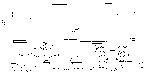
Figure 1 illustrates landing gear, indicated generally at 10, for the support
of
semitrailers when not attached to a tractor. The landing gear 10 typically
includes a pair of
legs 11 (only one leg is shown) located near respective front corners of a
semitrailer 12.
Each leg 11 is capable of extending to engage the pavement S or other
supporting surface
to hold up the front end of the semitrailer as is well understood in the art.
A shoe 14 of the
landing gear 10 is pivotally mounted on the leg 11 for engaging the pavement
S. The legs
11 are also capable of retracting to move up out of the way when the
semitrailer 12 is being
pulled over the road by a tractor (not shown). A crank handle 16 is used to
extend and
contract the length of the leg 11, as will be described below. The following
description is
confined to one of the legs 11. The other leg (not shown) has a similar
construction, but if
it is connected to gearing of the illustrated leg such as by an output shaft
extending
underneath the front of the semitrailer 12, the other leg need not have some
of the gearing
present in the illustrated leg. Such constructions are well understood by
those of ordinary
skill in the art and will not be further described herein.
5
CA 02424344 2003-04-02
Referring to Figures 2-5, the landing gear leg 11 includes a lower leg section
13 (Fig.
5) telescopingly received in an upper leg section 15. The lower leg section 13
is a steel
square tube. The upper leg section 15 is preferably a square tube made of
steel or other like
material. The upper leg section 15 has internal dimensions larger than that of
the lower leg
section 13 so that the lower leg section is telescopingly received in the
upper leg section.
The lower and upper leg sections 13, 15 could also have other cross sectional
shapes, such
as rectangular, round or the like. In an alternate version, the upper leg
section is a steel
channel having an open front side extending the length of the upper leg
section. A mounting
plate 17 for attaching the leg 11 to the trailer 12 is attached by bolts
and/or welding to the
upper leg section 15. Holes 17A in the mounting plate 17 may receive fasteners
(not shown)
for attaching the leg 11 to the trailer 12. The leg 11 can be attached to the
trailer in either
a "conventional mount" and "reverse mount". These labels will be understood by
those of
ordinary skill in the art and will not be discussed further.
Fig. 5 illustrates that the upper leg section 15 has two U-shaped cutouts 18,
20
extending axially downward from the upper end of the upper leg section on
opposite sides
of the upper leg section. In the final assembly, the cutouts 18 and 20 are
closed by an
outside cover plate 19 and an inside cover plate 21, respectively. For
illustrative purposes,
with the conventionally mounted leg 11, the "outside" cover plate 19 faces out
to the side
of the semitrailer and the "inside" cover plate 21 faces in toward the center
of the semitrailer.
The upper leg section 15 is formed with two pockets 22 extending outward from
the upper
leg section on opposite sides of the upper leg section. The pockets 22 are
formed on the
sides of the upper leg section that do not have the cutouts 18, 20. The
pockets 22 are sized
to accommodate an idler gear as will be described below.
The lower and upper leg sections 13, 15 are connected together by a lead screw
23
(only the very upper portion of which is illustrated in Fig. 5) for extension
and retraction of
the lower leg section 13 relative to the upper leg section 15 upon rotation of
the lead screw.
The lead screw 23 has a bevel gear 25 mounted on its upper end for use in
driving the lead
screw as will be described. The landing gear leg 11 includes an input shaft 27
received
through the outside cover plate 19 into the leg and an output shaft 31
received through the
inside cover plate 21 of the leg. The input shaft 27 and output shaft 31 are
connected
together a subassembly 32 further including gearing as will be described
below. More
specifically, the gearing subassembly 32 is preferably constructed and
arranged to fit
substantially within the cross sectional area ofthe upper leg section 15. In
one embodiment,
the output shaft 31 would extend to the aforementioned other leg (not shown)
of the landing
gear to drive the rotation of the lead screw in that leg. The crank handle 16
(Fig. 1) is
6
CA 02424344 2003-04-02
preferably attached to the outer end of the input shaft 27 for manually
applying torque to
rotate the input shaft.
Assembly of the landing gear leg 11 may performed by dropping the top cover 47
and associated components ofthe subassembly 32 onto the open top of the upper
leg section
15. Thus, in one preferred embodiment, the gearing components of the
subassembly, such
as the idler shafts, the output gear, the pinion gear and the large diameter
input gear, as will
be described below, are all received within the upper leg section 15. The
input shaft 27
passes through the cutout 18 on the outside of the upper leg section 15 and
the output shaft
31 passes through the cutout 20 on the inside of the upper leg section. Cover
plate bolts
extend through holes in respective cover plates 19,21 and into the top cover
47 to secure the
subassembly 32 to the leg 11. The cover plates 19, 21 may also be welded to
the upper
section 15 and/or a gasket (not shown) maybe provided between the cover plate
(19, 21) and
upper section.
Preferably, the leg 11 is constructed selectively for either conventional
mounting on
a semitrailer or reverse mounting by turning the subassembly 32 to the upper
section 15
through 180 degrees. Nothing else about the construction of the leg changes,
which
simplifies manufacturing. It maybe seen that the upper end of the upper leg
section 15 has
the opposite laterally outwardly formed pockets 22. In addition, the front
side of the upper
leg section 15 has an outwardly formed portion 24. The pockets 22 provide
space for the
gears of the idler shafts (not shown) without regard to the orientation of the
subassembly 32.
The outwardly formed portion 24 keeps the distance from a center of the upper
section 15
to the respective cutouts 18, 20 equal. Thus, a beveled pinion gear member
(described
below with reference to Fig. 9) in the subassembly 32 will mesh with the bevel
gear 25 at
the top ofthe lead screw 23 no matter which direction the top cover
subassembly is oriented.
Figure 5 shows the top cover subassembly 32 oriented for both conventional
mount and for
reverse mount. In either orientation, the subassembly 32 can be dropped into
the open top
of the upper leg section 15 for assembling the leg 11.
Figure 6 illustrates a mounting plate 17' used with an upper leg portion (not
shown)
shaped as a channel and is configured to cover the open front side of the
upper leg portion.
Figures 7 and 8 illustrate a modified version of an upper section 15" of a
landing gear leg
having the shape of a square tube. The upper section 15" has a mounting plate
17" attached
thereto. The upper end of the upper section 15" is belled outwardly to form
pockets 22" and
outwardly formed portions 24". The pockets 22" and outwardly formed portions
24" extend
over a substantial portion of the width of their respective side walls.
Otherwise, the
construction of the upper section 15" is substantially the same as upper
section 15. The
upper leg section 15 at its upper end is symmetrical about a central plane P.
7
CA 02424344 2003-04-02
Figures 9-16 illustrate a subassembly, generally designated at 32, and parts
thereof
separately and in combination with the leg 11. Referring to Figures 9 and 10,
the
subassembly 32 comprises a single idler shaft 45 (Fig. 13) for mechanically
connecting the
input shaft 27 with the output shaft 31. The input shaft 27 is received
through a bearing 29
in the outside cover plate 19 into the leg 11 and the output shaft 31 is
received through a
bearing 33 in the inside cover plate 21 of the leg. The top cover 47 has been
removed from
Figure 9 for clarity.
The inner end of the input shaft 27 has a reduced diameter and is received and
borne
in an axial opening of an output gear 3 5 of the output shaft 31 for free
rotation relative to the
output gear and for axial movement relative to the output gear. Alternately,
the output shaft
has a reduced diameter end portion (not shown) which is received in an axial
opening in the
input shaft, or the shafts could be supported independently of each other.
Thus, the input
and output shafts 27, 31 are coaxal. The bearing 29 supporting the input shaft
27 in the
outside cover plate 19 permits the input shaft to both rotate and move axially
relative to the
bearing. As to axial movement, a ball and spring mechanism (not shown) is
provided to
engage the bearing 29 to releasably lock the input shaft 27 in two axial
positions,
corresponding to low gear (Fig. 11) and high gear (Fig. 12), respectively.
The input shaft 27 carries a pinion gear 37 which is pinned to the reduced
diameter
portion of the input shaft for conjoint rotation with the input shaft. It is
contemplated that
the pinion gear 37 could be formed as one piece with the input shaft 27. The
pinion gear 37
has a small diameter, and has a first set of gear teeth 38 and a second set of
gear teeth 40.
The input shaft 27 also mounts a large diameter input gear 39 for free
rotation relative to the
input shaft, except as will be described, but which is held from movement
along the axis
of the input shaft relative to the upper leg section 15. A central, internally
toothed opening
42 of the input gear 39 has a diameter which is larger than the input shaft 27
for receiving
a part of the pinion gear 37 into the central opening. The large diameter
input gear 39
includes a flat central portion 46 and an angled outer portion 48. This
construction permits
the large diameter gear 39 to fit closely against the outside cover plate 19
and between the
outside cover plate and the bevel gear 25 of the lead screw 23. The annular
outer portion
48 of the large diameter gear 39 angles outwardly and has teeth formed therein
for meshing
with another gear as will be described.
The output gear 35 is pinned to the output shaft 31 for conjoint rotation. The
output
gear 35 includes first gear member 41 which receives input torque to drive the
gear and a
second beveled pinion gear member 43 which is meshed with the bevel gear 25 of
the lead
screw 23. The first gear member 41 is substantially planar and fits close
against the inside
cover plate 21 and between the bevel gear 25 and the cover plate. As
illustrated, the output
8
CA 02424344 2003-04-02
gear 35 is formed as a single piece of tubular material. However, it may be
formed from
multiple pieces which are separated and secured to a common tube, or directly
to the output
shaft 31.
Driving connection of the input shaft 27 with the output gear 35 is achieved
by way
of an idler shaft 45 having three idler gears formed as one piece with the
shaft. It would be
possible to form the gears separately from the shaft and connect them to the
shaft. As shown
in Figures 11 and 12, the idler shaft 45 is supported for rotation within the
upper leg section
by a top cover 47. In certain statements of the present invention, the top
cover 47 may
be considered to be a "bearing member". The top cover will be described more
fully
10 hereinafter. A first idler gear 49 has the smallest diameter of the gears
on the idler shaft and
is permanently meshed with the large diameter input gear 39. A second idler
gear 51 has the
largest diameter and is located generally in the middle of the idler shaft 45
for selective
engagement with the teeth 40 of the pinion gear 37 of the input shaft 27. A
third idler gear
53 located at the far left end of the idler shaft 45 has a diameter between
that of the first and
15 second idler gears and is permanently meshed with the first gear member 41
of the output
gear 35.
Referring to Figures 14 and 15, a top cover 47 of the single idler landing
gear leg 11
is formed to rotatably mount the idler shaft 45. Preferably, it is not
necessary to have
additional openings in the exterior of the leg 11 through which rotating
shafts are received,
which are prime locations for leaking lubricant. The top cover 47 is made
either partially
or entirely of a polymeric material such as nylon. However, it is contemplated
that the top
cover 47 may be made of other suitable materials, such as a ductile iron
casting or aluminum
casting, without departing from the scope of the present invention. It is
believed no separate
bearings will be necessary if the top cover 47 is made of nylon or a like
material. In one
version, side flange 70 of the top cover 47 has openings 72 therein for
receiving bolts or
screws to secure the cover plate 19 (see Fig. 10) to the top cover. The top
cover has a first
outwardly formed pocket 74 extending from a top surface 75 thereof. The pocket
74
provides space for receiving the second idler gear 51 (see Fig. 10). The top
cover 47 also
has a second outwardly formed pocket 76 extending from the top surface 75 for
receiving
the third idler gear 53. Side flange 78 of the top cover 47 has openings (not
shown) therein
for receiving bolts or screws to secure the cover plate 21 (see Fig. 10) to
the top cover.
Referring now to Figure 15, the top cover 47 includes a first yoke 81 which
receives
a section ofthe idler shaft 45 between the first idler gear 49 and the second
idler gear 51, and
a second yoke 83 which receives a section of the idler shaft between the
second idler gear
and the third idler gear 53. The first and second yokes 81, 83 each have a
lower portion
81A, 83A which can be separated from an upper portion 81B, 83B to place the
idler shaft
9
CA 02424344 2010-03-29
67405-13
45 in the top cover 47. Bolts 84 may be used to connect the lower portions
81A, 83A to
respective upper portions 81B, 83B. The gearing subassembly 32, top cover 47,
outside
cover plate 19, inside cover plate 21, input shaft 27, and output shaft 31 may
be
subassembled and dropped into the upper leg section 15 as shown in Figure 5.
Referring again to Figures I 1 and 12, the operation of the landing gear is as
follows.
Assuming the lower leg section 13 (Fig. 2) is retracted into the upper leg
section 15 and is
to be extended, the driver first moves the input shaft 27 axially outwardly to
the position
shown in Figure 12. In this position, the pinion gear 37 is partially received
in the central
opening 42 of the large diameter input gear 39. The use of a small pinion gear
37 is adopted
from co-assigned U.S. Patent No. 4,187,733. The first set of
teeth 38 on the right side of the pinion gear 37 mesh with the
internal teeth of the large diameter gear 39 so that the large diameter gear
is now fixed for
conjoint rotation with the input shaft 27. Thus, the engagement of the large
diameter gear
39 with the first idler gear 49 is a driving engagement. As is understood by
those of ordinary
skill in the art, the idler shaft 45 will be rotated more rapidly than the
input shaft 27. The
torque is transmitted by the idler shaft 45 to the third gear 53 meshed with
the first gear
member 41 of the output gear 35 for driving the output gear at a rotational
rate which is
greater than that of the input shaft 27. For example and not by way of
limitation, if the ratio
of teeth of the larger diameter gear 39 to that of the first idler gear 49 is
31T/7T and the ratio
of teeth on the second idler gear 53 to the first output gear member 41 is
13T/25T, the output
shaft rotates 2.3 times faster than the input shaft. The ratio of the turns of
the crank handle
16 (see Fig. 1) per inch of travel of the lower leg section 13 forthis version
is 1.97. In this
way, the lower leg section 13 can be more rapidly extended from the upper leg
section 15
for bringing the leg into contact with the pavement S.
Once the leg 11 contacts the pavement, it will be necessary to increase the
mechanical advantage provided by the gearing to lift the semitrailer 12 (Fig.
1) off of the
fifth wheel of the tractor (not shown). To do this, the driver moves the input
shaft 27 axially
inwardly so that the pinion gear 37 moves out of the central opening 42 of the
large diameter
input gear 39 and into engagement with the teeth of the second idler gear 51
(as shown in
Fig.l l). The large diameter input gear 39, although still meshed with the
first gear 49 of
the idler shaft 45 does not transmit any torque from the input shaft 27 and
does not rotate
conjointly with the input shaft. The second set of teeth 40 on the left side
of the pinion gear
37 mesh with the teeth of the second idler gear 51. It will be readily
apparent that rotation
of the input shaft 27 will be substantially reduced by the second idler gear
51, producing an
accompanying increase in torque. The higher torque is transmitted by the third
idler gear 53
to the first gear member 41 of the output gear 35, achieving a further (or
"double") reduction.
CA 02424344 2003-04-02
Now rotation of the input shaft 27 produces extension of the lower leg section
13 at a slower
rate, but with greater lift to raise the semitrailer 12 and its load.
Figure 16 illustrates another version of the single idler landing gear leg
111, where
corresponding parts are indicated by the same reference numeral, but with the
prefix "1 ".
An idler shaft 145 is supported by bushings associated with outside and inside
cover plates
119, 121 rather than being supported by the top cover. In this embodiment, the
top cover
147 is not used to support the idler shaft 145. Otherwise, the construction is
substantially
identical to Figure 9 and will not be further described herein. Referring
again to Figure 16,
it may be seen that the idler shaft 145 has a reduced diameter stub 185 at the
right end
thereof and an enlarged diameter portion 187 at its left end. The stub 185 is
journaled in a
bushing 189 which is fitted into an opening formed in the outside cover plate
121 for
rotation of the idler shaft 145. The bushing 189 blocks the opening to assist
in sealing the
leg 11. A short axle 191 is received through an opening in the inside cover
plate 121 and
into a recess in the enlarged diameter portion 187 of the idler shaft to mount
the idler shaft
145 for rotation. The axle 191 is sealably secured to the inside cover plate
121, such as by
welding. The fitted bushing 189 and the short axle 191 mount the idler shaft
145 for rotation
between the outside and inside cover plates 119, 121. Thus, there is no moving
part
extending through the outside and inside cover plates 119, 121. Thus, although
the idler
shaft 145 is supported from the sides of the leg 11, it does not extend
through the sides.
Accordingly, a prime site for the leakage of lubricant (through a rotating
shaft bearing) is
eliminated.
Some examples of possible high gear and low gear ratios for the single idler
leg 11
are listed below in turns of the crank handle 16 per inch of travel of the
leg.
Low Gear - 29.2 Low Gear - 32.8 Low Gear - 35.1
High Gear - 1.8 High Gear - 1.97 High Gear - 3.3
Low Gear - 38 Low Gear - 41.8 Low Gear - 35.1
High Gear - 1.8 High Gear - 1.97 High Gear - 4.5
Low Gear - 35.1
High Gear - 3.9
Figures 17-25 collectively show a landing gear leg 211 and components thereof,
of
another embodiment. Corresponding parts are indicated by the same reference
numeral as
for the landing gear leg 11, but with the prefix "2". Figures 17 and 18
illustrate a gearing
11
CA 02424344 2003-04-02
subassembly 232 and a top cover 247 of the dual idler shaft landing gear leg
211. The
subassembly comprises a dedicated low gear idler shaft 257 (Figs. 22A and 22B)
and a
separate, dedicated high gear idler shaft 263 (Figs. 23A and 23B) for
mechanically
connecting an input shaft 227 with an output shaft 231. The input shaft 227 is
received
through a bearing 229 in an outside cover plate 219 into the leg 211 and the
output shaft 231
is received through a bearing 233 in an inside cover plate 221 of the leg. A
top cover 247
is formed to rotatably mount both the low gear idler shaft 257 and the high
gear idler shaft
263 in the dual idler landing gear leg 211. Preferably, it is not necessary to
have additional
openings in the exterior of the leg 211 through which rotating shafts are
received, and which
are prime locations for leaking lubricant.
Figures 19 and 20 illustrates that the input shaft 227 and output shaft 231
are co-axial
and a reduced diameter inner end of the input shaft is received and borne
within the output
shaft. Alternately, an output shaft has a reduced diameter end portion which
is received in
an axial opening in the input shaft (not shown). The bearing 229 supporting
the input shaft
227 in the outside cover plate 219 permits the input shaft to both rotate and
move axially
relative to the bearing. As to axial movement, a ball and spring mechanism
(not shown) is
provided to engage the bearing 229 to releasably lock the input shaft 227 in
two axial
positions, corresponding to high gear and low gear, respectively. The
subassembly 232 is
shown in the high gear position in Figure 19 and in the low gear position in
Figure 20.
It is noted that a pinion gear 237 is formed as one piece with the input shaft
227 and
an output gear 235 is formed as one piece with the output shaft 231. It will
be appreciated
that the pinion gear 237 and output gear 235 may be formed separately from
their respective
shafts (227, 231). The pinion gear 237 contains a first set of teeth 238 and a
second set of
teeth 240. A large diameter input gear 239 is somewhat smaller than the large
diameter gear
39 of the first embodiment and is entirely planar, but is similarly mounted
for free rotation
on the input shaft 227 except when engaged by the first set of teeth 238 of
the pinion gear
237. The output gear 235 differs from the single idler output gear
configuration by having
a third, small diameter gear member 244. More specifically, the dual idler
landing gear leg
includes a low gear idler shaft 257 including a large diameter first gear 259
engageable by
the pinion gear 237 for driving the rotation of the low gear idler shaft, and
a second small
diameter gear 261 permanently meshed with the first gear member 241 of the
output gear
235. A separate high gear idler shaft 263 includes a first high gear idler
gear 265
permanently meshed with the large diameter input gear 239, and a second high
gear idler
gear 267 permanently meshed with the third gear member 244 of the output gear
235.
Accordingly, it is not necessary to balance speed in high gear against torque
in low gear.
The separate, dedicated idler shafts 257, 263 decouple these design features.
12
CA 02424344 2003-04-02
As shown in Figure 21, the axis Al of the low gear idler shaft 257 and the
axis A2
of the high gear idler shaft 263 are offset on opposite sides of a vertical
plane P including
the common axis of rotation A3 of the input and output shafts 227, 231.
Preferably, the
offset is as small as necessary to permit the gears of both idler shafts 257,
263 to mesh with
the coaxially arranged gears (235, 237, 239) of the input and output shafts
227, 231.
The operation of the dual idler landing gear leg 211 is similar to the
operation of the
embodiment of the single idler landing gear 11 shown in Figure 5, except that
different idler
shafts 257, 263 are used for low and high gear. In high gear, the first set of
teeth 238 of the
pinion gear 237 is partially received in the large diameter input gear 239 so
that the large
diameter gear rotates conjointly with the input shaft 227 (Fig. 19). It will
be appreciated that
the high gear idler shaft 263 rotates faster than the input shaft 227. For
example, with 19
teeth on the large diameter input gear 239 and 9 teeth on the high gear idler
gear 265, the
idler shaft 263 rotates 2.11 times as fast as the input shaft 227. The
rotational speed is again
increased by the second high gear idler gear 267 meshed with the third gear
member 244 of
the output gear. The low gear idler shaft 257 turns but does not transfer any
torque in this
configuration. For low speed, high torque operation the input shaft 227 is
moved axially to
the left so that the large diameter input gear 239 is disengaged and the
second set of teeth
240 on the other end of the pinion gear 237 mesh with the first low gear idler
gear 259 (Fig.
20). The input shaft torque is now transferred by the low gear idler shaft 257
to the output
gear by way of the second low gear idler gear 261 and the first gear member
241 of the
output gear 235. A substantial reduction is achieved both from the input shaft
227 to the low
gear idler shaft 257 and from the low gear idler shaft to the output gear 235
by virtue of the
relative sides of the meshed gears.
Preferably, the numerical values given in the range have units of turns of the
crank
per inch of travel ofthe leg are between 1.02 and 4.5 in high gear and 26 and
44 in low gear.
However, one skilled in the art will understand that any combination of low
and high ratios
is possible. Preferably, the dual idler leg 211 provides good lift in low gear
(e.g., 35 turns
per inch), and an option for high gear. For example, the high gear could be
either 1.02 or
4.5, with minimal change of gears and other components necessary to provide
the desired
high gear ratio.
As set forth above with respect to the single idler embodiment, the top cover
247 is
preferably made of a polymeric material such as nylon. However, it may be made
of other
suitable materials, such as a ductile iron casting or aluminum casting,
without departing from
the scope ofthe present invention. It is believed no separate bearings will be
necessary if the
top cover 247 is made of nylon or a like material. The input and output shafts
227, 231 are
also supported by the top cover 247 in a first yoke 269 depending from the top
cover. A
13
CA 02424344 2003-04-02
second yoke 271 is provided for supporting one end of the low gear idler shaft
257 and a third
yoke 273 is provided to support one end of the high gear idler shaft 263.
Figures 24 and 25
illustrate the top cover 247 of the double idler landing gear leg 211 which
mounts the idler
shafts 257, 263 for rotation. It may be seen that each yoke 269, 271, 273
(broadly, "bearing
member") includes a respective removable lower portion 269A, 271A, 273A which
is
attached to an upper portion 269B, 271B, 273B by a respective pair of bolts.
It is also
envisioned that the top cover 247 and yokes 269, 271, 273 may be made as a
single, unitary
piece. In that event, the idler shafts 257, 263 would be made in two pieces
(not shown) to
permit their insertion into holes in the yokes 269, 271, 273. After insertion
the two pieces
ofthe idler shaft would be connected together. In the illustrated embodiments,
the first yoke
269 has three holes, including a first hole 275A which receives the output
shaft 231, a second
hole 275B which receives the low gear idler shaft 257 and a third hole 275C
which receives
the high gear idler shaft 263. The second yoke 271 has a single hole 277 for
another portion
of the low gear idler shaft 257 and the third yoke 273 similarly has a single
hole 279 for
receiving another portion of the high gear idler shaft 263. The output shaft
231 is received
in the first hole 275A of the first yoke 269 and is supportingly engaged by
the first yoke.
To place the idler shafts 257, 263 in the first, second and third yokes (269,
271, 273),
the lower portions (269A, 271 A, 273A) of the yokes are removed, opening up
the second and
third holes 275B, 275C of the first yoke and the holes 277, 279 ofthe second
and third yokes.
The low gear idler shaft 257 is placed on the top cover 247 (which is
preferably inverted for
assembly) so that a section of the shaft adjacent to the first low gear idler
gear 259 is received
in the exposed portion of the second hole 275B of the upper portion 269B of
the first yoke
269 still associated with the top cover. At the same time, a section of the
low gear idler shaft
257 nearer the second low gear idler gear 261 is received in the portion of
the hole 277 in the
upper portion 271A of the second yoke 271 which is still associated with the
top cover 247.
Similarly, the high gear idler shaft 263 is placed so that a section of the
shaft adjacent to the
first high gear idler gear 265 is received in the exposed portion of the hole
279 of the upper
portion of the third yoke 273 still associated with the top cover 247. At the
same time, a
section of the high gear idler shaft 263 nearer the second high gear idler
gear 267 is received
in the exposed portion ofthe third hole 275C in the upper portion 269B of the
first yoke 269.
The idler shafts 257, 263 are secured in place by bolting the lower portions
269A,
271A, 273A to the respective upper portions 269B, 271B, 273B, thereby
encircling the idler
shaft sections. In this way, the idler shafts 257, 263 are mounted entirely by
the top cover
247. The outside cover plate 219 may be preassembled with the input shaft 227
and the
inside cover plate 221 may likewise be preassembled with the output shaft 231.
The input
and output shafts (and associated cover plates) can be brought together with
the top cover 247
14
CA 02424344 2003-04-02
as shown in Figure 18. The output shaft 231 is received through the first hole
275A in the
first yoke 269 and the reduced diameter portion of the input shaft 227 is
inserted into the
output shaft. Bolts are passed through the cover plates 219, 221 and into the
top cover 247.
This completes the subassembly 232 which includes all ofthe gearing of the
landing gear leg
211 except for the bevel gear 225 attached to the top of the lead screw (not
shown but
essentially the same as the screw 23 of Fig. 5). It is further contemplated
that the single idler
leg 11 may use a top cover substantially similar to the top cover 247 used by
the dual idler
leg 211 and leave one of the yokes 271, 273 unused, as described below. The
subassembly
232 so formed may be dropped into the open top of the leg 211 in manufacture.
The cover
plates 219, 221 are secured to the leg 211 to assemble the subassembly 232
with the upper
section 215 of the leg.
Figures 26 and 27 illustrate another version of the single idler landing gear
leg 211'
that uses a top cover 247' having yokes 269', 271' and 273' substantially
identical to the top
cover described above with respect to the dual idler landing gear leg 211.
Thus, the same top
cover and leg sections can be used to manufacture both single and dual idler
landing gear
legs. In the version illustrated in Figures 27 and 28, the input and output
shafts 227', 231' are
also supported by the top cover 247' in the first yoke 269' depending from the
top cover.
Either the second yoke 271' or the third yoke 273' receives and supports the
idler shaft 245'.
The other yoke 273' or 271' is not used by the subassembly 232'. The operation
of this
version would be substantially similar to the operation of the single idler
leg 11 described
above. With this version, both a single idler subassembly 232' and the dual
idler subassembly
232 would use a common top cover to facilitate manufacture.
When introducing elements of the present invention or the preferred
embodiment(s)
thereof, the articles "a", "an ", "the" and "said" are intended to mean that
there are one or more
of the elements. The terms "comprising", "including" and "having" are intended
to be
inclusive and mean that there may be additional elements other than the listed
elements.
In view of the above, it will be seen that the several objects of the
invention are
achieved and other advantageous results attained. As various changes could be
made in the
above constructions without departing from the scope of the invention, it is
intended that all
matter contained in the above description or shown in the accompanying
drawings shall be
interpreted as illustrative and not in a limiting sense.