Note: Descriptions are shown in the official language in which they were submitted.
CA 02424408 2006-06-16
FIBERGLASS, REINFORCED CONCRETE HOSE SHUT-OFF VALVE
FIELD OF THE INVENTION
The present invention relates to shut-off valves and more particularly
to an inline valve to control the flow of concrete in a concrete delivery
system.
BACKGROUND OF THE INVENTION
Typically, concrete is delivered at a job site to remote areas via a
pump that pumps the concrete through a series of boom connected pipes
terminating in a flexible delivery hose. The flow of concrete is typically
controlled
at a point remote from the delivery hose and thus even when the concrete flow
is
stopped at its source, it is not unusual for concrete to continue to flow or
drip from
the end of the delivery hose. This condition can be very undesirable at
certain job
sites.
One attempt to ameliorate this excessive flow condition is set forth in
the current assignee's U.S. patent no. 6,817,591. In this patent, a
shut-off valve for use with a concrete delivery hose includes an outer rigid
casing
disposed around the concrete delivery hose as well as a first flexible sleeve
within
the casing. A second flexible sleeve is disposed within the first flexible
sleeve so as
to define a gas chamber between the two sleeves. A gas port extends through
the
casing and into the gas chamber so that pressurized gas can be introduced into
the
chamber causing the second sleeve to be forced radially inwardly to constrict
and
close the delivery hose.
While such shut-off valve has performed generally satisfactorily, it is
desirable to provide an improved device with enhancements which will more
immediately stop concrete discharge and eliminate spill and waste.
It is a principal object of the present invention to provide a concrete
shut-off valve which is more efficiently and simply manufactured at a lower
cost
with a reduction in the number and machining of parts, a reduction in assembly
time and the elimination of welding operations.
It is another object of the present invention to provide a concrete shut-
-1-
CA 02424408 2003-04-02
off valve equipped with a relief valve and an off/on indicator.
It is an object of the present invention to provide a concrete shut-off
valve that is easily installed and operated.
It is a further object of the present invention to provide a valve that is
positioned on the outside of the delivery hose so that the valve is not in
direct
contact with the flow of the concrete.
It is still another object of the present invention to provide a valve that
will reduce concrete spill over and/or drippage.
It is also an object of the present invention to provide a gas controlled
shut-off valve.
It is an additional object of the present invention to provide various
control for the shut-off valve.
BRIEF SUMMARY OF THE INVENTION
In accordance with one aspect of the invention, a shut-off valve for
use with a concrete delivery hose includes a one piece, continuous, outer
substantially rigid casing dimension to be disposed around the concrete hose.
A
single flexible sleeve is disposed within the casing and defines a gas chamber
between the casing and the sleeve. A gas port extends through the casing and
into
the gas chamber whereby pressurized gas can be introduced into the chamber
causing the sleeve to be forced radially inwardly to constrict and close upon
the
delivery hose. The single flexible sleeve has upper and lower ends which are
folded over top and bottom ends of the rigid casing, an inner support ring
disposed
against an inside surface of the sleeve ends, an outer rigid support ring
positioned
against an outside surface of the folded over upper and lower ends of the
sleeve,
and fasteners being passed through the inner support rings, the folded over
sleeve
ends and the outer support rings to hold the casing, sleeve and inner and
outer
support rings together. The casing is preferably comprised of a fiberglass
reinforced composite. The shut-off valve includes a relief valve connected to
and in
communication with the gas port for quickly exhausting gas delivered to the
gas
port. The shut-off valve further includes an offlon indicator connected to and
in
-2-
CA 02424408 2003-04-02
communication with the gas port for indicating open and closed positions of
the
shut-off valve. The off/on indicator includes a housing having an elongated
passageway formed therein in communication with the gas port, the passageway
having an inlet. A cylinder is fixed in the passageway and a valve element is
disposed at one of the spring and normally biased by the spring to block the
inlet.
The valve element has an elongated plunger extending through the spring, the
cylinder and the housing. The plunger has an indicating element on an end
opposite
the valve element, the indicating element being extendable and retractable
relative
to the housing depending on gas pressure in the gas port.
In another aspect of the invention, a shut-off valve for use with a
concrete delivery hose includes an outer substantially rigid casing
dirnensioned to
be disposed around the concrete delivery hose. Flexible sleeve structure is
disposed
within the casing and defmes a gas chamber between the casing and the sleeve
structure. A gas port extends through the casing and into the gas chamber
whereby
pressurized gas can be introduced into the chamber causing the sleeve
structure to
be forced radially inwardly to constrict and close upon the delivery hose. A
relief
valve is connected to and in communication with the gas port for quickly
exhausting gas delivered to the gas port. An off/on indicator is connected to
and in
communication with the gas port for indicating open and closed positions of
the
shut-off valve. The casing on the sleeve structure defines a tubular cup
assembly
which is suspended upon the concrete delivery hose. The relief valve and the
off/on
indicator are located outside and alongside the cup assembly.
Various other features, objects, and advantages of the invention will
be made apparent from the following detailed description and the drawings.
BRIEF DESCRIPTION OF THE DRAWINGS
The drawings illustrate the best mode currently contemplated of
carrying out the invention.
In the drawings:
Fig. 1 is a perspective view of a shut-off valve connected to the
delivery hose of a concrete pumping system;
-3-
CA 02424408 2006-06-16
Fig. 2 is a side cross-sectional view of the valve of Fig. 1;
Fig. 3 is an end cross-sectional view of the valve of Fig. 2;
Fig. 4 is a representation of remote control for the valve of Fig. 1.
Fig. 5 is a perspective view of an alternative embodiment of the shut-
off valve constructed according to the present invention; and
Fig. 6 is a break-away view of the shut-off valve shown in Fig. 5.
DETAILED DESCRIPTION OF THE INVENTION
Figs. 1-4 show a shut-off valve as described in the aforementioned
U.S. patent no. 6,817,591.
As seen in Fig. 1, a concrete control valve 10 is connected to and
surrounds the concrete delivery hose 12 of a concrete pumping system 14.
Control
valve 10 includes an outer rigid casing 16 in the form of three steel bands
18, 20
and 22.
As seen in Fig. 2, first flexible rubber sleeve 24 is disposed in and
connected to rigid casing 16. A second flexible rubber sleeve 26 is disposed
radially inwardly of first sleeve 24 and defines a gas chamber 28 between
first
sleeve 24 and second sleeve 26. Together, the casing 16 and the sleeves 24, 26
form a tubular cuff assembly.
A gas port 30 (Fig. 3) is disposed on middle band 20 and extends
through band 20 and first sleeve 24 so that it communicates with gas chamber
28.
A gas flow control valve 32 with a manual control handle 34 and a muffler 35
is
disposed on the outside of gas port 30. Gas line 36 (Fig. 1) channels a source
of gas
to control valve 32. Gas flow control valve 32 is retained in place around
hose 12
by a strap 38. Gas flow control valve 32 is located beneath the concrete
control
valve 10.
In operation, pressurized gas such as air, nitrogen or the like is
introduced into chamber 28 via flow valve 32 and gas port 30. First sleeve 24
is
held in place by rigid casing 16 while second sleeve 26 expands radially
inwardly to
constrict delivery hose 12 to the point where the flow of concrete through
delivery
hose 12 is interrupted. When it is desired to resume the flow of concrete, the
gas
-4-
CA 02424408 2003-04-02
pressure is relieved so that second sleeve 26 can retract to its original
position and
delivery hose 12 will reopen.
It should be understood that control valve 32 can either be hand
operated with control handle 34 or interlocked with the control system of the
pumping truck or controlled remotely as shown in Fig. 4. The remote contro140
includes a remote control box 41 connected to a cord 42 and joined to an air
solenoid valve 44 having a muffler 46, a gas inlet 48 and a gas outlet 50. A
separate remote control unit (not shown) triggers the solenoid valve 44.
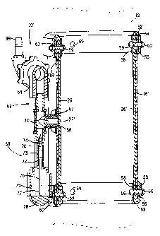
Figs. 5 and 6 show an alternative embodiment according to the
present invention which is similar to the principles and operations of the
valve 10
shown in Figs. 1 through 4 with the following exceptions and/or additions.
Like
numbers are used to denote like parts previously described.
In valve 10', the outer rigid casing 16' is provided by a single
cylindrical shell formed of a fiberglass reinforced composite. Flexible rubber
sleeve 26' is disposed radially inwardly of casing 16' and defines gas chamber
28'
between casings 16' and rubber sleeve 26'. As seen at the extreme ends of the
valve
10', the upper and lower ends 52, 53 of the rubber sleeve 26' are folded over
top and
bottom ends 54, 55 of the rigid casing 16'. An inner metal support ring 56 is
placed
to the inside of the sleeve 26', and an outer metal support ring 58 is
positioned to
the outside of the folded over portion of the sleeve 26'. A series of bolts 59
are
passed through the inner support rings 56, the folded over sleeve ends 52, 53,
the
casing 16' and the outer support rings 58, and nuts 60 are attached to the
shafts of
the bolts 59 so as to hold the assembly tightly together without any welding.
An air intake/exhaust system 62 is comprised of a gas port 30' in
communication with a relief valve 64 and a gas line 36'. Relief valve 64 is
equipped with a muffler 65 as seen in Fig. 5. Gas port 30' is attached, such
as by
drilling and tapping a hole in the shell 16, and screwing a bushing 66 with
threads
into the tapped hole until the brushing 66 is secure. Once this is completed,
a lock
nut 67 is tightened on the bushing 66 to prevent the gas port 30' from coming
loose.
Gas port 30' extends through the casing 16' so that it communicates with gas
-5-
CA 02424408 2003-04-02
chamber 28'. Gas line 36' channels a source of gas to gas chamber 28, the flow
of
gas being controlled manually or by remote control as previously described.
Attached to a lower portion of the gas port 30' is a pressure sensitive
off/on indicator 68 which is in communication with the gas being selectively
supplied to the gas port 30'. The off/on indicator 68 includes a moveable
valve
element 70 which is normally biased upwardly by a compression spring 72
disposed
in a cylinder 73 fixed in a passageway 74 to prevent gas from entering
passageway
74 in communication with a cup-like housing 75. The valve element 70 has a
depending elongated plunger 76 which passes through the compression spring 72,
the cylinder 73 and the housing 75, and has an opposite end 77 attached to a
dome-
like, preferably colored, indicating element 78 which extends and retracts
relative to
housing 75 depending on the pressure of gas delivered to the gas port 30'.
It should be understood that the off/on indicator 68 may take other
forms. For instance, one could employ a battery-operated light or sound device
which is activated by gas pressure to accomplish the same concept as described
above.
In operation, pressurized gas, such as air, is delivered through air
intake/exhaust system 62 into gas chamber 28' via gas port 30'. Rubber sleeve
26'
expands radially inwardly to constrict delivery hose 12 to the point where
flow of
concrete through hose 12 is interrupted. At the same time, gas pressure in the
passageway 74 will act to unseat valve element 70 against the bias of spring
72 and
move plunger 76 so that the indicating element 78 will extend away from the
housing 75 to give visual indication to the operator that the shut-off valve
10' is
closed upon the hose 12. When it is desired to open the shut-off valve 10',
delivery
of gas to gas line 36' is stopped and pressurized gas is exhausted quickly
through
the relief valve 64 and muffler 65. As this happens, the spring 72 will move
the
valve element 70 to block passageway 74 so that the plunger 76 and indicating
element 78 will retract inside housing 75 (as shown in phantom lines of Fig.
6) to
indicate to the operator that the valve 10' is open whereupon concrete may
again
flow freely through hose 12.
-6-
CA 02424408 2003-04-02 It should be understood that the shut-off valve 10'
operates in a more
efficient manner to more quickly exhaust gas due to the inclusion of the
relief valve
64 which enables a reduction of about 50 percent (from eight seconds to four
seconds) in the opening/closing time of the valve 10'. This improvement in
reaction
time is conveniently transmitted visually to the operator via the pressure
responsive
off/on indicator 68. It should be further appreciated that the present
invention
involves a reduction in the machining and number of components, a reduction in
assembly time and the elimination of welding, all of which contribute to lower
cost
with an improved response.
It is recognized that other equivalents, alternatives, and modifications
aside from those expressly stated, are possible and within the scope of the
appended
claims.
-7-