Note: Descriptions are shown in the official language in which they were submitted.
CA 02424865 2003-03-13
Description
Hydrogen absorption and desorption method
for hydrogen storage alloy and a fuel cell using the method
Technical Field
The present invention concerns a hydrogen absorption and desorption
method of repeating pressurization and depressurization of hydrogen for a
hydrogen storage alloy and, more in particular, it relates to a hydrogen
absorption and desorption method of increasing the amount of hydrogen desorbed
in a practical pressure range and a temperature range, as well as a fuel cell
using
the absorption and desorption method.
Background Art
At present, along with increase in the amount of use of fossil fuels such as
petroleum, there are fears of acid rains caused by NOx (nitrogen oxides) and
also
global warming due to increasing COa: Since such environmental disruption
gives severe problems, intense attention has been attracted to the development
and practical use of various clean energies gentle to the earth. One of new
energy development is a practical use of hydrogen energy. Hydrogen is a
constituent element of water present infinitely on tl~~,?earth which can be
formed
by using various primary energies, as well as it can be used as a fluid energy
instead of existent petroleum with no worry of environmental disruption since
combustion products of hydrogen consists only of water. Further, different
from
electric power, it has excellent characteristics such as relatively easy
storage
thereof.
Accordingly, studies on hydrogen storage alloys as storage and
CA 02424865 2003-03-13
transportation media of hydrogen have been made vigorously in recent years,
and
practical use therefor has been expected. The hydrogen storage alloys are
metals
and alloys capable of absorbing and desorbing hydrogen under appropriate
conditions. By the use of the alloys, hydrogen can be stored at a lower
pressure
and at a higher density compared with existent hydrogen reservoirs and the
volumic density thereof is substantially equal with or higher than liquid
hydrogen or solid hydrogen.
As the hydrogen storage alloys, in addition to AB5 type alloys such as
LaNis or AB2 type alloys such as TiMnz already put to practical use at
present,
hydrogen storage alloys having body-centered cubic structures such as V, Nb,
Ta
or CrTiMn system and CrTiV system have also been studied as proposed, for
example, in JP-A No. 10-10225.
For the hydrogen absorption and desorption method, methods of
absorbing and desorbing hydrogen at a constant temperature have been
described in JP-A No. 10-110225 and No. 7-252560. In the latter JP-A No. 7-
252560, while the activating pre-treatment is conducted by a two-stage
treatment
of a low temperature pre-stage and a post-stage, the absorption/desorption
temperature is constant (20qC). Further, while JP-B No. 59-38293 describes a
method of heating to 100qC (column 4, lines 32 - 39), this is also an
absorption
and desorption method at a constant temperature.
On the other hand, application use utilizing hydrogen described above
includes fuel cells. Since the fuel cells have higher power generation
efficiency
compared with thermal power generation, they have been studied vigorously and
remarkable improvement for the power generation efficiency in the feature has
been expected. As the fuel for the fuel cell, hydrogen in natural gas or
methanol,
etc. is utilized. Since the fuel cells using hydrogen as the fuel are simple
in the
structure and exhibit excellent performance, alkali electrolyte type and solid
2
CA 02424865 2003-03-13
polymeric film type fuel cells with a power of about 10 kW have been used as
an
energy source for mobile engines such as satellites, deep-sea vessels, and
electric
automobiles.
[Subject to be Solved by the Invention
In AB5 type alloys such as LaNis or BCC type alloys put to practical use
at present, the equilibrium pressure with hydrogen can be controlled by
controlling the alloy ingredients. Further, while the equilibrium pressure
between the hydrogen storage alloy and hydrogen can be controlled by the
operation temperature, such existent methods lack in the technical idea of
elevating the temperature in the final stage of hydrogen desorption thereby
increasing the amount of hydrogen that can be utilized effectively.
Accordingly, an object of the present invention is to provide a hydrogen
absorption and desorption method capable of absorbing and desorbing hydrogen
in more amount by effectively utilizing hydrogen, as well as a fuel cell using
the
method.
Disclosure of the Invention
For solving the foregoing subject, a hydrogen absorption and desorption
method for a hydrogen storage alloy according to the present invention has a
feature in that an alloy temperature of said hydrogen storage alloy in the
final
stage of a hydrogen desorption process (T2) is made higher than an alloy
temperature of the hydrogen storage alloy in the initial stage of the hydrogen
desorption process (T1) (T2 > T1), and the alloy temperature in the final
stage
(T2) is controlled to a temperature where a hydrogen pressure at a boundary
point between a plateau region of a PCT curve and an inclined region adjacent
thereto is a normal pressure or higher.
According to the feature described above, since the alloy temperature of
3
CA 02424865 2003-03-13
the hydrogen storage alloy in the final stage of the hydrogen desorbing
process
(T2) is made higher than the alloy temperature in the initial stage of the
hydrogen desorption process (T1), the occluded hydrogen which was neither
desorbed nor utilized in the prior art can be desorbed and utilized, as well
as
since the alloy temperature in the final stage (T2) is controlled to such a
temperature that a hydrogen pressure at the boundary point between a plateau
region of a PCT curve and an inclined region adjacent thereto is at a normal
pressure or higher, requirement of a negative pressure pump can be avoided in
the handling of desorbed hydrogen, and desorbed hydrogen can be obtained at a
pressure easy to practical use.
In the present invention, the time point for elevating the alloy
temperature by heating is defined as at the final stage of the hydrogen
desorption
process. This is because temporal elevation of temperature for the alloy only
during the initial stage of the hydrogen desorption process or in a certain
period
during the hydrogen desorption process has an effect of increasing the
hydrogen
desorption speed but it does not increase the amount of hydrogen that can be
utilized effectively. Further, in order to increase the amount of hydrogen
that
can be utilized effectively, it is effective to elevate the temperature at the
final
stage of the hydrogen desorption process.
Further, the boundary point between the plateau region and the inclined
region adjacent thereto of the PCT curve defined in the present invention is
an
intersection between a tangential line of an inclined region and a tangential
line
near the central portion of the plateau region in the PCT curve in accordance
with the Sievert's law and, in a case where the turning point can be defined,
it is
an intersection with a tangential line passing through the turning point.
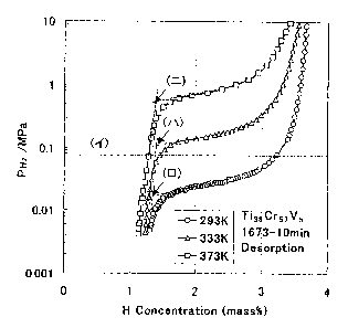
Fig. 1 shows high pressure PCT curves in the desorption process of a
T138Cr57V5. Symbols (~f ), ( a ) show the range for the boundary points. The
4
CA 02424865 2003-03-13
amount of hydrogen utilizable in a range from a normal pressure to 30 atm is
0.3% at 20°~C, 1.8?% at 60°r0 and 1.84% at 10090 of the hydrogen
storage alloy
temperature in a case where the hydrogen is desorbed at a constant
temperature.
Further, in a hydrogen desorption specimen at 60°r0 according to the
invention,
the amount of hydrogen that can be utilized can be increased to 2.15°/
by
elevating the temperature to 100~C in the final stage of the hydrogen
desorption
process. In the drawing, arrow (») denotes a boundary point which is at 0.12
MPs. Further, in a hydrogen desorption specimen at 100°~C, the
hydrogen
amount was increased to 1.93°/ by elevating the temperature to
150°~C. As
described above, it can be seen that hydrogen of high practical utility that
can be
utilized effectively can be increased remarkably by elevating the temperature
to
a level where the boundary point is within a range from 0.08 MPs to 1 MPs.
In the hydrogen absorption and desorption method of the hydrogen
storage alloy according to the invention, it is preferred that the hydrogen
storage
alloy has a hydrogen pressure of from 0.08 MPs to 1 MPs at the boundary point
between the plateau region and the inclined region adjacent thereto of the PCT
curve of the alloy at the alloy temperature in the initial stage of the
hydrogen
desorption process (T1).
With such a constitution described above, the alloy having a hydrogen
pressure of 0.08 MPs to 1 MPs at the boundary point between the plateau region
and the inclined region adjacent thereto of the PCT curve of the alloy at the
alloy
temperature in the initial stage of the hydrogen desorption process (T1) can
increase the effective hydrogen effectively by making the temperature of the
alloy
to the high temperature (T2) in the final stage.
In the hydrogen absorption and desorption method for the hydrogen
storage alloy according to the invention, the alloy temperature in the final
stage
(T2) is preferably 150~C or lower.
CA 02424865 2003-03-13
With such a constitution described above, the alloy temperature in the
hydrogen desorption process (T1) and the alloy temperature in the final stage
of
the hydrogen desorption process (T2) can be made near the normal temperature
region, which can save the heat energy required for temperature elevation
(heating), as well as reduce the cost of the temperature elevation device and
improve the practicality.
In the hydrogen absorption and desorption method for the hydrogen
storage alloy according to the invention, it is preferred to define the
process at or
after the instance where hydrogen contained in the hydrogen storage alloy is
decreased to any residual amount of 50% or less in the hydrogen desorption
process as the final stage of the hydrogen desorption process.
Elevation of the alloy temperature by conducting heating in the initial
stage of the hydrogen desorption process where hydrogen contained in the
hydrogen storage alloy is 50% or more can increase the hydrogen desorption
rate
but the amount of effectively utilizable hydrogen is not increased, whereas
heating necessary for increasing the amount of effectively utilizable hydrogen
can
be conducted efficiently with the constitution described above.
In the hydrogen absorption and desorption method for the hydrogen
storage alloy according to the invention, it is preferred to define, as the
final
stage of hydrogen desorption, the process at or after the instance where
hydrogen
contained in the hydrogen storage alloy is decreased to any residual amount of
25% or less during the hydrogen desorption process.
Elevation of the alloy temperature by conducting heating in the initial
stage of the hydrogen desorption process where hydrogen contained in the
hydrogen storage alloy is 25°/ or more has an effect of increasing the
hydrogen
desorption rate but the amount of effectively utilizable hydrogen is small,
whereas heating necessary for increasing the amount of effectively utilizable
6
CA 02424865 2003-03-13
hydrogen can be conducted efficiently with the constitution described above.
That is, it is effective to elevate the temperature in the final stage of the
hydrogen desorption process at or after the instance where hydrogen in the
hydrogen storage alloy is decreased to any residual amount of 50% or less,
more
preferably, 25% or less, by which the amount of effectively utilizable
hydrogen
can be increased with less heat energy (amount of heating).
A fuel cell according to the present invention comprises a hydrogen
storage tank for incorporating a hydrogen storage alloy, a temperature control
device for elevating or lowering directly the temperature of the hydrogen
storage
alloy or an atmospheric temperature of the storage alloy, a fuel cell of
outputting
electric power via chemical change of hydrogen supplied from the hydrogen
storage tank and a control section for conducting control such that the alloy
temperature of the hydrogen storage alloy in the final stage of a hydrogen
desorption process (T2) is made higher than the alloy temperature of the
hydrogen storage alloy in the initial stage of the hydrogen desorption process
(T1)
(T2 > T1) and that the alloy temperature in the final stage (T2) is at a
temperature where the hydrogen pressure at the boundary point between a
plateau region and an inclined region adjacent thereto of a PCT curve is a
normal
pressure or higher.
According to the feature, since the alloy temperature of the hydrogen
storage alloy in the final stage of the hydrogen desorption process (T2) is
made
higher than the alloy temperature in the initial stage of the hydrogen
desorption
process (T1), occluded hydrogen which was never desorbed and utilized in the
prior art can be desorbed and utilized, as well as since the alloy temperature
in
the final stage (T2) is controlled to a temperature where the hydrogen
pressure at
the boundary point between the plateau region and the inclined region adjacent
thereto of the PCT curve is the normal pressure or higher, desorbed hydrogen
can
7
CA 02424865 2003-03-13
be obtained at a pressure higher than the normal pressure easy to be served
for
practical use and requirement of a negative pressure pump for handling the
desorbed hydrogen can be avoided.
In the fuel cell according to the invention, it is preferred that the control
section can properly control the pressure, temperature and flow rate of the
hydrogen gas supplied to the hydrogen storage tank and the fuel cell.
With the constitution described above, by controlling the pressure,
temperature and the flow rate of the hydrogen gas, the amount of electric
power
generation in the fuel cell can be properly controlled depending on the load
and
the utilization efficiency of hydrogen used in the fuel cell can be improved.
In the fuel cell according to the invention, it is preferred that the
temperature control device described above can utilize the heat dissipated
from
the fuel cell or the heat of exhaust gases exhausted from the fuel cell for
the
temperature elevation.
With the constitution described above, since the dissipated heat or
discharged heat from the fuel cell can be utilized for the temperature
elevation of
the hydrogen storage alloy, electric Bower, etc. are no more required for the
temperature elevation of the hydrogen storage alloy, which can improve the
efficiency in the overall hydrogen fuel cell.
Brief Description of the Drawings
Fig. 1 is a graph showing high pressure PCT curves (method determined
original point before activation) in the desorption process of a TissCrs~Vs
alloy
used in Example 2 of the invention.
Fig. 2 is a graph showing high pressure PCT curves in the desorption
process of an MmNi~.sAlo.s alloy used in Example 1 of the invention.
Fig. 3 is a graph showing high pressure PCT curves (method determined
8
CA 02424865 2003-03-13
original point on evaccuatio~ of a Tis8Cra7Vs alloy used in Example 2 of the
invention.
Fig: 4 is a system flow showing an embodiment of a fuel cell in Example 1
according to the invention.
Best Mode for Practicing the Invention
An embodiment of the present invention is to be described with reference
to the drawings.
(Example 1)
After weighing commercially available starting materials, the mixture
was subjected to arc melting in argon with a water cooled copper hearth to
prepare 20 g of an MmNi4.sAlo.s alloy, which was successively kept at
1100°~C for 8
hours and then quenched. The quenched alloy specimens were measured for
their high pressure PCT characteristics with a PCT characteristic measuring
apparatus manufactured by Suzuki Shokan, Japn.
Fig. 2 shows high pressure PCT curves in the hydrogen desorption
process of the MmNi~.sAlo.s alloy. A hydrogen pressure at a boundary point
between a plateau region and an inclined region of a PCT curve at 20°0
is 0.11
MPa. Measured data indicated by squares (D) show a PCT curve where
hydrogen was desorbed at a constant temperature of 2090, whereas measured
data indicated by circles (0) show a PCT curve in a case of elevating the
temperature of the hydrogen storage alloy from 20°r0 to 10090 at an
instance
where the residual amount of hydrogen was 21%. It could be verified from the
data that the effective hydrogen occlusion amount could be increased by
12°/ by
heating the hydrogen storage alloy to 100q0 from the instance where the amount
of residual hydrogen was 21% in a case of utilizing the hydrogen storage alloy
9
CA 02424865 2003-03-13
within a range from 0.1 MPa to 1 MPa.
Then, a hydrogen fuel tank was manufactured by wing the MmNi4.sAlo.s
alloy and a fuel cell was constructed. Fig. 4 is a system flow chart showing
an
embodiment of a fuel cell. The hydrogen fuel tank is provided with a solenoid
valve Vl l for introducing starting hydrogen, as well as a solenoid valve V1
for
supplying hydrogen to the fuel cell and a solenoid valve V2 for recovering the
hydrogen returned from the fuel cell to the tank disposed between the tank and
the fuel cell 1, and they are adapted to supply hydrogen by a pump P2.
Further,
pressure valves B1 and B2 and flow meters FM are provided in the course of the
pipeline for controlling the pressure and the flow rate of hydrogen, and the
entire
system including a heat exchanger 5 utilized for temperature elevation and
temperature lowering is controlled by the control device 3. In the heat
exchanger
5, heat exchange is conducted between exhausted heat possessed in steams at a
relatively high temperature exhausted from the fuel cell 1 and cold water as a
cold temperature medium and temperature sensors TS1 - TS3 or the flow meters
FM and the pumps are controlled to control the temperature to an aimed level.
In the fuel cell 1, a DC power can be obtained by reaction between oxygen and
hydrogen and an inverter 2 for converting the DC power into a predetermined AC
power is connected with the fuel cell.
At first, a hydrogen reservoir at a high pressure was connected with a
hydrogen supply port of the tank 4 and the solenoid valve Vll was opened to
supply hydrogen into the tank up to a hydrogen pressure of 1 MPa. In this
case,
the pump 5 was operated to send external air to the heat exchanger and the
circulation pump 3 was controlled properly such that the temperature of the
tank
(TO) was at 20°C. After the completion of occlusion, the solenoid valve
Vll was
closed and, successively, opening/closure of the solenoid valves Vl and V2 and
the
pressure valves Bl and B2 were controlled to supply hydrogen to the fuel cell
1.
CA 02424865 2003-03-13
In this step, the temperature of the hydrogen fuel tank was kept at 20~ in the
initial stage of hydrogen supply and it was elevated to 8590 in the final
stage
where the amount of residual hydrogen was decreased to 30°/.
At the same time with the supply of hydrogen, oxygen was supplied from
an oxygen electrode, and oxygen and hydrogen were reacted in the fuel cell to
give electric power. As a result of examining the electric power, increase of
the
electric power by about 10% was confirmed by the temperature elevation for the
hydrogen fuel tank from 20~C to 85~C in the final stage of the hydrogen
desorption process.
(Example 2)
After weighing commercially available starting materials, the mixture
was subjected to arc melting in argon with a water cooled copper hearth to
prepare 30 g of a TissCrs~Vs alloy, which was successively kept at 1400~C for
10
min and then quenched in iced water.
Fig. 3 shows high pressure PCT curves for the TissCrs~Vs alloy. The
boundary point is at 0.1 MPa. Triangles (D) show a PCT curve in the hydrogen
desorption process in a case of absorbing and desorbing the alloy at 100~C.
Squares (D) show a PCT curve for hydrogen desorption process in a case of
conducting dehydrogenation at 10090 and then absorption at 6090 and desorption
at 6090. Circles (~) show a PCT curve in the hydrogen desorption process in a
case of conducting absorption in the same manner as in "D" and temperature
elevation from 60q0 to 100~C in the final stage of the desorption process.
When
temperature elevation was conducted in the hydrogen desorption process (~),
the
amount of residual hydrogen was about 43°/. It was verified from the
data that
the effective hydrogen occlusion amount could be increased by 19% in a case of
using the hydrogen fuel tank in a range from 0.1 MPa to 1 MPa by heating the
11
CA 02424865 2003-03-13
hydrogen storage alloy to 10090 from the instance where the amount of residual
hydrogen was 43°~.
While the embodiments of the present invention have been described
with reference to the drawings, the invention is not limited to each of the
examples but it will be apparent any variations or modifications within a
range
not departing the gist of the invention is also included in the scope of the
invention.
For example, in Example 1, T2 was controlled at 85~C since water was
used for cold temperature medium. However, the invention is not restricted to
this same but heating by a heater or the like can also be utilized. In the
same
manner, a method of utilizing coolant other than water for cooling and a
method
of enabling both cooling and heating by a Peltier device or the like can also
be
utilized. Further, in the application use of supplying electric power to
electronic
equipments, a DC/DC converter may be connected instead of the inverter.
Further, in each of the examples described above, while the MmNi4.sAlo.s
alloy or the TissCrs7Vs alloy was used as the hydrogen storage alloy, the
invention
is not restricted to them. As the alloy, any hydrogen storage alloy capable of
occluding and releasing hydrogen of a practical capacity under a practical
pressure can be used.
Description for References
1 fuel cell
2 inverter
3 control device (control section)
4 hydrogen fuel tank (hydrogen storage tanl~
heat exchanger (temperature control device)
12