Note: Descriptions are shown in the official language in which they were submitted.
CA 02424889 2003-04-03
WO 02/31287 PCT/US01/30967
COMPOSITE BUILDING MATERIAL
Background of the Invention
Field of the Invention
This invention relates to a composite building material, and more particularly
to a
building material incorporating a lightweight core and one or more fiber
cement skins
formed on opposite sides of the core.
Description of the Related Art
Fiber-reinforced cement products such as water-resistant building sheets have
been
used for building since 1895. In recent history, reinforcing fibers used in
such products
have included not only asbestos fibers, but also cellulose (wood) fibers (see
Australian
Patent No. AU 515151), metal fibers, glass fibers and other natural fibers.
Typically the
density of such building sheets is from 1.2-1.7 g/cm3, the variation in
density typically
being achievable by compression and dewatering of the fiber cement slurries
used in
manufacture, and by varying the amount of fiber used.
The densities of fiber cement described above mean the products are heavier
than
timber-based products of equal dimension and are more difficult to cut,
machine and nail
than timber and timber-based products. The density of lumber typically ranges
from 0.7-
0.9 g/cm3 for dry hardwoods and from 0.38-0.6 g/cm3 for dry softwoods. Thus, a
fiber
cement material of density similar to lumber would enable products to be
manufactured that
were lighter, more nailable, easier to cut, and easier to machine, while
retaining the
durability, fire-resistant, rot-resistant, and water-resistant properties of
fiber cement.
Summary of the Invention
Fiber cement building materials are commonly installed to external surfaces of
building envelopes. The outside surface of the fiber cement product is exposed
to local
weather conditions and is subjected to stresses brought about by changes in
temperature
and humidity, UV exposure, and exposure to pollutants and carbon dioxide in
the
atmosphere. A building product that has the exterior durability, planar
strength, and the
resistance to moisture degradation of fiber cement on the outside surfaces,
along with a
modified core to provide one or more special properties to the composite, is
desired. The
special properties may include, but are not limited to:
CA 02424889 2003-04-03
WO 02/31287 PCT/US01/30967
= Lighter weight for ease of handling of full sheets and long lengths of
product,
= Ease of cutting similar to gypsum wallboard to ensure quick and easy
installation of the product by score-and-snap cutting with a utility knife,
= Low thermal conductivity for insulation of walls in building structures from
the outside environmental conditions,
= Thermal fire insulation and low thermal shrinkage to provide resistance to
the progression of heat and fire through building walls and ceilings,
= Low moisture transmission to control and direct moisture flow and
permeation of water and moisture into building walls, ceilings and roofs, and
= Low acoustic transmission and high acoustic absorption to reduce noise
transmission throughout rooms in a building.
The desired properties can be achieved with a sandwich composite design using
fiber cement facing on a core having a composition tailored for the specific
properties.
This invention in one embodiment generally pertains to a composite building
material comprising a lightweight core with a thin fiber cement facing
material or fiber
cement skin bonded to one side of the core and a second facing material bonded
to the other
side. The fiber cement facing that is used on at least one of the faces of the
building
material is preferably less than about 3/16" thick, more preferably less than
about 1/8"
thick. Thinner skins provide an overall light composite because the skin
material is of
higher density than the core material. The fiber-cement facing is preferably
in a preformed
green (uncured) state at the time of assembly of the skins and the core into
the sandwich
composite.
It is an object of this invention to produce composite building materials that
can be
designed specifically for applications such as but not limited to tile backer,
wallboard, wall
panel, siding, trim, sheathing, decking, flooring, structural members,
fencing, roofing, roof
decking, or substrates thereof. The bulk of the physical properties (strength,
durability,
etc.) can be tailored by varying the composition of the facing material and/or
the core. The
fabrication of composites with a particular set of mechanical properties can
be done with
the proper choice of facing material and thickness. The density of the
composite can be
reduced by foaming the core slurry and/or by adding low-density filler
materials. The
uncured fiber cement facings are preformed and preferably continuous in
length. The use
-2-
CA 02424889 2009-01-08
of continuous, preformed fiber cement facing sheets simplifies the manufacture
of the
composite since only the core composition is cast, instead of casting one each
for the core
and for the facing. Also, the use of continuous, preformed fiber cement facing
sheets
eliminates the need for separate carrier sheets.
It is a further object to produce composites with improved properties by co-
curing the
core and facings. Manufacturing with uncured fiber cement sheet offers greater
flexibility in
the surface texture, surface profile, corner profile, and composite
properties. Penetration of
the core slurry into the uncured. fiber cement facing and subsequent co-
curing of the core and
skins produces superior interlayer bonding, resulting from mutually
interpenetrating
mechanical and chemical bonding. The bonding can be further improved with a
cementitious
bonding layer applied to the core side of the facing. Controlling the water
content and/or
degree of precure of the green sheets to enable sufficient penetration of the
core slurry into
the void network of the sheet enhances interlayer bonding. This leads to
stronger mechanical
interlock and chemical bonding after curing. Also, antifoaming agents,
thickening agents, or
other additives in the uncured facing can be used to collapse the foam at the
facing-core
interface. This leads to the formation of a dense interlayer that enhances
bonding by
increasing the surface area of contact between the core and facing. This
prevents the
occurrence of delaminations that would greatly reduce the strength and
durability of the
composites.
In one aspect of the present invention, a building material is provided
comprising at
least a first component and a second component provided adjacent the first
component. The
first component is provided as pre-formed, uncured fiber cement, wherein the
fiber cement is
of a single pre-mixed formulation reinforced with individualized fibers,
wherein the fibers
extend. in a substantially planar orientation substantially parallel to a
surface of the first
component. The uncured fiber cement is cured after providing the first
component adjacent to
the second component.
In one preferred embodiment, the building material is provided comprising a
lightweight, cement-containing, low cost core having a first side and a second
side. A pre-
formed fiber cement facing is provided on at least the first side of the core.
The fiber cement
facing is reinforced with individualized fibers, the fibers having a
substantially planar
orientation. The core and the facing are simultaneously cured to form the
building material.
In another aspect of the present invention, a method of manufacturing a
building
material is provided. The method comprises providing a first component,
wherein the first
component is a pre-formed fiber cement component of predetermined size and
shape is pre-
-3-
CA 02424889 2010-06-03
formed such that the fiber cement component is in a plastic state and is
uncured. The first
component is of a single, pre-mixed formulation not in the form of a slurry
and incorporated
therein are fibers that extend in a substantially planar orientation
substantially parallel to a
surface of the first component. The method further comprises providing a pre-
formed second
component of predetermined size and shape, wherein the second component
retains its shape.
The method also comprises positioning the first component adjacent the second
component
and curing at least the first component while the first component is adjacent
to the second
component to form the building material.
In one preferred embodiment, the fiber cement component is a fiber cement
skin, and
the second component is a lightweight cementitious core having a first side
and a second side.
The fiber cement skin is positioned adjacent a first side of the cem.entitious
core. The fiber
cement skin and the lightweight cementitious core are simultaneously cured to
form the
building material.
In a further aspect of the present invention there is provided a method of
manufacturing a building material comprising a pre-formed green fiber cement
component
and a pre-formed second component. The method comprises assembling the
building
material in an uncured state, wherein the pre-formed green fiber cement
component is of a
single pre-mixed formulation not in the form of a slurry and has a
predetermined size and
shape, is in a plastic state, retains its shape and incorporated therein are
fibers that extend in a
substantially planar orientation substantially parallel to a surface of the
pre-formed green
fiber cement component. The pre-formed second component is of predetermined
size and
shape and retains its shape. The pre-formed green fiber cement component is
positioned at
one time adjacent the pre-formed second component. The method also comprises
curing the
building material.
In a further aspect of the present invention there is provided a method of
manufacturing a building material. The method comprises assembling the
building material
in an uncured state, wherein a pre-formed green fiber cement component is of a
single pre-
mixed formulation not in the form of a slurry and has a predetermined size and
shape. The
pre-formed fiber cement component is in a plastic state, retains its shape and
incorporated
therein are fibers that extend in a substantially planar orientation
substantially parallel to a
surface of the pre-formed green fiber cement component. A pre-formed second
component is
of predetermined size and shape and retains its shape. The pre-formed green
fiber component
at least partially surrounds the pre-formed second component. The method of
manufacturing
a building material also comprises curing the building material.
-4-
CA 02424889 2009-01-08
Brief Description of the Drawings
Fig. 1 shows a cross-section of a 3-layer sandwich composite, comprising 2
facing
layers or skins and a solid core.
Fig. 2 shows an exploded view of a 3-layer sandwich composite, comprising 2
facing
layers or skins and a solid core.
Figs. 3A to 3C show examples of three of the many structural configurations
that can
be used for open-core composites. A vertical (open void cells are
perpendicular to the skins)
honeycomb core configuration is shown in Fig. 3A. A vertical configuration
composed of
symmetrically opposed corrugated core layers is shown in Fig. 3B. Fig. 3C
shows a
horizontal (open void cells are parallel to the skins), single corrugated core
layer.
Fig. 4 shows a sandwich panel with a solid core. The first facing (10) covers
one face
and both sides and overlaps both side edges of the opposing face.
Fig. 5 shows a plank with a solid core and a first facing that envelops the
faces and
sides.
Fig. 6 shows a trim board with a solid core and a first facing that envelops
the faces
and sides.
Figs 7A-7G show cross-sectional views of additional composite products that
can be
made in accordance with preferred embodiments.
Detailed Description of the Preferred Embodiments
1. Composite Structure and Composition
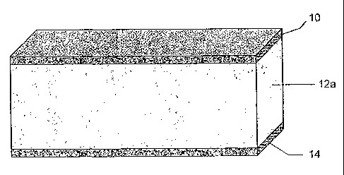
A preferred embodiment of the composite building material is shown in Fig. 1.
The
composite is preferably comprised of a lightweight core (12a), a fiber cement
outer layer,
skin or facing (10), and a second. outer layer, skin or facing material (14).
As used herein,
-4A-
CA 02424889 2003-04-03
WO 02/31287 PCT/US01/30967
the terms skin, facing, or outer layer are interchangeable. It will be
appreciated that the use
of facings and a core to form a composite is only one embodiment of the
present invention,
and thus, other building materials can be provided incorporating the concepts
described
herein without being limited to a core having a facing on one or both sides
thereof.
The lightweight core in one embodiment is comprised of a hydraulic
cementitious
binder, fillers, fiber, and foam and/or lightweight additives, as described
further below.
The fiber cement facing material (10) in one embodiment is comprised of
hydraulic
cementitious binder, filler, fiber, and additives. The second facing material
in one
embodiment is selected from a group that includes thin fiber cement, fibrous
mats, paper,
and polymeric coatings.
The embodiments of Figs. 1-3C consist of a composite building material
comprising
three primary layers through the cross section of the composite material
perpendicular with
the main planar axis of the composite:
= A first layer of fiber cement on at least one face of the building composite
(10),
= A middle layer of core material (12a to 12d),
= A second layer of either fiber cement or an alternate facing material on the
opposite face or any combination of the remaining faces of the composite
not faced by the first layer of fiber cement (14).
These embodiments may also have sub layers within or between the primary
layers to
provide improved interfacial bonding or provide other special functions to the
composite.
These sub layers or interlayers may also contain an embedded reinforcing
material
embedded in the layer, the reinforcing material being typical of materials
described herein
as the second outer layer.
It should be noted that the facings can be applied to any of the faces or
sides of the
core and are not restricted to the large primary faces of the composite. Figs.
5 and 6, for
example, show a plank and trim board, respectively, that have fiber cement
facings (10)
applied substantially entirely around a core as used in a plank and trim
board, respectively.
The surface of the fiber cement layer can be shaped, embossed or patterned if
needed for
aesthetics or functionality.
a. Materials for the Fiber Cement Outer Laver, Skin, or Facing
The fiber cement skin formulation in one embodiment preferably comprises:
-5-
CA 02424889 2003-04-03
WO 02/31287 PCT/US01/30967
= a hydraulic binder, preferably present in a concentration of about 10-80
wt%, more preferably about 20-50 wt%, and most preferably about 25-40
wt%;
= a filler material, preferably present in a concentration of about 0-80 wt%,
more preferably about 40-70 wt%, and most preferably about 45-65 wt%;
= fiber, preferably present in a concentration of about .1-25 wt%, more
preferably about 2-16 wt%, and most preferably about 5-12 wt%; and
= additives preferably present in a concentration of about 0-20 wt%, more
preferably about 0-10 wt%, and most preferably about 0-6 wt%.
The hydraulic binder used in the fiber cement is preferably Portland cement
but can
also be any hydraulic cementitious binder chosen from a group including, but
not limited
to: high alumina cement, ground granulated blast furnace slag cement, gypsum
heinihydrate, gypsum dihydrate, and gypsum anhydrite, or any mixtures thereof.
The filler, which can be reactive or inert material, is preferably ground
silica sand
but can also be any material chosen from the group including, but not limited
to:
amorphous silica, diatomaceous earth, rice hull ash, silica fume,
inicrosilica, hollow
ceramic spheres, geothermal silica, blast furnace slag, granulated slag, steel
slag, fly ash,
mineral oxides, mineral hydroxides, clays, magnesite or dolomite, metal oxides
and
hydroxides, polymeric beads, or any mixtures thereof.
The fiber cement additives can be chosen from a group including, but not
limited to:
silica fume, hollow ceramic spheres, cenospheres, geothermal silica, fire
retardants, set
accelerators, set retarders, thickeners, pigments, colorants, plasticizers,
dispersants, foaming
agents, flocculating agents, water-proofing agents, organic density modifiers,
aluminum
powder, kaolin, alumina trihydrate, mica, metakaolin, calcium carbonate,
wollastonite,
mineral oxides, mineral hydroxides, clays, magnesite or dolomite, metal oxides
and
hydroxides, pumice, scoria, tuff, shale, slate, perlite, vermiculite,
polymeric beads, calcium
silicate hydrate and polymeric resin emulsions, or any mixtures thereof.
Preferred
polymeric resins are products such as, but not limited to, acrylic latexes,
styrene-butadiene
latexes, or mixtures thereof. These latexes can be emulsions or be in a
redispersible powder
form. In portland cement-based materials, the latexes need to be stabilized to
withstand the
high-alkali environment.
-6-
CA 02424889 2003-04-03
WO 02/31287 PCT/US01/30967
The fibers used in the fiber cement are preferably cellulose wood pulp but can
also
be natural or synthetic organic or inorganic fibrous material chosen from the
group
including, but not limited to: ceramic fiber, glass fiber, glass ceramic
fiber, natural fibers
such as kenaf, hemp, flax and jute, carbon fiber, mineral wool, steel fiber,
synthetic
polymer fibers such as polyamides, polyesters, polypropylene,
polymethylpentene,
polyacrylonitrile, polyacrylamide, viscose, nylon, PVC, PVA, and rayon, or any
mixtures
thereof.
When cellulose fibers are used, they are preferably unrefined/unfibrillated or
refined/fibrillated cellulose pulps from sources, including but not limited to
bleached,
unbleached, semi-bleached cellulose pulp. The cellulose pulps can be made of
softwood,
hardwood, agricultural raw materials, recycled waste paper or any other forms
of
lignocellulosic materials. Cellulose fibers can be made by various pulping
methods. In the
pulping process wood or other lignocellulosic raw materials such as kenaf,
straw, and
bamboo, etc., are reduced to a fibrous mass by the means of rupturing the
bonds within the
structures of lignocellulosic materials. This task can be accomplished
chemically,
mechanically, thermally, biologically, or by combinations of these treatments.
The cellulose fibers used for reinforcing cement composite materials are
predominantly individualized fibers with partial or complete removals of
lignin
components from the fiber cell walls. In one embodiment, at least 90% of the
lignin
components are removed from the fiber cell walls. These fibers are preferably
prepared by
chemical pulping methods, which rely mainly on the effects of chemicals to
separate fibers.
Based on the chemicals utilized in the process, the chemical pulping methods
are classified
as Soda, Kraft, Kraft-AQ, Soda-AQ, Oxygen Delignification, Kraft-Oxygen,
Organic
Solvent methods, and Sulfite pumping, steam explosion pulping or any other
pulping
techniques. In the chemical pulping process, lignin, which acts as glue
holding cellulose
and hemicellulose together to provide mechanical strength in the wood, is
broken and
dissolved by chemical reactions.
These chemical reactions are usually carried out in a reactor, often called a
digester,
under a high temperature around 150 to 250 C for about 30 minutes to 2 hours.
The
cleavage of the bonds between lignin and cellulosic components results in
weakening of the
bonds among fibers. With aids of mild mechanical forces, cellulose fibers are
then
-7-
CA 02424889 2003-04-03
WO 02/31287 PCT/US01/30967
separated into individual fibers. By far the most common process for
individualized fiber
used in fiber cement composite materials is the Kraft process.
The fibers are more preferably fibrillated cellulose fibers, such as described
in
Australian Patent No. AU 515151. Fibrillation of the fibers involves first
dispersing the
fibers in water. This is preferably carried out in a hydrapulper of the kind
commonly used
in the paper making industry. A disc-type cellulose refiner is preferably used
to abrade,
shred, or fray the fibers to produce short, hair-like fibrils or tendrils
radiating from fine
fiber strands. This process significantly increases the exposed surface area
that is available
for bonding when incorporated into a cementitious matrix. This fiber
morphology enables
improved fiber-matrix bonding which results in improved strength and improved
impact
and abuse resistance. This improved, more efficient reinforcement per unit
volume of fiber
added reduces the volume addition of fiber needed to attain a given
performance level.
This reduction in needed fiber content can significantly reduce raw material
costs since
cellulose fibers cost substantially more than the other fiber cement
components.
In one embodiment, the fibers are dispersed at a consistency of about 1% to 6%
in a
hydrapulper, which also imparts some fibrillation. Further fibrillation can be
achieved
using a refiner or series of refiners. Once dispersed, the fibers are then
fibrillated to a range
of about 100 to 750 degrees of CSF (Canadian Standard Freeness), more
preferably
between about 100 to 650 degrees of CSF, more preferably between about 180 to
650
degrees of CSF. Dispersion and fibrillation can also be achieved by other
techniques such
as hammer-milling, deflaking, refining, shredding, and the like. Furthermore,
use of fibers
without fibrillation is also acceptable for some products and processes. In
another
embodiment, processing further comprises flash drying the fibers to a moisture
content of
about 5% to 50% using conventional flash drying systems.
The orientation of the fibers in the facing layers of fiber cement is
preferably
parallel to the planar layers of the material and this planar orientation
raises the tensile
strength of the skins 10 to 20% compared to random-oriented fiber in fiber-
reinforced
cement and concrete facings. More preferably, the fibers are substantially
oriented in the
direction of loading. It will be appreciated that the fibers can also be
aligned in different
planes to correspond to the desired direction of loading. The utilization of
planar-oriented
fibers is a more economical use of fiber. This is because fiber is more
expensive than the
inorganic matrix materials. Less fiber is needed to achieve the desired
strength and the
-8-
CA 02424889 2003-04-03
WO 02/31287 PCT/US01/30967
product is more durable because the more durable matrix component is less
diluted by
fiber. Again, as described above, preferred fibers for fiber cement facings
are cellulose
fibers that have been dispersed and fibrillated prior to manufacture of the
facings. These
discrete or individualized fibers have greater surface areas available for
bonding to
cementitious materials due to the fibrillation process. This higher degree of
bonding per
unit volume of the fiber cement leads to higher strengths and enhanced
durability.
The discrete or individualized fibers are proportionally mixed with the other
ingredients to form a mixture which can be a waterborne slurry, or a semi-dry
paste,
depending on the fabrication process to be used. In one embodiment, the
cellulose fibers
are mixed with cement, silica, a density modifier and other additives in a
well-known
mixing process to form a slurry or paste. In the mixer, regular cellulose
fibers and/or
natural inorganic fibers, and/or synthetic fibers can be blended with the
engineered fibers.
The fiber cement facing material may be formed into a shaped article from a
plastic
mixture or an aqueous slurry, with or without post pressing, by a number of
conventional
processes such as the:
= Hatschek sheet process;
= Mazza pipe process;
= Magnani process;
= Injection molding;
= Extrusion;
= Hand lay-up;
= Molding;
= Casting;
= Filter pressing;
= Fourdrinier forming;
= Multi-wire forming;
= Gap blade forming;
= Gap roll/blade forming;
= Bel-Roll forming;
= Wellcrete
= Others.
-9-
CA 02424889 2003-04-03
WO 02/31287 PCT/US01/30967
These processes may also include post-forming processes such as pressing,
embossing and others, after the article is formed but before the article is
cured. The
processing steps and parameters used to achieve the final product using a
Hatschek process
are similar to what is described in Australian Patent No. 515151. Thus, after
the processing
described above, the formed article is in a plastic state, enabling it to
retain its shape and be
capable of molding, but is not yet cured. Curing of the article, as described
below,
preferably occurs simultaneously with the core material.
b. Core Structure and Material
The core structure can be that of either a solid core (element 12a in Fig. 1
and Fig.
2) or an open core (elements 12b, 12c, and 12d in Figs. 3A, 3B, and 3C,
respectively).
Alternatively, the core can be considered to be homogeneous or non-homogeneous
(i.e., the
core is itself a composite). One or a combination of the following methods can
be used to
reduce the composite density:
= by assimilating large volumes of foam, with a bubble size preferably in the
range of about 0.02-1 mm, into the core slurry (solid core structure),
= by adding large volumes of low density materials to the core slurry (solid
core structure), or
= by forming the core with structural reinforcing material in such a way as to
form an open network having a large void volume (structural porosity, with
void dimensions typically ranging from about 10% to 90% or more of the
core thickness), but with a structural design that produces adequate core
strength (open core structure).
Large volumes of foam can be introduced to the core by adding foaming agents
directly to the slurry and foaming in situ, or preferably by adding foam from
a foam
generator. Voids can also be formed by adding a reactive gas-forming metal
powder to the
alkaline cementitious slurry, such as aluminum powder, to generate gas voids.
Low-density
additives are added directly to the slurry and require no additional
processing. Fabrication
of an open core structure involves construction of the core prior to assembly
of the
composite.
For the open core structural design, the core is preferably made from a strong
material in a shape and orientation that structurally reinforces and supports
the facing
materials. The objective is to create the strength and stability of a
monolithic sandwich
-10-
CA 02424889 2003-04-03
WO 02/31287 PCT/US01/30967
composite using an open structural design that incorporates large volumes of
void space to
reduce the composite weight. Such structural designs include open honeycombs
and
corrugations. The axis of the reinforcing core structure can be oriented
either parallel or
perpendicular to the planar axis of the composite. The structural reinforcing
material can
be made from fiber cement of a. composition and process described above, or
other cost-
effective, rigid materials such as plastic, fiber-reinforced plastic, metal,
or cardboard
material of a wall thickness preferably <_ 1/4 inch. A preferred method of
producing open
structural core designs such as honeycombs or other multi-celled structures is
by extrusion.
Another preferred embodiment is a co-extrusion of the core and facing
material.
The solid core formulation in one embodiment comprises:
= a binder, preferably present in a concentration of about 10-100 wt%, more
preferably about 20-50 wt%, and most preferably about 25-40 wt%;
= voids, formed by foaming the slurry, preferably in a size range of about
0.02-1.0 mm and present in a concentration of about 0-80 vol%, more
preferably about 20-70 vol%, and most preferably about 25-50 vol%;
= a filler material, preferably present in a concentration of about 0-80 wt%,
more preferably about 40-70 wt%, and most preferably about 45-65 wt%;
= fibers, preferably present in a concentration of about 0-5 wt%, more
preferably about 0.25-2.0 wt%, and most preferably about 0.5-1.0 wt%; and
= additives and admixtures preferably present in a concentration of about 0-20
wt%, more preferably about 0-10 wt%, and most preferably about 0-6 wt%.
The solid core composition preferably includes foam, fillers, additives, and
admixtures desired for core properties, and can be bound together by either
organic
(polymeric) or inorganic binders. The polymeric binders can be foamed or
unfoamed and
can contain fillers. The preferred binder to use in these materials is an
inorganic, hydraulic
binder chosen from the group including, but not limited to, Portland cement,
high-alumina
cement, ground granulated blast furnace slag cement, gypsum hemihydrate,
gypsum
dihydrate, gypsum anhydrite, or any mixtures thereof. More preferably the
binders are
Portland cement, gypsum hemihydrate, gypsum dihydrate, gypsum anhydrite, or
any
mixtures thereof.
Admixtures for the solid core slurries include viscosity modifiers,
accelerators,
retarders, foaming agents, and dispersing agents. Lightweight aggregates or
fillers are used
-11-
CA 02424889 2003-04-03
WO 02/31287 PCT/US01/30967
in addition to or in place of foaming agents to reduce core density.
Lightweight fillers
include expanded minerals such as perlite, vermiculite, shale, and clay,
expanded
polystyrene spheres, and fly ash. Moisture resistant additives used
individually or in
combination in these cores include emulsions of wax and/or asphalt, polyvinyl
alcohol,
siloxane emulsion, metallic soaps and stearates. Films or resinous coatings
formed by such
materials as styrene-acrylic latex can be used to further improve moisture
resistance and
surface quality. Additives used to improve fire resistance include gypsum,
mineral fibers
such as glass and wollastonite, mineral additives such as unexpanded
vermiculite, mica,
hydrated alumina, bauxite, clay, and any combinations thereof.
Other materials that can be used for the core include those described for the
facing
material above, those described in the section entitled "Overview of Other
Sandwich
Composite Embodiments."
c. Materials for the Second Outer Laver, Skin, or Facing
The second layer, or skin, if used, can be supplied in any generally planar
form,
such as a continuous fibrous or fiber-reinforced composite sheet, mat, plate,
film, or
coating, and can be made from substances such as metals, plastics, wood,
paper, organic or
inorganic fibers, cementitious or non-cementitious binders, fillers,
additives, or
combinations thereof. Preferred non-cementitious binders include but are not
limited to
polymers such as acrylic and styrene-butadiene latexes. In one embodiment, the
second
facing is fiber cement manufactured like the first facing described above. In
another
embodiment, the second facing is made of a different material from the first
facing. The
preferred materials to be used for the second skin include thin fiber cement,
fibrous mats,
paper, continuous strand two-dimensional mats, and polymeric coatings. The
preferred
fibrous mats are made from fiberglass, and can be either nonwoven (veils) or
woven
(scrims) using continuous or chopped fibers. The glass fibers are preferably
allcali resistant
or polymer coated. The surface of the second layer can be shaped, embossed, or
patterned
if needed for aesthetics or functionality. Other examples that can be used for
the second
facing are described in the section below entitled "Overview of Other Sandwich
Composite
Embodiments."
d. Composite Processing
It is preferred that after the manufacture of the components above, the
composite is
cured sufficiently to attain a minimum level of stiffness before subsequent
processing. If a
-12-
CA 02424889 2003-04-03
WO 02/31287 PCT/US01/30967
minimum level of strength is not attained, the physical manipulation required
for process
handling, cutting, and stacking can cause damage such as cracking within the
core or
delamination at the core-skin interface. Depending on the formulation, the
composite can
be air-cured, elevated-temperature cured, steam-cured, carbonated, or pre-
cured and then
autoclaved, or can be cured by combinations thereof. The length of time needed
for
composite stiffening and the temperature-time schedule needed for adequate
curing is
dependent on the formulation, the manufacturing process, and the size and
shape of the
composite. These factors can be adjusted with the use of set-controlling
admixtures and/or
adjusting processing parameters such as temperature. It will be appreciated
that curing as
described herein includes not only the curing of ceinentitious materials, but
also includes
non-cerentitious materials that set over time (e.g., polymers).
In one embodiment, an uncured fiber cement facing is preferably pre-formed by
a
slurry-dewatering process, such as the Hatschek process, to form a sheet that
is in a
moldable and uncured state prior to manufacture of the composite as described
above. The
composite building material is preferably assembled in an uncured state and
then cured.
The composite in one embodiment may preferably first be pre-cured in a pre-
cure chamber
at elevated temperature and relative humidity, or in a pre-cure chamber at
elevated
temperature and low humidity. Or preferably, the pre-curing is done for up to
80 hours at
ambient temperature, most preferably 24 hours or less. The article can then be
air-cured, in
one embodiment, for approximately 30 days. More preferably, the pre-cured
article is
autoclaved at an elevated temperature and pressure in a steam saturated
environment at
about 60 to 200 C for about 3 to 30 hours, more preferably about 24 hours or
less. The
time and temperature chosen for the pre-cure and cure processes are dependent
on the
formulation, the manufacturing process, the process parameters, and the final
form of the
product.
It will be appreciated that although the embodiments above describe
simultaneous
curing of the fiber cement facing and the core, the curing need not be done
simultaneously.
In other embodiments, curing can be performed consecutively or sequentially
when the core
and the fiber cement cure in different times. Moreover, the core can also be
made of a
material that does not require curing. In these embodiments, only the fiber
cement
component is cured. It will also be appreciated that the fiber cement can be
partially cured
or dried prior to forming the composite building material.
-13-
CA 02424889 2003-04-03
WO 02/31287 PCT/US01/30967
Manufacturing of the composite is done with an uncured fiber cement sheet to
produce stronger interfacial layer bonding to resist or essentially eliminate
core-skin
delaminations during handling, cutting, installation, and service. Co-curing
of the core and
skins produces a mutually interpenetrating mechanical and chemical bonding
between the
core and fiber cement skin. This type of bonding is stronger and more durable
compared to
forming the composite using cured fiber cement skins and does not require
adhesive to
bond the layers together. An accelerated hydraulic binder is preferably used
to speed up
continuous processing and enable higher throughput. The use of fiber cement
facings gives
the composite excellent moisture and abuse resistance. Good fire resistance
can be
obtained by the use of additives that effectively slow fire thermal conduction
and control
the permeability of the microstructure. The composites can also be designed to
have
interlayers, comprised of organic or inorganic materials or mixtures thereof,
that provide
special functionality such as by improving core-skin bonding, moisture
control, thermal
insulation, and fire protection.
The use of accelerating agents results in rapid stiffening desired for the
high speed,
continuous production of the composites. Penetration of the accelerants in the
core slurry
into the uncured facings during manufacture can accelerate the cure of the
fiber cement
facings. High production rates require the rapid stiffening of the composite
to enable
handling for cutting and stacking without collapse of the cores or damage to
the
composites.
The use of pre-formed, uncured fiber cement skins offers a number of
advantages as
outlined below: First, improved skin-core bonding resulting from mutually
interpenetrating
mechanical and chemical bonding. This improved bonding produces higher bending
strengths because this type of bonding is stronger and more durable than the
predominantly
mechanical bonding that occurs between cured fiber cement and the core found
in the prior
art. In addition, the improved bonding results in improved resistance to or
elimination of
core-skin delaminations that can occur during handling, cutting, installation,
and service.
The use of pre-formed, uncured fiber cement skin also results in reduced
manufacturing time. The uncured skins can be concurrently manufactured and
shaped,
imprinted, or embossed prior to assembly of the composite. An uncured bottom
skin can
also act as a carrier sheet and, by bending the flexible skin material upward
at the edges, it
can act as a mold for the core material, enabling continuous production of the
composite.
-14-
CA 02424889 2003-04-03
WO 02/31287 PCT/US01/30967
The methods and formulations described above also improve skin-core interlayer
formation. Admixtures such as anti-foaming agents in the uncured fiber cement
skin can
cause collapse of the foam structure at the skin-core interface to produce a
dense interlayer
that has a higher contacting surface area, resulting in a stronger bonding of
the core to the
skin. Also, careful control of the water content in the uncured skins can be
used to help
control the thickness of the dense interlayer that is formed. Drier skins wick
more water
from the core slurry and cause more collapse of the foam structure at the skin-
core
interface, resulting in a denser, thicker interlayer. A dense interlayer
material can be
applied to the core side of the fiber cement skin before assembly to further
improve core-
skin bonding.
Improved skin curing and skin properties also result from the embodiments
described above. Admixtures such as accelerating agents in the core slurry can
be wicked
into the fiber cement capillary network and accelerate the curing of the fiber
cement skins.
Cementitious material in the core slurry can be wicked into the fiber cement
skin capillary
network and substantially reduce the permeability of the fiber cement material
by filling the
capillaries with cementitious reaction products. This process has unexpectedly
resulted in
reductions of fiber cement permeability by as much as 95%.
e. Other Types of Composite Building Materials
It will be appreciated that the sandwich type composite materials described
herein
represent only one embodiment of the present invention, and thus, other types
of composite
building materials can also be made incorporating a pre-formed, uncured fiber
cement
component.
Fig. 7A illustrates one embodiment of a building material having a circular
cross-
section, wherein a lightweight material 16 such as described above surrounds a
fiber
cement component 18 such as described above. As shown in Fig. 7A, the fiber
cement
component 18 may be solid, or as shown in Figs. 7B and 7C, the fiber cement
component
18 can be annular. In Fig. 7B, a lightweight core 20, which may be the same
material or
different material from the outer component 16, is provided within the fiber
cement
component 18. In Figure 7C, this core 20 can also be annular to define a
hollow region of
the building material therewithin.
It will be appreciated that the components 16 and 18 in Figs. 7A-7C can be
switched, such that the fiber cement component surrounds a lightweight core.
Moreover, as
-15-
CA 02424889 2003-04-03
WO 02/31287 PCT/US01/30967
shown in Figs. 7D-7F, the building material need not be circular in shape, but
can assume
many other forms as well. Figs. 7D-7F illustrate one embodiment in which a
rectangular
core of lightweight material 24 is surrounded by a fiber cement facing 22 that
extends all
the way around the lightweight core 24. This facing 22 need not extend all the
way around
the core 24, but can also extend only partially around the core.
Further embodiments are illustrated in Figs. 7E and 7F, wherein a core 26 is
provided surrounded by two facing layers 24 and 26, one of which may be fiber
cement as
described above and the other of which can be the same or other material. In
Fig. 7F, it is
illustrated that the core 26 can be hollow.
Fig. 7G illustrates another embodiment wherein a lightweight core 30 is
sandwiched
between two facing layers 28 and 34, which may be fiber cement facings such as
described
above. The core 30 may be a composite material itself, reinforced with an
exemplary
reinforcement 32, which may be fibers or other materials.
2. Examples of Preferred Fiber Cement Skin Building Materials
One preferred embodiment of the invention comprises a building material made
from a lightweight, cement-containing, low-cost core which is at least
partially surrounded
by a fiber cement skin of thickness of less than about 3/16" thick, which when
cured, is of
high durability when exposed to sunlight, water, and atmospheric gases. The
bonding
between the fiber cement skin and the lightweight core is cementitious. The
thin, uncured
fiber cement skin is capable of being bent, folded, or profiled. Parts of the
core surface that
are not exposed to external weathering conditions may be left unfaced or faced
with another
sheet material herein described as the second outer layer, as desired.
The composite preferably has one or more of the following improved attributes,
including lower cost, durability and workability (including handling, cutting
to shape, and
fixing). Moreover, multifunctional perforinance is accomplished incorporating
any
combination of strength, abuse resistance, fire, acoustical transmission, and
aesthetics by
the use of sandwich composites as described above. In terms of
manufacturability, the use
of thin green sheet allows the skin to form a shapeable mold for the core.
Additives enable
the core and skin to be rapidly and controllably cured to form a
cementitiously bonded
monolith.
The use of pre-formed, uncured fiber cement skins in the production of
sandwich
composite boards is also far more efficient than using cured fiber cement
skins. The use of
-16-
CA 02424889 2003-04-03
WO 02/31287 PCT/US01/30967
cured fiber cement skins requires either the use of molds to contain a
flowable core slurry,
or the use of a non-flowable core mix which would have to be compacted to
attain a planar
profile. Either of these methods would considerably reduce production rates.
The plastic properties of the thin, preformed, green fiber cement skin of the
preferred embodiments also enable the skin to be wrapped around corners to
form
rectangular or profiled shapes not possible with cured fiber cement skins.
The multifunctional performance of these embodiments stems from the
combination
of the desired attributes of fiber cement, such as
= non-combustible,
= low flame spread,
= rot resistant,
= mold and fungus resistant,
= termite resistant,
= finished exterior surface for painting,
= exterior durability,
= resistance to degradation by moisture
= weather resistant,
= abuse resistant,
with additional functional attributes derived from a synergistic combination
of composite
design and materials, such as:
= shear strength of a framed wall similar to plywood and OSB sheathing,
= fire resistance of a framed wall similar to type X gypsum wallboard,
= thermal insulation similar to foamed plastic,
= structural adequacy for partition walls similar to engineered wood panels,
= acoustic absorption or low acoustic transmission,
= ability of the composite to be molded due to the plastic state of the fiber
cement skin to form folded corners, architectural profiles, or to make a full
wrap of fiber cement around the core material.
Examples of preferred multifunctional embodiments or products are described
below.
a. Fire + Cladding or Substrate
An example of a preferred product combines the desirable properties of fiber
cement with a fire resistive core material such that the composite attains a
fire rating
-17-
CA 02424889 2003-04-03
WO 02/31287 PCT/US01/30967
equivalent to type X gypsum wallboard when tested to ASTM E 119 for interior
and
exterior wall and ceiling assemblies. The advantage of this material is that
it provides both
fire resistance and a durable exterior surface in a single product.
Traditional systems
require multiple building products to attain equivalent functionality, such as
the
combination of a type X gypsum wallboard and an exterior cladding.
b. Thermal Insulation + Cladding or Substrate
Another example of a preferred product combines the desirable properties of
fiber
cement with a thermal insulating core material to achieve higher R-values when
tested in
accordance with ASTM C-177. The advantage of this material is that it provides
both
thermal insulation and a durable exterior surface to the structure.
Traditional systems
require a combination of building products to attain equivalent functionality,
such as the
combination of a foam plastic thermal insulation panel and an exterior
cladding.
c. Fire + Thermal Insulation + Cladding or Substrate
Another example of a preferred product combines the desirable properties of
fiber
cement with a thermal insulating core material to achieve higher R-values when
tested in
accordance with ASTM C-177, and also achieves a fire resistive rating
equivalent to 5/8"
thick type X gypsum wallboard. The advantage of this composite material is
that it provides
a fire resistive material, a thermal insulating material, and a durable
exterior surface to the
building assembly. Traditional systems require multiple building products to
attain
equivalent functionality, such as the combination of a type X gypsum
wallboard, a foamed
plastic thermal insulation panel, and an exterior cladding.
d. Shear + Cladding or Substrate
Another example of a preferred product combines the desirable properties of
fiber
cement with the racking shear strength, tested in accordance with ASTM E 72,
that is
provided by fixing the composite material in a framed assembly. The advantage
of this
material is that it provides the necessary shear strength in an assembly that
has a durable
exterior surface that is non-combustible and has low surface burning
characteristics (when
tested to ASTM E 84). Traditional systems such as APA Rated Sheathing and
Siding are
combustible and have higher surface burning characteristics.
e. Shear + Fire + Cladding or Substrate
Another example of a preferred product combines the desirable properties of
fiber
cement with a fire resistive core to achieve a fire rating equivalent to type
X gypsum
-18-
CA 02424889 2003-04-03
WO 02/31287 PCT/US01/30967
wallboard with adequate racking shear strength. The advantage of this material
is that it
provides shear strength, fire resistance, and a durable exterior surface in a
single building
product. Traditional systems require multiple building products to attain
equivalent
functionality, such as the combination of a type X gypsum wallboard and an APA
Rated
Sheathing or Siding.
f. Ability to Mold Shapes for Cladding or Trim or Decorative Substrates
Another example of a preferred product combines the desirable properties of
fiber
cement with the moldability of the thin, preformed, fiber cement green sheet
to form
architecturally desirable shapes. The advantage of this material is that it
provides a profiled
or shaped building product without the need for post-curing machining.
Traditional
profiled fiber cement is costly due to machining and tooling costs and the
costs associated
with the control and disposal of the dust generated from machining. Thicker,
lightweight,
and more complex shapes can be made with these composites compared to
traditional fiber
cement.
3. Overview of Other Sandwich Composite Embodiments
Having described preferred embodiments above, this section provides further
description of sandwich composites, including those encompassed by the
preferred
embodiments, as compared to other traditionally known types of sandwich
composites.
Generally, high strength-to-weight ratios can be attained using a sandwich
composite design combining high tensile strength skins with a lightweight,
rigid core.
Products using this type of design include aircraft wings, surfboards, boat
hulls, cool-room
panelized walls, and hollow-core doors. Sandwich composite building panels
include
paper-faced and fiberglass-mat-faced gypsum wallboards, fiberglass-scrim-
reinforced
cementitious tile backing boards and sheathing, and fiberglass-mat-faced
gypsum backing
boards.
a. Common building materials
Some common building materials have multi-layer construction, such as plywood
and fiber cement sheets. The composition and structure of each layer in these
particular
multi-layer materials is predominantly the same. Most fibrous reinforcement is
directional
or oriented within each layer, causing the physical properties of the
composite to be
directional. For example, the tensile strength of the composite is greater in
the planar
(layer) direction of the material than in the direction perpendicular to the
layers. The layers
-19-
CA 02424889 2003-04-03
WO 02/31287 PCT/US01/30967
can be positioned so that the composite has all its layers aligned in the
oriented direction,
such as with fiber cement, or with alternating layers aligned at right angles,
such as with
plywood. Aligning of adjacent, oriented layers at right angles greatly reduces
the
directionality in the composite properties.
Sandwich composites normally contain at least three primary layers and are
typically constructed of outer skins or facings covering relatively
lightweight cores. The
facing material of sandwich composites is usually chosen to impart strength to
the
composite. Exterior durability and moisture resistance frequently are not
inherent
properties of the high-strength skins. Fiber cement skins provide moisture
resistance and
durability that are desired for exterior building products such as siding,
wall panels, trim,
soffit, shingles and roofing tiles. High strength and low weight composites
are desired for
ease of installation of building products. This enables large sheets to be
handled without
excessive physical exertion and without the sheet breaking in bending.
Additions of foam
and/or lightweight fillers to the core mix of the sandwich composite reduce
the overall
weight of the composite.
b. Sandwich Composite Design Considerations
A sandwich composite structure, employing a lightweight core and relatively
high
tensile strength skins or facings, allows composite materials to be made thick
enough to
impart structural rigidity without rendering the product too heavy for ease of
handling. The
flexural strength of the composite is determined mainly by the tensile
strength of the skins
as long as the strength of the bonded interface between the skins and core is
adequate.
Failure due to bending of a sandwich composite can occur in three distinct
ways. The face
in tension may fracture, the face in compression may buckle and/or delaminate
from the
core, or the core may fail under shear load. Failure under shear load can
occur either close
to the interface of the core and skin, or within the core itself. Good
interfacial bonding
between the core and skins is needed when using lightweight core materials
that commonly
have high pore volumes.
c. Facing Materials of Building Material Sandwich Composites
Facing materials, or skins, are generally in the form of planar materials,
comprised
of sheets, mats, plates, films, and coatings. These facings can be made from
substances
such as metals, plastics, wood, paper, organic or inorganic fibers, and
cementitious
materials. Facing materials used for sandwich composite building materials as
described
-20-
CA 02424889 2003-04-03
WO 02/31287 PCT/US01/30967
herein include paper sheets, fibrous mats, fiber-reinforced cement (FC), and
fiber-mat
reinforced cement (FMC).
(1) Performance of Facing Materials in Moist Environments
The wet and dry strengths of a typical gypsum paper are compared to cellulose
fiber
cement made by the Hatschek process in Table 1 below. When dry, the gypsum
paper has
almost seven times the strength of the fiber cement. However, when the facings
were
saturated with water, the gypsum paper had less than 3% of its original
strength, whereas
the fiber cement retained about two-thirds of its dry strength.
Table 1
Tensile Strength
Facing Material Dry, MPa Wet, MPa
Gypsum Paper 40 1
(0.014" thick)
Fiber cement 6 4
(0.068" thick)
The papers used as facing materials are quite strong when dry, but lose almost
all of
their strength when exposed to wet environments. Water repellant additions to
the paper
improve the water resistance, but prolonged exposure to moisture can still
result in
degradation of the core-paper bond strength and the paper tensile strength.
This can
eventually lead to delamination of the paper from the core, and/or failure of
the core
material under minimal bending, shear or tensile loads.
(2) Surface Abuse Resistance of Facing Materials
Building materials such as wallboards are often subject to human traffic and
it is
desirable for the surface of building materials to have abuse resistance.
Fiber cement has
surface abuse resistance that is far superior to that of common paper-faced
building
materials such as gypsum wallboard. One measure of abuse resistance is the
resistance of
the surface to wear or loss of material from abrasion caused by people or
equipment
colliding with the surface of the wall. The surface abrasion resistance of
fiber cement and
gypsum wallboard was measured using the ASTM D4977 test method, modified using
a
25-1b. load on a steel brush. The abrasion depth was measured after 50 cycles
and found to
-21-
CA 02424889 2003-04-03
WO 02/31287 PCT/US01/30967
be 1.75 mm for the gypsum wallboard, compared to < 0.01 mm for the fiber
cement
wallboard.
(3) Flame and Fire Spread of Facing Materials
Another concern when designing and selecting building materials is the
resistance
of the surface of the material to promoting the spread of a fire and to supply
fuel to a fire in
a building. The surface fire resistance of paper-faced building products is
poor compared to
cement-based or inorganic-based materials due to the combustibility of the
wood fiber in
the paper facing.
(4) Fibrous-Mat Facings
When fibrous mats are used on wallboards, sheathing, and backing boards, they
are
usually made from uncoated or coated fiberglass. Fibrous mats can be either
nonwoven
(veils) or woven (scrims), and are composed of either chopped or continuous
fibers. Scrims
are generally more expensive than veils, but typically are stronger and more
durable.
Fibrous mats are more durable than paper facings. Although paper facings are
generally
stronger when dry, fibrous mats have much higher wet strengths. ASTM C 1154-99
defines
fiber-mat reinforced products (FMC) as "manufactured thin section composites
of hydraulic
cementitious matrices and non-asbestos fibers in two-dimensional scrims".
(a) Non-Woven Fiberglass-Mat Facings
Fiberglass mats have been used to improve the moisture and fire resistance of
gypsum board products. However, the composites are still susceptible to
deterioration after
prolonged exposure to moisture due to the solubility of gypsum in water. This
can
gradually reduce the strength of the core and of the mat-core interface.
Another concern
with fiberglass mat facings is skin irritation from handling the composites.
The glass fibers
contained in the mats are typically less than 0.001 inch in diameter and can
fracture and
become embedded in skin that comes into contact with the mats during handling.
These
embedded pieces of fiberglass cause irritation of the skin. Polymeric coatings
have been
claimed to further improve the water resistance of both paper and fiberglass
facings. Such
coatings generally slow the rate of water permeation into the core material.
(b) Fiberglass Scrims
Fiberglass scrims are used to reinforce board products such as Portland cement-
based ceramic tile backing boards. However, the durability of fiberglass
scrims made from
A-glass (soda-lime-silica) or E-glass (borosilicate) is greatly reduced when
they are used in
-22-
CA 02424889 2003-04-03
WO 02/31287 PCT/US01/30967
materials and building systems containing portland cement. The fiberglass is
attacked in
the highly alkaline environment of the portland cement and loses strength. The
actual
mechanisms are not well understood, but the attack commences with the
formation of an
alkali silicate gel. The glass fibers are relatively reactive due to a high
specific surface
(small diameter and high aspect ratio), and loss of structural mass to gel
formation can
quickly reduce the strength. To overcome this, the fiberglass must be coated
with a
polymeric material such as polyvinyl chloride to resist composite degradation
in a wet
environment. Another solution is to use fiberglass scrims made from alkali-
resistant (AR)
fibers. These fibers are composed of a soda-lime-silica glass containing a
minimum of 16
wt% zirconia. The addition of the zirconia significantly increases the cost of
the fiberglass.
Thus using coated fiberglass scrims is considerably less expensive than using
alkali-
resistant fiberglass scrims. Another concern with the use of fiberglass scrims
is that the
surface of the board will not be smooth unless the scrim is completely
embedded into the
core, or a suitable surface coating is applied.
(5) Fiber Cement Facings
ASTM C 1154-99 defines fiber cement (FC) products as "manufactured thin
section
composites of hydraulic cementitious matrices and discrete non-asbestos
fibers". Fiber-mat
reinforced cement products (FMC) are defined in ASTM C1154-99 as "manufactured
thin
section composites of hydraulic cementitious matrices and non-asbestos fibers
in two-
dimensional scrims".
Portland cement-based, fiber cement (FC) and fiber-mat reinforced cement (FMC)
facings are used in composite materials that have been developed for
applications such as
wall panels (King, U.S. Patent No. 5,002,620 and Cottier et al., Australian
Patent No.
661,704), trim boards (Gnatowski et al., U.S. Patent No. 5,693,409), and
various structural
materials. Two general types of these facings are used: 1) those manufactured
(prefabricated and cured) prior to assembly of the composite and 2) those
formed from
uncured material, in situ, as part of a sequentially layered composite. No
prior art has been
found in which continuous, preformed, uncured fiber cement facings have been
used to
manufacture sandwich composites as described above in the preferred
embodiments.
(a) Prefabricated and Cured Fiber Cement Facings
Prefabricated and cured fiber cement facings are used to form both cast-in-
place and
molded composites greater than 1-%2" thick. The cast-in-place composites, such
as
-23-
CA 02424889 2003-04-03
WO 02/31287 PCT/US01/30967
structural walls, panels, beams, girders, and joists, use prefabricated, cured
sheets as rigid
frameworks into which the cores are cast (Jones, Jr., U.S. Patent No.
5,473,849). The
composites are not designed to be installed onto a supporting wall framing
like most
wallboards or wall sheathings, but instead span from floor to ceiling, like
partition
composite wall panels. The method of forming this composite is similar to
pouring
concrete between formwork sheets, except the fiber cement facings (analogous
to the
formwork) are permanent in this case. The art of forming such composites
requires the
fiber cement skin to be thick enough to be handled without damaging the panel
and strong
enough to withstand the hydrostatic pressures generated from the core mix
during casting
of the core. The fiber cement facings are >_ 3/16" thick to provide sufficient
strength for
processing the composite. There is also preferably a good bond between the
facings and
core, whereas formwork is intended to have negligible bonding to the concrete
so that it can
be removed and reused. A similar method uses a mold to form building panel
composites
(Cottier, et al., Australian Patent No. 661,704). The core is cast onto a
cured fiber cement
facing sheet and then covered with a top fiber cement facing sheet.
(b) Co-formed Fiber Cement Sandwich Composites
The three classifications that are used to describe the different reinforced
composite
building products in ASTM C 1154-99 are cement-bonded particle board, fiber
cement and
fiber-mat reinforced cement.
Uncured cement-bonded particle board and fiber-mat reinforced cement (FMC)
facings are formed in-place as part of composites that are fabricated from
sequentially
deposited layers. The skins and the core are co-formed in one process to
produce the
sandwich composite. The bottom facing material is formed first, followed by
the core
material, and then the top facing material. These composites can be
continuously formed
monoliths that are cut and trimmed to size, or individually molded to the
desired size. The
core and skin materials can be slurries of different compositions that are
cast or sprayed, or
granular materials that are pressed to consolidate the composite.
An example of a co-formed sandwich material is described in U.S. Patent No.
5,693,409 to Gnatowski et al. This material is processed by a sequential
deposition of
layers and describes facing layers as fiber cement. The description of fiber
cement used in
Gnatowski is different from the fiber cement of the preferred embodiments
above, which is
the same as the description given in ASTM C 1154-99. The difference in the
materials,
-24-
CA 02424889 2003-04-03
WO 02/31287 PCT/US01/30967
which are both described as fiber cement, is that in certain preferred
embodiments and
ASTM C1154-99, the fibers are discrete, individualized fibers, whereas the
reinforcing
fibers in U.S. Patent No. 5,693,409 are described as chips or strands of wood
fiber. The
wood strands are described as greater than 10 mm in length. Wood strands of
this length
would be better described as thin sections of wood comprising fibers naturally
bound by
lignin. Wood strands or wood chips in cementitious matrices are more typically
described
as cement-bonded particle board, which is defined as "manufactured flat sheets
of hydraulic
cementitious matrices and fibrous wood particles" in ASTM C 1154-99. The
external
durability of cement-bonded particle board is poor due to the swelling of the
wood strands
within the intrinsically brittle cement matrix. This swelling can lead to
microcracking
within the cement matrix, which lowers the durability by reducing the strength
and
increasing the permeability of the board.
Another example of a method to produce a co-formed, 3-layer composite is
described by King in U.S. Patent No. 5,002,620. The two outer layers are
formed with
relatively dense, fiber-reinforced concrete, and the core is made with a
lightweight, fiber-
reinforced concrete. In this method, the core concrete density is modified by
addition of
gas bubbles to the core material. The concrete core is comprised of portland
cement,
suitable aggregates, a fibrous reinforcing material, ash from refuse-derived
fuel, expanded
silicate, water, sand, a suitable foaming agent, a source of compressed gas,
and a suitable
vapor barrier resin for use in bonding and moisture resistance. The layers are
formed by
sequential casting into a mold from hoppers. The fibrous material in the
facing layers is
therefore distributed in a random orientation with*no intentional orientation
of the fibers in
the plane of the material parallel with the plane of the layers. The composite
layers are
made with concrete. Concrete generically has coarse and fine aggregates in the
composition. The fine aggregate is sand and the coarse aggregate is
predominantly retained
on a 4.75 mm (No.4) sieve as defined in ASTM C 125 - 96. In order to attain
good tensile
strength in the facing layers, the effective thickness of the facing layers
must be
significantly greater than the coarse aggregate size.
d. Core Materials
Cores can be made lightweight by incorporating large volumes of voids or
lightweight materials into a monolithic, cementitious material, or by
constructing a core
with an open reinforcing framework that defines large voids. Most composites
use the first
-25-
CA 02424889 2003-04-03
WO 02/31287 PCT/US01/30967
method and the cores contain large volumes of foam or sufficient quantities of
low-density
fillers to yield a relatively lightweight composite. The most common method of
adding
large volumes of voids to a core slurry is by mixing it with foam generated
using a foaming
agent. This results in a randomly distributed multitude of small pores.
Cellular concrete is
a typical core material and is defined in ASTM C 125-96 as lightweight,
hydraulic cement
having a homogenous void or cell structure attained using gas-forming
chemicals or
foaming agents. The foam, fillers, and admixtures needed for the desired core
properties
can be bound together by either organic (polymeric) or inorganic binders. The
most
common type of binder used in building materials is an inorganic, hydraulic
binder. The
most common and economical inorganic, hydraulic binders are gypsum and
Portland
cement.
(1) Structural Open-Framed Cores
The second method of producing lightweight cores involves the use of an open
reinforcing framework. The core is made from a strong material in a shape and
orientation
that structurally reinforces and supports the facing materials. The objective
is to create the
strength and stability of a monolithic sandwich composite using an open
structural design
that incorporates large volumes of void space to reduce the composite weight.
Such
structural designs include open honeycombs and corrugations.
(2) Core Compositions
Typical admixtures for ceinentitious core slurries include viscosity
modifiers,
accelerators, retarders, foaming agents, dispersing agents, and additives to
improve
moisture and fire resistance. Lightweight aggregates or fillers are used in
addition to or in
place of foaming agents to reduce core density. Lightweight fillers include
expanded
minerals such as perlite, vermiculite, shale, and clay, expanded polystyrene
spheres, and fly
ash. Moisture resistant additives used individually or in combination in
gypsum cores
include emulsions of wax and/or asphalt, polyvinyl alcohol, siloxane emulsion,
and
metallic soaps. Films or resinous coatings formed by such materials as styrene-
acrylic latex
are used to further improve moisture resistance and surface quality. Additions
used to
improve fire resistance include gypsum, mineral fibers such as glass and
wollastonite,
mineral additives such as unexpanded vermiculite, mica, hydrated alumina,
bauxite, clay,
and combinations of thereof.
-26-
CA 02424889 2003-04-03
WO 02/31287 PCT/US01/30967
4. Advantages of Sandwich Composites Made With Pre-formed, Uncured Fiber
Cement Facings
One advantage of using a fiber cement facing as described herein is that it
provides
a smooth surface compared to fiberglass-mat-faced composites. For exterior
products, the
smooth surface of fiber cement provides a better surface for painting than
wood products,
where the shrinkage of the wood around the grain leads to cracking of the
paint. The green
fiber cement facing can also be molded or formed, using a flat plate press or
roll-pressure
process, into a textured surface to give an architectural finish, such as a
woodgrain or
stucco look, to the product. Scrim-faced sandwich panels function primarily as
substrates
for other materials and do not provide finished surfaces. Fiberglass-mat-faced
composites
contain small-diameter glass fibers that can cause skin irritation when the
composites are
handled during delivery and installation. Paper-faced gypsum wallboards often
have
textures printed on the paper to serve as a finished surface, but this surface
texture has little
depth compared to fiber cement textures, and does not have exterior
durability.
The surface porosity and surface texture of unpatterned fiber cement is less
noticeable than that of fiberglass-mat-faced cement boards. The fiberglass-mat
facing
materials have an open weave or open structure that provides little resistance
to water
permeation into the core material. The fiber cement facing, by comparison,
provides a
superior barrier to water permeation into the core material and is a more
continuous
material than fiberglass mats and scrims. The permeation of water into the
surface of fiber
cement material is significantly less than fiberglass-faced cement boards. A 4-
ft pressure
head of water against the surface of fiber cement through a 2" diameter tube
allows only
1/10 the volume of water to permeate into the surface of the fiber cement
board compared
to fiberglass-mat-faced cement boards.
Fiber cement is non-combustible and has a very low flame spread, but does not
have
fire performance equal to gypsum wallboard in fire-rated wall systems. Common
steel-
framed partition walls, or wood-framed walls, lined with 5/8" thick Type X
gypsum
wallboard on both sides of the framing, achieve a one-hour fire resistance
rating when
tested in accordance with ASTM E 119 and installed as per the Gypsum
Association Fire
Resistance Design Manual GA FILE No. WP 1200 and WP 3520, respectively. A
similar
wall system with fiber cement on one side and 5/8" thick Type X gypsum
wallboard on the
other side, as described in GA FILE No. WP 1296, requires the wall cavity to
be insulated
-27-
CA 02424889 2003-04-03
WO 02/31287 PCT/US01/30967
with mineral fiber to achieve a one-hour fire resistance rating. This type of
installation
therefore results in higher costs, requiring extra materials and more time to
install. This
insulated wall does have the advantage of providing a fiber cement surface to
one side of
the wall that can be used in high traffic areas subject to abuse, or as a
substrate for ceramic
tiles. Preferred embodiments of the current invention describes a superior
product that
provides a fiber cement building board composite material that can achieve the
fire
resistance performance of gypsum wallboard and also the abuse resistance,
moisture
resistance, and durability of fiber cement.
In general, prior art sandwich composites utilizing fiber cement skins on both
sides
of a lightweight core were limited to using a thickness of material that could
be handled and
formed into a composite. The skins were greater than or equal to about 3/16"
in thickness
and were cured to provide sufficient strength for handling and forming into
the composite
material. This product was formed into thicknesses of 1-%2" or greater to span
from floor to
ceiling as full wall panels or wall partitions. The preferred embodiments
described above
are an improvement on this prior art because thinner skins of fiber cement are
used to form
the sandwich composite. This is achieved without having the handling problems
of the
prior art because the thin fiber cement skins are formed into the sandwich
composite in a
green sheet form that is plastic and uncured. The plastic nature of the skin
during
formation of the composite provides improved design flexibility to enable
forming flat
surfaces, textures, and profiled forms of the composite. The thin fiber cement
skins also
allow a lighter weight and thinner composite material to be produced that can
be attached to
wall framing in full sheets typical of gypsum wallboards and wall sheathing.
An overall
lighter weight composite is achieved because more of the lightweight core is
used in a
given board thickness due to the use of thinner skins.
Thus, the fiber cement sandwich composite of the preferred embodiments
provides
a lightweight wallboard/sheathing composite that is easy to handle, to nail,
to score-and-
snap, and that has the strength, durability, moisture resistance, and abuse
resistance of fiber
cement, along with the thermal insulation and fire resistance of gypsum.
It should be understood that certain variations and modifications of this
invention
will suggest themselves to one of ordinary skill in the art. The scope of the
present
invention is not to be limited by the illustrations or the foregoing
descriptions thereof, but
rather solely by the appended claims.
-28-