Language selection

Search

Patent 2425064 Summary

Third-party information liability

Some of the information on this Web page has been provided by external sources. The Government of Canada is not responsible for the accuracy, reliability or currency of the information supplied by external sources. Users wishing to rely upon this information should consult directly with the source of the information. Content provided by external sources is not subject to official languages, privacy and accessibility requirements.

Claims and Abstract availability

Any discrepancies in the text and image of the Claims and Abstract are due to differing posting times. Text of the Claims and Abstract are posted:

  • At the time the application is open to public inspection;
  • At the time of issue of the patent (grant).
(12) Patent Application: (11) CA 2425064
(54) English Title: GROOVED LATHS AND SELF-CATCHING TABS FOR FORMING FLOORS AND METHOD FOR MACHINING SAID LATHS
(54) French Title: LATTES RAINUREES ET LANGUETTES AUTO-ACCROCHABLES DESTINEES NOTAMMENT A FORMER DES PLANCHERS ET PROCEDE D'USINAGE DE TELLES LATTES
Status: Deemed Abandoned and Beyond the Period of Reinstatement - Pending Response to Notice of Disregarded Communication
Bibliographic Data
Abstracts

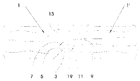
English Abstract


The invention concerns laths (1, 1') with grooved longitudinal edges capable
of being interlocked to form a floor. The invention is characterised in that
the laths comprise on their right a groove (3) arranged substantially
perpendicular to the surface of the lath, comprising an indentation (5) on the
side of the groove opposite to the lateral edge of the lath and parallel
bevels (7, 9) oriented towards said lath edge and arranged more or less at 45
degrees relative to the sides of the groove, which co-operate when installed
with a protuberance (19) of the left of the lath, matching in shape said
groove (3), enabling through the bevels (7, 9) the protuberance (19) to be
inserted at an angle of about 45 degrees into the groove (3) and enabling by
simple pressure to interlock two successive laths.


French Abstract

La présente invention se rapporte à des lattes (1, 1') à bords longitudinaux rainurés pouvant s'emboîter en vue de former un plancher, caractérisées en ce que les lattes comportent sur leur profil droit une rainure (3) pratiquée essentiellement perpendiculairement à la face de la latte, comportant un décrochement (5) sur le côté de la rainure opposé au bord lateral de la latte et des chafreins parallèles (7, 9) dirigés vers ce bord de la latte et disposés approximativement à 45 degrés par rapport aux côtés de la rainure, qui collaborent lors de la pose avec un bossage (19) du profil gauche de la latte, de forme complémentaire à ladite rainure (3), en permettant grâce aux chanfreins (7, 9) l'introduction du bossage (19) sous un angle d'approximativement 45 degrés dans la rainure (3) et permettant par une simple pression d'encliqueter deux lattes successives.

Claims

Note: Claims are shown in the official language in which they were submitted.

CLAIMS
1. Laths (1,1') with grooved longitudinal edges
capable of being interlocked in order to form a floor,
comprising on a longitudinal edge, called right-hand
profile, a groove (3) and on the opposite edge, called
left-hand profile, a protuberance (19) matching in shape said
groove (3), said groove being machined and comprising an
indentation (5) on the side of the groove opposite the
lateral edge of the lath and parallel bevels (7, 9) oriented
toward the edge of said lath and arranged approximately at 45
degrees relative to the sides of the groove, which co-operate
during assembly with the protuberance (19) of the left-hand
profile of the adjacent lath in the use position,
characterised in that said protuberance (19) can be inserted
at an angle of about 45 degrees into the groove (3) by means
of the bevels (7, 9), by simple downwards pressure and
without undue deformation, thus bringing the two successive
laths in a same plane.
2. Laths according to claim 1, characterised in
that the left-hand and right-hand profiles of the laths are
extending upwards of the area comprising said groove (3) in
the shape of an interlocking in complementary steps, ending
in a flat joint without gaps between the top surfaces.

Description

Note: Descriptions are shown in the official language in which they were submitted.


9
CA 02425064 2003-04-07
GROOVED LATHS AND SELF-CATCHING TABS IN PARTICULAR FOR
FORMING FLOORS AND METHOD FOR MACHINING SUCH LATHS
Subject of the invention
[0001] The present invention relates to laths,
i.e_ laths in the proper sense of the word as well as blades
or panels, with grooved and tabbed longitudinal edges that
can easily be interlocked in order to form floors,
panellings, etc.
Technological background and state of the art
[0002] Numerous devices and systems intended to
provide easy laying of floor elements through clip-on
mounting on their respective lateral edges of individual
elements having the shape of laths or blades of any kind
(solid wood, laminated sheets, synthetic materials, etc.) are
already known.
[0003) As an example of the systems meeting this
definition, the following documents may be mentioned.
[0004] Document WO OOj20705 implies the use of a
separate connecting element.
(0005] Document WO 00/20706 equally implies a
connecting element provided with deformable lips.
[0006] Document EP-0 843 763-A describes a
system in which the co-operating coupling elements are
arranged at the level of the edges of both opposing sides of
the laths and which is characterised by incorporated
mechanical locking means.
(0007] German patent application DE-19933343.2
provides for elements forming a spring and penetrating into a
groove of the adjacent plate.
[0008] Other devices of the same type are

10
CA 02425064 2003-04-07
described in these documents. One feature of the various
existing systems without additional connecting elements is
the fact that the clip-on mounting is performed by a
simultaneous forward and rotating movement thus leading to
the mechanical locking.
[0009] Thus, Document DE-U-7928703 presents a
systemthat is similar to the present invention but requires,
however, a rotating movement in order to allow two laths
matching in shape to be anchored together. Simple
interlocking at an angle of about 45 degrees as disclosed in
the present invention is thus not possible.
Aims of this invention
[0009] The present invention particularly aims
to improve the existing assembly techniques, more
particularly to simplify the profiles of the grooves and tabs
made on the laths, especially by reducing the necessary
machining operations while ensuring easy laying and providing
effective locking.
[0010] The present invention especially aims at
a configuration of profiles which allows direct interlocking
through simple, successive pressures of the various laths
without any rotating movement.
[0011] In order to facilitate the machining
operations of the edges of the various .boards, special
attention has been paid to ensure the easiest possible points
of access of the various tools.
[0012] The purpose of this invention is
preferably achieved by simultaneous machining of both
opposing edges (sides) in a limited number of steps, while
allowing at least some of the steps to be easily performed in
a semi-continuous way without having to basically modify the

11
CA 02425064 2003-04-07
position of the machining tools. The invention especially
aims to keep the tools perpendicular to the surface of the
laths for most operations.
Characteristic elements of the invention
[0013] The invention is based on the fact that a
groove essentially perpendicular to the surfaces of the Lath
is made on an edge of the lath with bevels at 45 degrees, and
that, during assembly, this groove co-operates with a
matching element in the shape of a protuberance provided on
the opposite edge of an adjacent lath.
[0014] Other details and additional features of
the invention will be clearer when reading the preferred
embodiment of the invention with reference to the attached
drawings and claims.
Brief description of the figures
[0015] Figure 1 represents a cross-section view
of the edge-to-edge assembly of two successive laths.
[0016] Figures 2, 3 and 4 represent the
right-hand profile of a lath undergoing three successive
machining operations (steps).
[0017] Figures 5 and 6 represent two successive
machining steps for the left-hand profile of a lath.
[0018] In Figures 2 to 6, the shape and the
connection plane of the tools are shown with thick lines,
while the piece being machined is represented by continuous
lines for the final shape, which is intended after the
completion of the various machining steps for the profile in
question.
[0019] The shape of the piece undergoing the
specific machining step is represented with a dotted line.
[0020] In these drawings, the laths are

12 CA 02425064 2003-04-07
conventionally represented in their position as laid to form
a floor. The edge on one side is conventionally called the
right-hand profile and the other edge is called the left-hand
profile .
[0021] These profiles are shaped, i.e. machined,
in such a way that the right-hand profile of one lath can
receive the left-hand profile of the following lath through
traditional clip-on mounting.
Detailed description of the invention
[0022] The essential feature of the assembly
according to the present invention is the fact that the
machining operations are performed in such a way that the
lath, before interlocking into the preceding and already laid
lath, can be brought into a plane that is parallel to its
neighbour and can then be interlocked without undue
deformation through pressure oriented at more or less 45°
degrees downwards by leading the lath that has just been
interlocked onto the same plane and level with the one
previously laid.
[0023] This is made possible since the first
side of lath l, shown on Figures 2 to 4 and in the shape of
the right-hand profile, comprises from bottom to top a groove
3, that is turned upwards and perpendicular to the surfaces
of lath 1 and comprises an indentation 5 on the side opposite
the lateral edge of the lath, this indentation 5 ending in a
bevel 7 turned towards the lateral edge at an angle of
approximately 45 degrees. A bevel 9 that is parallel to the
bevel 7 is provided on the opposite side of groove 3.
[0024] The bevel 9 extends right up to the end
of the edge by a flat surface 11.
[0025] The mentioned indentation 5 is made in

13
CA 02425064 2003-04-07
the body of the lath and extends (upwards) after the bevel 7
with an approximately right-angle cut 12 having in turn a
small indentation 13. Other shapes may be chosen for this top
part.
[0026) The opposite profile, called the
left-hand profile, which is represented for an adjacent lath
in Figure 1, is matching in shape the one previously
described, a protuberance 19 being provided in order to fit
into the groove 3.
[0027] In Figures 2 to 6, the shape of the tools
21, 23, 25, 27 and 29 used for the various steps of the
right-hand and left-hand profiles is shown.
[0028] It should be noted that the working
position of the tools has been shown according to the laying
direction of the lath to form a floor; however, in order to
perform the machining operation, other tool positions may
obviously also be chosen, which means that the piece to be
machined must be set in a position matching the tool.
[0029] It will be noted that, except for the
operation shown on Figure 4, the tools work at a right angle
relative to the top and bottom surfaces of the laths.
[0030] The operation performed on Figure 4 is
the only one achieved at an angle of approximately 45 degrees
relative to the surface of the laths.
[0031] It will also be noted how the number of
operations is particularly reduced, how the shapes of the
tools are relatively simple, and how the different steps can
be performed by means of traditional machinery of the
milling/cutting type.
[0032] Machining can of course be simultaneously
carried out on both edges of the raw lath.
[0033] Additional finishing operations

14
CA 02425064 2003-04-07
(deburring, varnishing, etc.) are of course possible within
the scope of the invention.
[0034] The presence of the bevels 7 and 9 allows
to introduce the protuberance 19 of the left-hand profile of
the lath to be laid, by placing it on a plane parallel to the
right-hand profile of the preceding lath, and the lath is
simply interlocked by pressing along an angle of about 45
degrees.
[0035] As can be seen from the drawings, if the
left-hand profile of the lath 1' is matching in shape the
right-hand profile of the preceding lath 1, some leeway (see
figure 1) must be left in order to facilitate interlocking.
Suitable tolerance is provided in order to allow the easy
introduction of the groove and protuberance in the
approximate position at 45 degrees of the lath to be laid
relative to the preceding lath, and then to allow
interlocking.

Representative Drawing
A single figure which represents the drawing illustrating the invention.
Administrative Status

2024-08-01:As part of the Next Generation Patents (NGP) transition, the Canadian Patents Database (CPD) now contains a more detailed Event History, which replicates the Event Log of our new back-office solution.

Please note that "Inactive:" events refers to events no longer in use in our new back-office solution.

For a clearer understanding of the status of the application/patent presented on this page, the site Disclaimer , as well as the definitions for Patent , Event History , Maintenance Fee  and Payment History  should be consulted.

Event History

Description Date
Application Not Reinstated by Deadline 2006-10-10
Time Limit for Reversal Expired 2006-10-10
Inactive: Abandon-RFE+Late fee unpaid-Correspondence sent 2005-10-11
Deemed Abandoned - Failure to Respond to Maintenance Fee Notice 2005-10-11
Letter Sent 2003-09-17
Inactive: Cover page published 2003-09-12
Inactive: Notice - National entry - No RFE 2003-09-10
Application Received - PCT 2003-05-09
Inactive: Single transfer 2003-05-02
National Entry Requirements Determined Compliant 2003-04-07
Application Published (Open to Public Inspection) 2002-04-18

Abandonment History

Abandonment Date Reason Reinstatement Date
2005-10-11

Maintenance Fee

The last payment was received on 2004-09-21

Note : If the full payment has not been received on or before the date indicated, a further fee may be required which may be one of the following

  • the reinstatement fee;
  • the late payment fee; or
  • additional fee to reverse deemed expiry.

Please refer to the CIPO Patent Fees web page to see all current fee amounts.

Fee History

Fee Type Anniversary Year Due Date Paid Date
Basic national fee - standard 2003-04-07
MF (application, 2nd anniv.) - standard 02 2002-10-10 2003-04-07
Registration of a document 2003-05-02
MF (application, 3rd anniv.) - standard 03 2003-10-10 2003-10-03
MF (application, 4th anniv.) - standard 04 2004-10-12 2004-09-21
Owners on Record

Note: Records showing the ownership history in alphabetical order.

Current Owners on Record
TARKETT SOMMER S.A.
Past Owners on Record
GERARD PFEIFFER
JEAN-PHILIPPE GEORGES
Past Owners that do not appear in the "Owners on Record" listing will appear in other documentation within the application.
Documents

To view selected files, please enter reCAPTCHA code :


To view images, click a link in the Document Description column. To download the documents, select one or more checkboxes in the first column and then click the "Download Selected in PDF format (Zip Archive)" or the "Download Selected as Single PDF" button.

List of published and non-published patent-specific documents on the CPD .

If you have any difficulty accessing content, you can call the Client Service Centre at 1-866-997-1936 or send them an e-mail at CIPO Client Service Centre.


Document
Description 
Date
(yyyy-mm-dd) 
Number of pages   Size of Image (KB) 
Drawings 2003-04-07 3 26
Representative drawing 2003-04-07 1 8
Abstract 2003-04-07 2 83
Claims 2003-04-07 1 31
Description 2003-04-07 6 224
Cover Page 2003-09-12 1 43
Notice of National Entry 2003-09-10 1 189
Courtesy - Certificate of registration (related document(s)) 2003-09-17 1 106
Reminder - Request for Examination 2005-06-13 1 115
Courtesy - Abandonment Letter (Request for Examination) 2005-12-20 1 166
Courtesy - Abandonment Letter (Maintenance Fee) 2005-12-06 1 174
PCT 2003-04-07 14 598
Fees 2003-10-03 1 36
Fees 2004-09-21 1 36