Note: Descriptions are shown in the official language in which they were submitted.
CA 02425677 2003-04-25
WO 02/36442 PCT/CA01/01356
CARTON, METHOD OF FORMING SAME, AND CARTON BLANK
FIELD OF THE INVENTION
This invention relates to a carton blank, a carton, and a method of forming
the carton. The carton design facilitates manufacture of a carton which is
substantially air
tight.
BACKGROUND
Food must generally be packaged in air tight packaging to avoid infestations.
Traditional cereal boxes have four flaps: two end flaps which fold in and are
overlain by an
interior major flap and an outer major flap. Such a box leaves pin hole
openings to its
interior at its corners. Thus, to be suitable to contain food, these cereal
boxes are provided
with an interior air tight bag.
A number of carton designs are known which provide an air tight carton
avoiding the need for an air tight bag. One such carton design is used in many
milk cartons
and is described, in one variation, in US4,211,357 to Lisiecki issued July 8,
1980. The
carton bottom has two major flaps and two end panels which are ears joined
between the
two major flaps. A heat seal adhesive is applied to the ears and one major
flap then the ears
are folded in and the major flaps folded down while the carton sits on a
mandrel. Pressure
and heat is then applied to seal the bottom. The carton top comprises two ears
joined
between two major panels. The two ears are folded in and a heat seal adhesive
applied to
the inside top margin of one of the major panels. The top margins of the major
panels are
then pressed together while heated to seal same. This results in a gable top.
While a gable top carton allows the carton to be sealed after filling, there
is
considerable empty head space in the carton. The gable top also precludes
stacking of the
cartons.
CA 02425677 2003-04-25
WO 02/36442 PCT/CA01/01356
Another carton design, often used for long shelf life storage of juice or
other
liquids, comprises a sleeve with, at its top and bottom, two major panels
which each
terminate in an ear-half at either end. For each pair of major panels, a heat
seal surface is
provided on the inside face of the margin of the major panels. After applying
a heat
sealable material, the pair of major panels is pressed together with heat to
form a fin seal.
This also joins opposed ear-halves; the ears are then folded down and spot
glued to the
carton.
The fin sealed carton makes better use of the interior volume of the carton,
however, re-sealing of such a carton after opening presents difficulties. In
some such
cartons, it is contemplated that the carton is opened by cutting through the
fin seal: in such
case, re-sealing is not possible. In other such cartons, a re-closeable flap
(e.g., a plastic
fitment) may be added to the top of the carton. However, such a flap provides
only a
relatively small access area to the inside of the carton. Thus, while such a
flap may be
adequate for a carton containing a liquid, in many instances it may not be
adequate for a
carton containing dry goods.
Both gable top and fin seal cartons require application of pressure from
opposite sides to seal the carton top, as well as the presence of a heat
sealable material.
This increases the difficulty of manufacturing such cartons.
US6,056,6~0 issued May 2, 2000 to Spronk-Dik describes an airtight carton
which requires the adhesion of a separate material strip to the carton blank.
Accordingly, a need remains for a carton which is capable of providing an air
tight seal, may provide efficient use of the interior volume of the carton,
may be stackable,
and may be readily manufactured.
SUMMARY OF THE INVENTION
The top of a carton, with opposite main panels and opposite side panels, has
an inner and outer major flap hinged to_opposite main panels. At each side
panel, an ear has-
_2_
CA 02425677 2003-04-25
WO 02/36442 PCT/CA01/01356
a lower portion hinged to the side panel and two upper ear-halves, one hinged
to each of the
major flaps. To seal the top, adhesive is applied to an outer face of the
inner major flap and
to the ear-halves extending from either end of one of the major flaps, usually
the inner
major flap. Then the inner major flap is folded down and the ear-halves
extending
therefrom are folded down and out. The outer major flap with extending ear-
halves is
folded on top in overlapping relation so that the adhesive bonds. In one
aspect, each ear has
a notch between the ear-halves to facilitate overlapping of the ear-halves.
Accordingly, the present invention provides a carton comprising: a first main
panel; a second main panel; a pair of opposed side panels hinged between said
main panels;
an inner major flap extending along said first main panel and hinged thereto;
an outer major
flap extending along said second main panel and hinged thereto, said outer
major flap
having a width so as to provide an overlapping portion along its length with
said inner
major flap; a pair of opposed outwardly projecting ears, each ear having a
lower ear portion
extending from a top of one of said side panels, an upper .ear-half extending
from an end of
said inner major flap and an upper ear-half extending from an end of said
outer major flap,
one upper ear-half of a given ear having a width so as to provide an
overlapping portion
along its length with another upper ear-half of said given ear; an adhesive
bond between an
inside face of said outer major flap and an outside face of said inner major
flap along said
overlapping portion of said flaps and between an inside face of said one,
overlapping, upper
ear-half and an outside face of said another upper ear-half of each ear along
said
overlapping portion of said ear halves.
According to another aspect of the present invention, there is provided a
carton blank, comprising: a first main panel; a second main panel; a medial
side panel
hinged to said first main panel at a hinge line and to said second main panel
at a hinge line;
a first major flap hinged to said first main panel at a hinge line; a second
major flap hinged
to said second main panel at a hinge Line; a medial ear panel hinged to said
medial side
panel at a hinge line, hinged to said first major flap at a hinge line and
hinged to said second
major flap at a hinge line, said medial ear panel having a free edge opposite
said hinge line
between said medial side panel and said medial ear panel, said free edge
having a notch.
-3-
CA 02425677 2003-04-25
WO 02/36442 PCT/CA01/01356
According to a further aspect of the invention, there is provided a method of
forming a carton, comprising:
(a) folding and gluing closed a bottom of said carton; .
(b) at a top of said carton having a first major flap hinged to a first main
panel of said
carton, a second major flap hinged to a second main panel of said carton, two
ears each
having a lower portion hinged to one of two side panels, a first upper ear-
half hinged to said
first major flap, and a second upper ear-half hinged to said second major
flap, folding down
said first major flap and folding down and out said first upper ear-half of
each of said ears;
(c) applying adhesive to an outside face of said first major flap and to an
outside face of
said first upper ear-half of each said ear either before or after (b);
(d) folding down said second major flap and folding down and out said second
upper
ear-half of each said ear so that said second major flap overlaps said first
major flap and
said second upper ear-half of each said ear overlaps said first upper ear-half
of each said ear
and said adhesive bonds said second major flap to said first major flap and
said second
upper ear-half of each said ear to said first upper ear-half of each said ear.
Other aspects of the invention will become apparent after a review of the
following description and drawings.
BRIEF DESCRIPTION OF THE DRAWINGS
In the figures which illustrate an embodiment of the invention,
figure 1 is a perspective view of a carton,
figure 2 is a perspective view of a carton blank from which the carton of
figure 1 may be
manufactured,
figures 3 to 8 are perspective views illustrating the manufacture of the
carton from the blank
of figure 2,
figures 9 to 13 are perspective views illustrating opening and re-closing of
the carton of
figure 1, and
figure 14 is a perspective view of a re-closed carton.
-4-
CA 02425677 2003-04-25
WO 02/36442 PCT/CA01/01356
DETAILED DESCRIPTION OF THE PREFERRED EMBODIMENTS
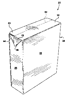
Turning to figures 1 and 7, a carton 20 has two main panels 22 and 24 with a
pair of side panels 26 and 28 hinged therebetween. At the top of the carton,
an inner major
flap 34 is hinged to main panel 24 and an outer major flap 32 is hinged to
panel 22. An ear
36, 38 projects outwardly from each end of the major flaps 32, 34 and is glued
down to a
side panel 26, 28. Each ear has a lower ear portion 40 hinged to the top of a
side panel and
two upper ear-halves 42, 44, one upper ear-half hinged to each of the major
flaps 32, 34.
The outer major flap 32 overlaps the inner major flap 34 and the upper ear-
halves 42 extending from the outer major flap 32 overlap the respective upper
ear-halves 44
extending from the inner major flap 34. There is an adhesive bond along this
overlapping
portion between an inside face of the outer major flap 32 and its upper ear-
halves 42 on the
one hand and the outside face of the inner major flap 34 and its upper ear-
halves 44 on the
other. Each ear 36, 38 is bonded to its respective side panel 26, 28.
With reference to figures 6 and 7, it is noted that the bottom of the carton
is
similarly configured with an inner major flap 134 and respective upper ear-
halves 144
overlapped by, and bonded to, an outer major flap 132 and respective upper ear-
halves 142.
However, at the carton bottom, the ears 136, 138 are shown bonded to the outer
major panel
132. Alternatively, eaxs 136, 138 could also be bonded to their side panels
26, 28.
Returning to figures 1 and 7, and also referencing figure 2, which shows a
carton blank 50 from which carton 20 is manufactured, a weakened line 54
extends along
the inner major flap 34 and weakened lines 64a, 64b extend along each of upper
ear-halves
44. The weakened lines 54, 64a, 64b are aligned so as to form one continuous
weakened
line in the completed carton. These weakened lines may be cut scores, lines of
perforation,
or the like. These weakened lines define a marginal portion 55 along which the
adhesive
bond extends.
Each side panel 26, 28 has a weakened line 56, 58 formed as a closed
(circular) shape 66. This weakened line extends from the outside face of the
carton 20 to a
depth which is less than the thickness of each side panel. (This depth may be
50% of the
-5-
CA 02425677 2003-04-25
WO 02/36442 PCT/CA01/01356
thickness of the side panels.) The adhesive bond between the ears 36, 38 and
their
respective side panels 26, 28 extends within this closed shape 66.
The outer major flap 32 has a medial fold line 62 which overlies the inner
major flap 34 weakened line 54. The medial fold line 62 defines a flap end
portion 63 of
outer major flap 34.
With particular reference to figure 2, in the carton blank 50, each ear 36, 38
has a free edge 74 with a notch 76; this notch facilitates overlapping of the
upper ear-halves.
A fold line 78a extends in ear 38 from a top corner of main panel 24 to notch
76. A second
fold line 80a extends in ear 38 from a top corner of main panel 22 to the
notch 76. Similar
fold lines 78b and 80b extend in ear 36, however, fold line 80b extends from a
top corner of
margin strip 84 defined by hinge line 86. It will also be noted that eaxs 136
and 138 at the
bottom of the carton blank have similar notches 176 and fold lines 178a, 178b,
180a, 180b.
Carton blank 50 also shows hinge line 88 between main panel 24 and side
panel 28; hinge line 90 between main panel 22 and side panel 28; and hinge
line 92 between
main panel 22 and side panel 26. Additionally is shown: a hinge line 94
between main
panel 24 and inner major flap 34; hinge line 96 between side panel 28 and ear
38; hinge line
98 between main panel 22 and outer major flap 32; hinge line 99 between side
panel 26 and
ear 36; and similar hinge lines 194, 196, 198, and 199 at the bottom of the
blank.
Note that a fold line may be structurally indistinguishable from a hinge line;
the two terms were herein merely to indicate a different function.
To adapt the carton blank 50 for use with foods, an air impermeable coating
should be applied to the interior face of the blank.
To manufacture a carton 20 of figure 1 from a carton blank 50 of figure 2,
adhesive is to applied one or both of the outside face of margin strip 84 and
the inside face
of a margin of main panel 24 and inner major flap 34. The carton is formed
into a sleeve as
illustrated in the sequence of figures 3 to 5 with the margin strip 84 bonded
to the margin of
main panel 24 and inner major flap 34 by the applied adhesive. Next, the
bottom inner
-6-
CA 02425677 2003-04-25
WO 02/36442 PCT/CA01/01356
major flap 134 is folded down and its attached ear-halves 144 are folded down
and out.
Adhesive is applied to either or both of the margin of the outside face of the
inner major
flap 134 and its ear-halves 144 or to the inside face of the outer major flap
132 and its ear-
halves 142. The outer major flap and its ear-halves 142 are then folded over,
and bonded to,
the inner major flap 134 with its ear-halves 144, as seen in figure 6. The
notches in the ear-
halves permit one ear-half to be folded over the other without interference.
With the ear-halves 144 folded down and out, inner major flap 134 is
supported at either of its ends by the bottom edge of side panels 26, 28. This
sufficiently
10' supports the inner major flap so that the outer major flap may be pressed
thereagainst to
bond the two in the absence of a mandrel behind the inner major flap. Thus, a
mandrel is
optional. Also, in consequence of the self supporting inner flap, a hot melt
adhesive may be
employed as the applied adhesive.
Next adhesive is applied to the outside face of outer major flap 132 and the
ears 136, 138 are folded axound and bonded to the outer major flap 132, as
seen in figure 6.
This completes the bottom of the carton.
The carton with its completed bottom may then be filled. After filling, the
top inner major flap 34 is folded down and its attached ear-halves 44 are
folded down and
out. This is shown, progressively, in figures 7 and 8. As seen in figure 8,
this results in the
top edge of side panels 26, 28 supporting the ends of the inner major flap 34.
Adhesive
(which may be hot melt) is applied to either or both of the margin of the
outside face of the
inner major flap 34 and its ear-halves 44 or to the inside face of the outer
major flap 32
inwaxdly from fold line 62 and to the margins of its ear-halves 42. The outer
major flap and
its ear-halves 142 are then folded over, and bonded to, the inner major flap
134 with its ear-
halves 144, as seen in figure 9. Lastly, a spot of adhesive may be applied in
each closed
shape 66 of side panels 26, 28 and each (now bonded) ear 36, 38 may be folded
down and
bonded to its respective side panel, also as seen in figure 9..
It will be apparent that with a line of adhesive forming a bond from ear-to-
ear at both the top and bottom of the carton 20, there are no pin hole
openings to the interior
CA 02425677 2003-04-25
WO 02/36442 PCT/CA01/01356
of the carton. Thus, at least where the carton has an air impermeable coating,
the carton is
air tight. Consequently, carton 20 may be used as a bagless cereal box.
To open carton 20, ears 36, 38 are grasped and pulled away from side panels
26, 28, as seen in figure 10. The weakened lines 56, 58 in the side panels
which extend to a
depth which is less than the thickness of the side panels facilitate this.
More particularly, it
is not necessary for the adhesive bond between the ears and side panels to be
broken as
carton material within closed shapes 66 simply pulls away with the ears.
Because the
weakened lines 56, 58 do not extend to the depth of the side panels, the
carton remains
impermeable to air even after the ears are pulled away.
Next, the outside margin of the outer major flap 32 may be grasped and
pulled back; as shown in figure 11. This causes the weakened lines 54, 64a,
64b to give
way resulting in a tear strip 210 (which previously was the marginal portion
55 of the inner
maj or flap and its ear-halves 44) pulling away with the outer maj or flap 32.
Thus, again, it
is not necessary to break the adhesive bond between the outer and inner major
flaps, nor
between their respective ear-halves. After the outer major flap has been
pulled back, the
interior of the carton.may be accessed.
To re-close the carton, the ears 36, 38 may be folded inwardly, as seen in
figure 12. Next the inner major flap may be folded downwardly over top of the
lower ear
portions 40 of each ear. Then the outer major flap 34 may be bent at its fold
line 62. Flap
end portion 63 of outer major flap 32 is then inserted between inner major
flap 34 and the
upper ear-halves 44 which extend from the inner major flap, as seen in figure
12. Once the
carton is fully re-closed, as seen in figures 13 and 14, the outer major flap
end portion 63
underlies the inner major flap 34.
Optionally, the inner and outer major flaps 132, 134 may be embossed so
that the ears 136, 138 are more flush with the bottom of carton 20.
Alternatively, the
bottom ears 136, 138 may be folded around and glued to side panels 26, 28,
rather than
being folded around and glued to outer major flap 132.
_g_
CA 02425677 2003-04-25
WO 02/36442 PCT/CA01/01356
Other modifications will be apparent to those skilled in the art and,
therefore,
the invention is defined in the claims.
-9-