Language selection

Search

Patent 2425895 Summary

Third-party information liability

Some of the information on this Web page has been provided by external sources. The Government of Canada is not responsible for the accuracy, reliability or currency of the information supplied by external sources. Users wishing to rely upon this information should consult directly with the source of the information. Content provided by external sources is not subject to official languages, privacy and accessibility requirements.

Claims and Abstract availability

Any discrepancies in the text and image of the Claims and Abstract are due to differing posting times. Text of the Claims and Abstract are posted:

  • At the time the application is open to public inspection;
  • At the time of issue of the patent (grant).
(12) Patent: (11) CA 2425895
(54) English Title: PROCESS FOR DRILLING HOLES IN A METALLIC WORKPIECE HAVING A THERMAL BARRIER COATING
(54) French Title: PROCEDE DE PERCAGE DE TROUS DANS UNE PIECE A TRAVAILLER METALLIQUE POSSEDANT UN REVETEMENT D'ISOLEMENT THERMIQUE
Status: Deemed expired
Bibliographic Data
(51) International Patent Classification (IPC):
  • B23K 26/382 (2014.01)
  • F01D 25/08 (2006.01)
(72) Inventors :
  • LORINGER, GARY (United States of America)
(73) Owners :
  • TURBOCOMBUSTOR TECHNOLOGY, INC. (United States of America)
(71) Applicants :
  • CHROMALLOY GAS TURBINE CORPORATION (United States of America)
(74) Agent: DEETH WILLIAMS WALL LLP
(74) Associate agent:
(45) Issued: 2007-04-24
(86) PCT Filing Date: 2001-10-03
(87) Open to Public Inspection: 2002-04-25
Examination requested: 2003-12-19
Availability of licence: N/A
(25) Language of filing: English

Patent Cooperation Treaty (PCT): Yes
(86) PCT Filing Number: PCT/US2001/030873
(87) International Publication Number: WO2002/032614
(85) National Entry: 2003-04-15

(30) Application Priority Data:
Application No. Country/Territory Date
09/691,767 United States of America 2000-10-18

Abstracts

English Abstract


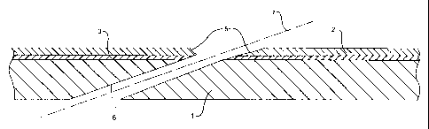
A method is provided for drilling a hole through a metallic workpiece (1)
having a thermal barrier coating (3) with a ceramic top coat (2) by laser
drilling a counterbore to a depth which extends through the ceramic top coat
but not substantially into the metallic workpiece and then laser drilling the
hole through the workpiece aligned with the counterbore, the counterbore
having a diameter larger than the hole.


French Abstract

L'invention concerne un procédé de perçage d'un trou à travers une pièce à travailler métallique (1) comportant un revêtement d'isolement thermique (3) avec une couche de finition en céramique (3). Ce procédé consiste à percer par laser un contre-alésage à une profondeur allant jusqu'à la couche de finition en céramique, mais sensiblement pas dans la pièce à travailler, puis à percer par laser à travers la pièce à travailler alignée avec le contre-alésage, ce dernier possédant un diamètre supérieur au trou.

Claims

Note: Claims are shown in the official language in which they were submitted.


-10-


What is claimed is:

1. A method of drilling a hole into a metallic
workpiece having a thermal barrier coating with a
ceramic top coat comprising:
laser drilling a counterbore to a depth which
extends through the ceramic top coat but not
substantially into the metallic workpiece; and
then laser drilling the hole through the
workpiece aligned with the counterbore, the counterbore
having a diameter larger than the hole.

2. Method of Claim 1 wherein the metallic
workpiece is a gas turbine combustion liner and the
holes are cooling holes.

3. Method of Claim 2 wherein the counterbore and
hole are drilled by percussion drilling.

4. Method of Claim 2 wherein the counterbore and
hole are drilled by a Laser-on-the-Fly process.

5. Method of Claim 1 wherein the thermal barrier
coating further comprises a bond coat bonding the
ceramic top coat to the metallic workpiece.

6. Method of Claim 2 wherein the metallic
workpiece comprises a stainless steel alloy.

7. Method of Claim 2 wherein the counterbore and
cooling holes are drilled at an angle of 17 to 25
degrees to a surface of the workpiece.

8. Method of Claim 5 wherein the diameter of the
counterbore is from about 50% to 150% larger than the
diameter of the hole.


-11-


9. Method of Claim 8 wherein the counterbore
extends into the bond coat.

10. Method of Claim 9 wherein the counterbore has
a curved surface.

11. Method of Claim 10 wherein the ceramic top
coat is a yttria stabilized zirconia.

12. Method of Claim 11 wherein the bond coat is
selected from the group consisting of MCrAlY wherein M
is Ni, Co, Fe or a combination of Ni and Co, platinum
aluminide and aluminide.


Description

Note: Descriptions are shown in the official language in which they were submitted.


CA 02425895 2003-04-15
WO 02/32614 PCT/USO1/30873
PROCESS FOR DRILLING HOLES IN A METALLIC
WORKPIECE HAVING A THERMAL BARRIER
COATING
Background of The Invention
A combustion liner which is used in an aerospace
application or in a land based turbine application will
have a series of laser drilled holes drilled at an
angle to produce a cooling effect during operation.
The laser drilled cooling holes are called effusion
holes. A typical component will have several thousand
effusion holes in order to facilitate the proper
cooling pattern. Effusion holes are characteristically
drilled at very steep angles (see Figures) to the
surface of the component (eg. 17° - 25°) . These
effusion holes can be laser drilled by three different
processes: trepan; percussion drilling; or Laser-on-
the-Fly. The trepan method of laser drilling, which
pierces the material with a focused beam, then
traverses around the hole circumference to produce the
hole, is by far the most time consuming. A trepanned
laser hole can take from 8 to 12 seconds per hole,
dependent on material thickness and angle of entry.
The percussion method of laser drilling uses a
defocused laser beam to produce the hole by employing a
series of pulsed laser shots into the metal until the
hole has fully been produced. A percussion drilled
hole can take from 1 to S seconds per hole, dependent


CA 02425895 2003-04-15
WO 02/32614 PCT/USO1/30873
- 2 -
on material thickness and angle of entry. The Laser-
on-the-Fly method of laser dxi112ng uses a defocused
laser beam, while synchronizing the speed of a rotary
device and the pulsing of the laser, to drill a
plurality of holes during the rotation cycle one pulse
at a time (see US Patent 6130405). A hole produced by
the Laser-on-the-Fly method can take from .3 to 2
seconds per hole, dependent on material thickness and
angle of entry.
The typical material that is used to produce a
combustor liner ~s a high temperature stainless steel
alloy with a melting point of approximately 2400°F.
Design engineers, in order to enhance the life
expectancy of these components, have added to the
component a layer of thermal barrier coating (TBC)
having a ceramic top coat. As shown in the Figures,
the TBC generally comprises a bond coat 3 to bond the
ceramic top coat 2 to the metallic substrate 1. The
bond coat can be an MCrAlY bond coat where M is Ni, Co
or Fe or a combination of Co and Ni; an aluminide bond
coat; or a platinum aluminide bond coat. The ceramic
based top coat can be, for example, a zironia
stabilized with yttria. The MCrAIY bond coat can be
applied by various processes including plasma spraying,
electron beam physical vapor deposition or sputtering,
while the ceramic top coat can be applied by various
processed including plasma spraying, electron beam
physical vapor deposition, sputtering and chemical


CA 02425895 2003-04-15
WO 02/32614 PCT/USO1/30873
- 3 -
vapor deposition. The ceramic top coat has a high
melting point of, for example, 4500°F.
The addition of this thermal barrier coating,
while improving component life and engine performance,
has created a problem for the laser drilling operation.
When laser drilling through the ceramic coating into
the base metal as shown in Figure 4 a large area of
recast 4 is created at the intersection of the base
metal of the substrate and the thermal barrier coating.
This area of recast has been measured up to 0.024
inches thick. The design specifications for combustion
liners of several Original Equipment Manufacturers
(OEM) have set the maximum allowable recast level at
0.004 inches thick. A recast layer higher than the
acceptable limits is detrimental to the life of the
component, since a stress crack can ultimately be
produced from the recast layer. The pocket of recast
is a direct result of the laser's interaction where the
TBC meets the base metal. Since the base metal has a
melting point of 2400°F, far less than the 4500°F of the
ceramic top coat, the molten material has a tendency to
create a small pocket at the joining point (see Figure
3). When employing the percussion or Laser-on-the-Fly
drilling method, the pocket is created between the
first and second pulses. During the subsequent laser
pulses, that are required to fully produce the hole,
the molten material is being expelled outward. As the
material is being expelled outward, a portion of molten


CA 02425895 2003-04-15
WO 02/32614 PCT/USO1/30873
- 4 -
material is being redeposited into the pocket that was
created. The solidifying of this material in the
pocket forms the "bubble" of recast 4 (see Figure 4).
Many different parameter settings and gas assist
combinations were tried to reduce the recast "bubble"
The results were similar with all of the combinations
that were tested with the recast "bubble" clearly
present. When employing the trepan method of laser
drilling, the recast "bubble" was eliminated as the
laser beam traversed around the circumference.
However, due to the extremely long cycle times that
would be required to produce the components with the
trepan method, this was not an acceptable solution.
Brief Description of the Drawings
The present invention will be more fully described
by way of example with reference to the accompanying
drawings in which:
Figure 1 is a schematic diagram showing the
workpiece with a counterbore drilled therein;
Figure 2 is a schematic diagram showing the
workpiece with a hole drilled according to the present
invention; and
Figure 3 is an auxiliary view taken looking down
the centerline 7 of the hole 6 of Figure 2.
Figure 4 is a schematic diagram showing the
workpiece with a hole drilled in accordance with the
prior art.


CA 02425895 2003-04-15
WO 02/32614 PCT/USO1/30873
-
Figure 5 is an auxiliary view taken looking down
the centerline 7 of the hole 6 of Figure 4.
Summary of the Tnvention
A method is provided for drilling a hole through a
metallic workpiece having a thermal barrier coating
with a ceramic top coat by laser drilling a counterbore
to a depth which extends through the ceramic top coat
but not substantially into the metallic workpiece and
then laser drilling the hole through the workpiece
aligned with the counterbore, the counterbore having a
diameter larger than the hole.
Detailed Description of the Tnvention
Laser drilling (employing both percussion and
Laser-on--the-Fly (LOF) processes) of aerospace
components, that have previously been coated with a
thermal barrier coating (TBC), produces a pocket of
laser recast which can range up to 0.024 inches thick.
The process of this invention significantly reduces or
eliminates the pocket of laser recast by using the
laser beam to produce a counterbore into the thermal
barrier coating prior to drilling the effusion cooling
hole.
This process allows hole drilling to be carried
out through a metallic workpiece having a thermal
barrier coating with a ceramic top coat. While
specific examples are provided with regard to gas
turbine combustion liners comprised of a stainless
steel alloy (eg. GTD 222, Haynes 188 or AMS 5878),


CA 02425895 2003-04-15
WO 02/32614 PCT/USO1/30873
- 6 -
other gas turbine components can be drilled by this
process as well including, for example, turbine blades
and vanes, and exhaust discharge nozzles. Workpieces
comprised of other alloys can also benefit from this
process, including nickel or cobalt base superalloys.
As shown in the Figures, the thermal barrier coating on
the workpiece generally comprises a bond coat 3 to bond
the ceramic top coat 2 to the metallic substrate 1 and
can comprise bond coat and ceramic top coat
compositions which are applied by processes as is known
in the art. Typically the thickness of the TBC for a
combustion liner can be from about 0.003 to 0.010
inches for the bond coat and about 0.009 to 0.020
inches for the ceramic top coat.
When drilling the holes a counterbore 5 is first
laser drilled (see Figure 1). The counterbore 5 is a
hole which is bored that is larger in diameter than the
primary hole 6, but concentric or aligned therewith.
The counterbore 5 produced by laser drilling exhibits a
curved or radiused surface as shown in-Figure 1. The
diameter of the counterbore 5 is larger than the hole 6
to be drilled to avoid formation of the recast "bubble"
during drilling of the hole 6. The counterbore 5
extends or penetrates through the ceramic top coat 2,
but not substantially into the metallic substrate 1.
Typically the counterbore 5 will extend into the bond
coat 3, with the bond coat acting as a buffer layer
preventing damage to the metallic substrate 1 during

CA 02425895 2006-03-22
_ 7 _
the drilling of the counterbore. The counterbore
diameter will generally be about 50 to 250e larger than
the hole diameter, preferably about 75 to 225% larger.
Typically, for a cooling hole 6 fox a combustion liner,
the hole diameter is from about 0.019 to 0.024 inches,
while the counterbore diameter is from about 0.040 to
0.050 inches.
After drilling the counterbore 5 the hole 6 is
laser drilled aligned with the counterbore (see Figure
2). Since the counterbore is larger than the hole,
formation of a recast bubble at the intersection of the
TBC and substrate is either significantly reduced ox
avoided.
Example
A cylindrical high temperature stainless steel
alloy (AMS 5878) combustor liner was coated with a
thermal barrier coating ~TBC) comprising 0.003 to 0.008
TM
inches of a NiCrAlY (MetCO~ Amdry 964) bond coat and
0.009 to 0.014 inches of a yttria stabilized zirconia
MetCO~ 204 NS) ceramic top coat applied by plasma
spraying. The combustion liner requiring a series of
effusion cooling holes was fixtured to a rotary device.
The rotary device was part of a laser machining center
that was controlled by CNC controlled device and was
coupled with a pulsed ND:YAC Laser. The laser method
of drilled can be either percussion drilling or Laser-
on-the-Fly, dependent on the hole pattern design. The

CA 02425895 2006-03-22
_ g _
side of the component with the TBC was the entrance
side of the effusion hole.
The laser head was set to the required entry angle
of the effusion hole (20°). The laser head was
defocused the determined amount to produce a 0.040 inch
diameter counterbore for a 0.020 inch diameter effusion
hole. A Lumonics JK-704 ND:YAG Laser was used and set
up in the LD1 mode of operation with a 200mm focus
lens. The initial counterbore operation used an assist
gas of compressed air. By defocusing approximately
.500 of an inch with two laser pulses, the desired
diameter (0.040 inches) and depth (0.010 to 0.015
inches) of the counterbore was produced penetrating the
ceramic top coat and into the bond coat layer, but not
into the substrate. A counterbore 5 as shown in Figure
1 was formed. The laser drilling was carried out to
remove only the ceramic top coat to a larger diameter
than the effusion hole. After the entire row of holes
with the counterbore settings was completed, the laser
head was then defocused back to the determined position
to produce the desired effusion cooling hole diameter
of 0.020 inches. The assist gas for the effusion hole
drilling operation was oxygen. The effusion holes were
then drilled in alignment with the counterbore by
either percussion or Laser-on-the-Fly laser drilling
processes. The effusion cooling holes produced had a
reduced layer of recast of about 0.001 to 0.002 inches
thick.


CA 02425895 2003-04-15
WO 02/32614 PCT/USO1/30873
_ g _
A comparative effusion cooling hole drilling
operation carried out without the counterbore produced
a bubble of recast layer of about 0.010 to 0.020 inches
thick and about 0.050 inches long.

Representative Drawing
A single figure which represents the drawing illustrating the invention.
Administrative Status

For a clearer understanding of the status of the application/patent presented on this page, the site Disclaimer , as well as the definitions for Patent , Administrative Status , Maintenance Fee  and Payment History  should be consulted.

Administrative Status

Title Date
Forecasted Issue Date 2007-04-24
(86) PCT Filing Date 2001-10-03
(87) PCT Publication Date 2002-04-25
(85) National Entry 2003-04-15
Examination Requested 2003-12-19
(45) Issued 2007-04-24
Deemed Expired 2016-10-03

Abandonment History

There is no abandonment history.

Payment History

Fee Type Anniversary Year Due Date Amount Paid Paid Date
Application Fee $300.00 2003-04-15
Registration of a document - section 124 $100.00 2003-08-29
Maintenance Fee - Application - New Act 2 2003-10-03 $100.00 2003-09-30
Request for Examination $400.00 2003-12-19
Maintenance Fee - Application - New Act 3 2004-10-04 $100.00 2004-10-01
Registration of a document - section 124 $100.00 2004-11-05
Maintenance Fee - Application - New Act 4 2005-10-03 $100.00 2005-09-29
Maintenance Fee - Application - New Act 5 2006-10-03 $200.00 2006-09-26
Final Fee $300.00 2007-02-05
Maintenance Fee - Patent - New Act 6 2007-10-03 $200.00 2007-09-21
Maintenance Fee - Patent - New Act 7 2008-10-03 $200.00 2008-09-17
Maintenance Fee - Patent - New Act 8 2009-10-05 $200.00 2009-09-17
Maintenance Fee - Patent - New Act 9 2010-10-04 $200.00 2010-09-17
Maintenance Fee - Patent - New Act 10 2011-10-03 $250.00 2011-09-22
Maintenance Fee - Patent - New Act 11 2012-10-03 $250.00 2012-09-27
Maintenance Fee - Patent - New Act 12 2013-10-03 $250.00 2013-09-20
Maintenance Fee - Patent - New Act 13 2014-10-03 $250.00 2014-09-22
Owners on Record

Note: Records showing the ownership history in alphabetical order.

Current Owners on Record
TURBOCOMBUSTOR TECHNOLOGY, INC.
Past Owners on Record
CHROMALLOY GAS TURBINE CORPORATION
LORINGER, GARY
TCT ACQUISITION, INC.
TURBOCOMBUSTER TECHNOLOGY, INC.
Past Owners that do not appear in the "Owners on Record" listing will appear in other documentation within the application.
Documents

To view selected files, please enter reCAPTCHA code :


To view images, click a link in the Document Description column. To download the documents, select one or more checkboxes in the first column and then click the "Download Selected in PDF format (Zip Archive)" or the "Download Selected as Single PDF" button.

List of published and non-published patent-specific documents on the CPD .

If you have any difficulty accessing content, you can call the Client Service Centre at 1-866-997-1936 or send them an e-mail at CIPO Client Service Centre.


Document
Description 
Date
(yyyy-mm-dd) 
Number of pages   Size of Image (KB) 
Representative Drawing 2007-04-10 1 9
Cover Page 2007-04-10 1 39
Abstract 2003-04-15 1 54
Claims 2003-04-15 2 45
Drawings 2003-04-15 3 45
Description 2003-04-15 9 301
Representative Drawing 2003-04-15 1 14
Cover Page 2003-06-18 1 37
Description 2006-03-22 9 292
Drawings 2006-03-22 3 44
PCT 2003-04-15 5 245
Assignment 2003-04-15 3 93
Correspondence 2003-06-16 1 25
Assignment 2003-08-29 2 82
Fees 2003-09-30 1 36
Prosecution-Amendment 2003-12-19 1 33
Correspondence 2004-10-01 1 15
Fees 2004-10-01 1 37
Assignment 2004-11-05 29 922
Correspondence 2005-09-29 1 34
Prosecution-Amendment 2005-11-22 2 36
Prosecution-Amendment 2006-03-22 5 126
Fees 2006-09-26 1 33
Correspondence 2007-02-05 1 34