Note: Descriptions are shown in the official language in which they were submitted.
CA 02426017 2003-04-14
WO 02/48453 PCT/SE01/02750
FABRIC DEWATERING DEVICE AND METHOD
FIELD OF THE INVENTION
The present invention relates to fabric dewatering devices, and more
specifically to the dewatering of continuously moving fabrics used in
papermaking
machines, wherein the fabric is guided through a small-radius turn which
causes
water to be expelled from the fabric via centrifugal force.
BACKGROUND OF THE INVENTION
Permeable fabrics, or belts, are often used in paper machines for supporting
a paper web during the papermaking process. After the web is separated from
the
fabric, the fabric typically undergoes a partial or full-width cleaning or
washing
process. During the cleaning process, the fabric is exposed to water which the
fabric tends to retain when it returns to receive a new portion of the paper
web.
Papermaking applications that involve a process of thermal drying of the paper
web supported on a drying fabric are sensitive to the quantity of residual
water
retained by the fabric, since retained water may rewet the paper web. Thus,
such
drying fabrics must be treated to remove all, or at least a major part of, the
residual
water after cleaning. Other applications may also require fabrics to be at
least
partially dewatered to prevent the water from slinging onto other parts of the
machinery or other parts of the paper web while the fabric is returning from
the
cleaning process to receive a new portion of the paper web.
Tissue paper production requires special types of fabrics to achieve a final
product with a high bulk. Very often TAD fabrics, or other types of tissue-
making
fabrics or belts, are used for the manufacture of textured tissue or web. This
requires a special textured structure of the fabric itself and, consequently,
a definite
fabric thickness. Thick, structured fabrics are especially prone to water
absorption
-1-
CA 02426017 2003-04-14
WO 02/48453 PCT/SE01/02750
during washing and retention of that water in the deeper parts of the fabric
structure.
Pressing is a conventional means of dewatering fabrics that tends to be
effective for non-woven fabrics such as felt. However, pressing is not as
effective
for simple woven fabrics such as those used for forming or TAD applications.
Such woven fabrics are prone to retain water due to their thickness and less
compressible structure.
A roll press for squeezing water from a papermaking felt is disclosed in
Great Britain Patent No. 1,273,827 ('827). The press has two press rolls with
parallel axes and an intermediate roller which is of substantially smaller
diameter
than that of either press roll. The intermediate roll is located between the
two press
rolls so as to form two press nips with the respective press rolls. The
intermediate
roll is arranged offset to one side of the common axial plane of the two press
rolls
and is movable toward this common axial plane. The felt runs into the first
nip
from the side of the common axial plane remote from the intermediate roll and
leaves the second nip towards the remote side. Tension in the felt draws the
intermediate roll against the press rolls with sufficient linear pressure to
compress
the felt so as to squeeze water from the felt.
Vacuum pans are well known in the art for dewatering fabrics and consist
of a collection pan connected to a vacuum source and in proximity to the
travelling
fabric. The vacuum source exerts a suction pressure on the fabric, drawing
water
out of the fabric and into the pan. Another well-known method is to use an air
knife that blows air out a narrow slot and through the fabric, thus blowing
water
out of the fabric and into a collection pan. U.S. Patent No. 4,116,762 to
Gardiner
('762) teaches the use of a hollow, foraminous cylinder over which a felt is
passed.
The cylinder allows air flow through to the travelling felt to drive water out
of the
felt. For fabrics that are very permeable, methods such as the ones described
above involving blowing or sucking air through the fabric require a very large
air
flow and flow velocity, and hence consume a great deal of energy.
Centrifugal force has been used to aid in the dewatering of fabrics by
running the felt over a curved surface with a small radius at high speeds. The
'827
and '762 patents use centrifugal force to aid dewatering to a certain extent.
As
-2-
CA 02426017 2003-04-14
WO 02/48453 PCT/SE01/02750
another example, U.S. Patent No. 6,153,056 to Schiel ('056) discloses a
draining
device that drains water by circulating a press felt loop about a short region
of
convex curvature on a guide roll. The centrifugal force displaces water out of
the
belt and into a collecting device.
Whenever a wet moving fabric changes direction, by passing around a roll
or foil for instance, there is a tendency to throw off water. The magnitude of
this
tendency depends both on the angular velocity and duration for which this is
maintained. A small radius and a large wrap angle will tend to maximize the
water
removal tendency. In the case of a lead roll, a small radius is difficult to
achieve,
especially when combined with a large wrap due to problems with roll
deflection
and critical speeds. Therefore, in the case of a lead roll a small radius is
not
practical, although a large wrap presents no difficulty. In the case of a foil
or
stationary element, a small radius can readily be achieved but the wrap must
be
severely limited in order to avoid fabric wear. .
SUMMARY OF THE INVENTION
The present invention meets these and other needs, and is characterized by
a fabric dewatering device and method in which a fabric to be dewatered is
passed
over a leading guide roll and a trailing guide roll. The leading guide roll is
rotatable about its axis and the trailing guide roll is rotatable about its
axis and is
parallel to the axis of the leading guide roll. The leading and trailing guide
rolls
are spaced apart such that the fabric passes over a portion of a circumference
of the
leading guide roll and then over a portion of the circumference of the
trailing guide
roll, in the same rotational direction about both rolls. The fabric is wrapped
about
both rolls so as to form a fabric loop between the leading guide roll and the
trailing
guide roll. This fabric loop includes a trough portion spaced to one side of
the
plane defined by the axes of the guide rolls.
A control device controls passage of the fabric through the fabric
dewatering device so as to maintain the position of the trough portion of the
fabric
loop. In one embodiment, the control device includes a drive connected to each
of
the rolls and operable to rotate each roll about an axis thereof in the same
rotation
direction. A sensor is used for detecting a position of the trough portion of
the
-3-
CA 02426017 2003-04-14
WO 02/48453 PCT/SE01/02750
fabric loop and is connected to a controller. The controller and the drive
control
the rotational speed for each roll so as to maintain the position of the
trough
portion spaced to one side of the axes of the rolls such that the fabric loop
has a
radius of curvature sufficiently small to cause water to be expelled from the
fabric
by centrifugal force.
In another embodiment the control device includes a rider roll inserted
within the trough portion so as to maintain the position and geometry of the
fabric
loop. The rider roll preferably has a diameter in the range of 50 mm to 100
mm.
Smaller diameters result in greater centrifugal forces, but decrease the dwell
time
while larger diameters increase the dwell time of the fabric. Advantageously,
the
fabric has a wrap angle around the rider roll of about 200° to
300°. Tension in the
fabric draws the rider roll against the guide rolls but there is no attempt to
compress the fabric to squeeze water from the fabric. Rather, dewatering is
accomplished primarily by centrifugal forces on the fabric passing about the
rider
roll. Dewatering can also be aided, in some embodiments, by making the rider
roll
permeable, and forcing or drawing air through the rider roll and the fabric
wrapped
thereabout.
In one embodiment, maintenance of the trough portion below the axes of
the guide rolls is facilitated by way of a lead nip and a trailing nip. The
lead nip is
formed between a first surface and the leading guide roll while the trailing
nip is
formed between a second surface and the trailing guide roll. The fabric passes
through the lead nip upstream of the trough portion and then through the
trailing
nip downstream of the trough portion. The first and second surfaces can be
portions of a single top roll or two separate top rolls. Tension in the fabric
is
relieved in the lead nip such that the fabric loop is essentially free of
tension in the
machine direction.
In another embodiment, the two nips are formed by a single top roll that is
deformable. The top roll is pressed with a greater force against the trailing
guide
roll than against the leading guide roll, whereby the trailing nip has a
greater
indentation than the lead nip. Any of the three rolls can be driven. The loop
length
can be regulated by controlling the indentation of the trailing nip.
-4-
CA 02426017 2003-04-14
WO 02/48453 PCT/SE01/02750
BRIEF DESCRIPTION OF THE DRAWINGS
Having thus described the invention in general terms, reference will now be
made to the accompanying drawings, which are not necessarily drawn to scale,
and
wherein:
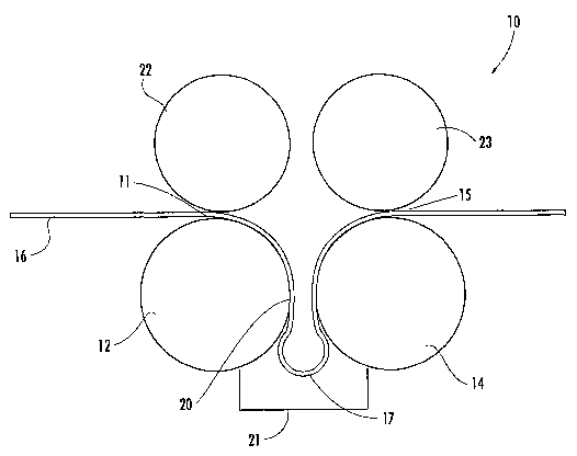
Figure 1 is a schematic side view of parts of the fabric dewatering device
showing a first embodiment which includes a top roll which forms a leading nip
and a trailing nip.
Figure 2 is a schematic side view of parts of the fabric dewatering device
showing a second embodiment which includes a top lead roll forming a lead nip
and a top trailing roll forming a trailing nip.
Figure 3 is a schematic side view of parts of the fabric dewatering device
showing a third embodiment which includes a rider roll inserted in a trough
portion
of the fabric.
Figure 4 is a schematic side view of parts of the fabric dewatering device as
shown in Figure 3 further comprising an air plenum positioned above the rider
roll.
Figure 5 is a schematic side view of parts of the fabric dewatering device
showing a fourth embodiment which includes a shower pipe suspended above a
rider roll.
DETAILED DESCRIPTION OF THE INVENTION
The present invention now will be described more fully hereinafter with
reference to the accompanying drawings, in which preferred embodiments of the
invention are shown. This invention may, however, be embodied in many
different
forms and should not be construed as limited to the embodiments.set forth
herein;
rather, these embodiments are provided so that this disclosure will be
thorough and
complete, and will fully convey the scope of the invention to those skilled in
the
art. Like numbers refer to like elements throughout.
-5-
CA 02426017 2003-04-14
WO 02/48453 PCT/SE01/02750
Figures 1 through 5 schematically depict several embodiments of a fabric
dewatering device 10 for fabrics used in a papermaking process. Figure 1 is a
schematic depiction of a first embodiment of the fabric dewatering device 10
showing a continuous fabric 16 passing through the device. The fabric passes
through a lead nip 11 formed between a top roll 13 and a leading guide roll
12.
The fabric then passes through a trailing nip 15 formed between the top roll
13 and
a trailing guide roll 14. Between the lead nip 11 and the trailing nip 15 the
fabric
16 forms a loop 20 with a trough portion 17 that has a small radius relative
to that
of the leading and trailing guide rolls 12 and 14. Movement of the fabric 16
with a
relatively high linear speed induces a centrifugal force that throws water out
from
the fabric when it is forced to swing through the relatively small radius of
the
fabric loop 20 and trough portion 17. This water is captured and prevented
from
falling on electrical parts, or the paper web being manufactured, by a
collection
pan 21. ,
The leading guide roll 12 and the trailing guide roll 14 are preferably two
parallel cylindrical rolls of equal diameter and with hard outer surfaces. The
rolls
12 and 14 are rotatable about their respective long axes and are supported in
a
suitable frame (not shown) of a papermaking machine wherever dewatering a
fabric belt or web is desired. The rolls 12 and 14 extend in a cross-machine
direction, transverse to the direction of travel of the continuous fabric 16,
and are
the same length, or longer, than the transverse width of the fabric.
The top roll 13 is a rotatable cylindrical roll and has a covering 18 of
rubber
or other deformable material on its outside surface. Unlike the leading and
trailing
guide rolls 12 and 14, the top roll 13 has an adjustable center axis 19.
Adjustments
in the position of the center axis 19 can be either manual or by way of an
automatic
control in response to an electrical or mechanical signal. Preferably, a non-
contact
sensor 30 detects the position of the trough portion 17 and sends a signal to
a
controller 31, which is connected to an actuator (not shown) operable to move
the
roll 13 toward and away from the guide rolls 12 and 14.
Adjusting the position of top roll 13 in relation to the guide rolls 12 and 14
varies the amount of indentation of the deformable cover 18 at the leading and
trailing nips 11 and 15, which regulates the length of loop 20 and hence the
radius
-6-
CA 02426017 2003-04-14
WO 02/48453 PCT/SE01/02750
of the trough portion 17. Preferably, the minimum indentation required to grip
the
fabric 16 is used at the lead nip 11, while a greater indentation is used at
the
trailing nip 15 so that the fabric speed entering the trailing nip is reduced.
Because
the length of the fabric 16 will increase as tension is applied, the surface
speed of
the fabric at the entrance of the trailing nip 15 will always be slower than
the
surface speed of the fabric at the entrance of the lead nip 11. The fabric 16
runs at
constant tension and speed outside of the fabric dewatering device 10, but
between
the nips 11 and 15, the loop 20 runs at nearly zero tension and a lower
surface
speed. The fabric speed differential between the leading and trailing nips 11
and
15 depends on the modulus of the fabric 16. A lower modulus results in more
fabric stretch at the trailing nip 15, and hence a greater speed differential
between
the nips.
In other embodiments, it is possible to construct the top roll 13 of a range
of materials. For instance, the top roll 13 could be constructed entirely of
deformable material rather than a deformable cover 18 on a hard roll. Various
deformable materials can be used. Rubber is a suitable material due to its
relatively low modulus of elasticity, high durability and excellent friction
characteristics.
Any of the three rolls 12, 13 and 14 can be driven by a conventional drive
system such as an electric motor operably attached to the axes of the rolls
through
a speed reducer. Figure 1 depicts a drive 32 coupled with the top roll 13.
Driving
the leading guide roll 12, the top roll 13, or both, maintains tension on the
fabric as
it travels through the lead nip 11 on the upstream end of the dewatering
device 10.
Driving the trailing guide roll 14, the top roll 13, or both, restrains the
downstream
flow of the fabric as it travels through the trailing nip 15. Driving any one
of the
rolls 12,13 and 14 will result in rotation of all three rolls due to the
contact forces
present in both of the nips 11 and 15.
The actual dewatering process is best illustrated by describing the path of
the fabric 16 as it travels into and through the fabric dewatering device 10.
Upstream of the fabric dewatering device 10, the fabric 16 supports a paper
web
during the manufacturing process. In some applications, the paper web may be a
textured tissue paper that is dried on a through-air-drier (TAD) fabric. These
CA 02426017 2003-04-14
WO 02/48453 PCT/SE01/02750
fabrics have a special textured structure and a definite thickness. After the
fabric
16 is separated from the paper web, it is cleaned of any fibers or other
contaminates that adhered to it during the papermaking process. It is cleaned
using
a conventional washing technique that typically involves spraying water onto
the
fabric. Before the fabric returns to pick up more of the paper web, the fabric
16 is
drawn at a fixed speed into the fabric dewatering device 10 by the tension in
the
lead nip 11.
Due to the decrease in the speed of travel of the fabric 16 between the lead
nip 11 and the trailing nip 15, little or no tension is present in the loop 20
of the
fabric 16. There is clearance between the two guide rolls 12 and 14 in the
machine
direction. This permits the fabric 16 to form loop 20 by extending downward
over
a portion of the circumference of the leading guide roll 12. The bending
stiffness
of the fabric 16 causes the formation of the trough portion 17 below the plane
formed by the axes of the guide rolls 12 and 14. The loop 20 is completed as
the
fabric 16 extends up a portion of the trailing guide roll 14 and into the
trailing nip
15.
Water is expelled from the soaked fabric 16 because the relatively high
linear speed swinging through a small radius trough portion 17 induces large
centrifugal forces. Preferably, the diameter of trough portion 17 will be in
the
range of 50 mm to 100 mm. At a fabric speed of 15 meters per second (m/s), the
water experiences a force of over 450 times gravity for the 100 mm diameter
trough portion 17. Halving the diameter of the trough portion 17 to 50 mm
increases this to 900 times gravity. Because of the orientation of the loop 20
suspended between the guide rolls, the water tends to be expelled generally
downward and laterally outward. As it is flung out of the fabric 16, the water
is
captured in the collecting pan 21 disposed below and surrounding the trough
portion I7, where it flows away through a drain (not shown).
After the traveling fabric 16 exits the dewatering device 10 through the
trailing nip 15, its water load has been reduced. Depending upon the tolerance
of
the papermaking process for the remaining water in the web 16, it can either
be
immediately returned to pick up more of the paper web, or it can be sent to
another
drying apparatus. Vacuum and forced air drying apparatuses are usually
expensive
_g_
CA 02426017 2003-04-14
WO 02/48453 PCT/SE01/02750
to operate when water loads are high. However, the water load is greatly
reduced
when the fabric 16 has been pretreated by the dewatering device 10, making a
serial use of drying apparatuses an effective strategy for dewatering fabric.
The
fabric can be passed sequentially through two or more dewatering devices 10,
if
desired.
A second embodiment of the fabric dewatering device is schematically
depicted in Figure 2. The second embodiment replaces the top roll 13 of the
first
embodiment with a top leading roll 22 and a top trailing roll 23. The top
leading
roll 22 and the leading guide roll 12 form the lead nip 11. The top trailing
roll 23
and the trailing guide roll 14 form the trailing nip 15. Of the two rolls
forming
each nip 11 and 15, one of them is driven by a drive assembly (not shown). The
top leading roll 22 and the top trailing roll 23 can be run at different
speeds so as to
allow the formation of the loop 20. A sensor system 31 as described in the
first
embodiment can be used for detecting the position of the trough portion I7 to
control the speed of the two top rolls 22 and 23. An advantage of the use of
two
top rolls over one is that it eliminates the need for the deformable cover 18
and
allows freer air access through the gap between the top lead and trailing
rolls 22
and 23.
A third embodiment (shown in Figure 3) eliminates the top rolls and
includes a rider roll 24 that is inserted within the trough portion 17 of the
fabric 16
to control the position and geometry of the trough portion. The diameter of
the
rider roll 24 is preferably between 50 rmn and 100 mm. The ends of the rider
roll
24 need not be supported, but some form of restraint of the rider roll 24 in
the
cross-machine direction is required. Preferably, the roll ends are shaped into
blunt
cones (not shown) which are arranged to rub against plastic strips (not
shown).
Alternatively, light arms and bearings can support the ends of the rider roll
24.
The fabric 16 and guide rolls 12 and 14 provide the restraint required to
prevent the
rider roll 24 from whirling. This allows operation at higher rotational speeds
of
about 6000 rpm for the 50 mm diameter rider roll. The rider roll 24 may also
be of
disk type or other segmented construction, with or without a fixed or
revolving
shaft.
-9-
CA 02426017 2003-04-14
WO 02/48453 PCT/SE01/02750
Increasing the dwell length and time that the fabric passes through the
small-radius path increases the dewatering effect of the centrifugal forces
for a
given level of centrifugal force. The dwell time can be increased by
increasing the
angle of wrap of the fabric about the rider roll 24. The wrap is preferably on
the
order of 290°, which corresponds to a dwell length of about 250 mm and
a dwell
time of 16 ms at fabric 16 travel speeds of 15 m/s for a rider roll 24
diameter of
100 mm. The centrifugal forces exerted in this case are on the order of 450
times
the force of gravity (g). Operation at the same fabric speed with a 50 mm
diameter
rider roll 24 would double the centrifugal forces from 450 g to 900 g, but
would
halve the dwell length and time to 125 mm and ~ ms. Wrap angles of 200°
to 300°
are suitable.
The third embodiment can also include a midfeather deflector 27, which is
a plate structure positioned between the leading guide roll 12 and the
trailing guide
roll 14. The plate structure of the deflector 27 prevents water flung from the
portion of the fabric upstream of the trough portion 17 from rewetting the
exiting
portion of the fabric web 16 downstream of the trough portion 17.
Figure 4 depicts a fourth embodiment, which is similar to the third
embodiment, except that the rider roll 24 is permeable and air is discharged
through the permeable rider roll 24 so as to pass through the fabric 16. Air
flow
can be generated using an air knife (not shown) or an air supply plenum 25
with
the air flow directed toward the permeable rider roll 24 and the trough
portion 17.
Air flow can also be generated using a vacuum source (not shown) attached to
the
collecting pan 21 that would draw air through the permeable rider roll 24 and
the
trough portion 17. Preferably, a vacuum seal 26 on the collecting pan 21 seals
against the guide rolls to prevent leakage of air between the guide rolls 12
and 14
and the collecting pan. Using the air knife and the vacuum source together is
also
a possibility if additional air flow is desired through the loop portion 20.
Figure 5 schematically depicts a fifth embodiment comprising a fabric
cleaning device 10' that includes the use of a flooded nip and/or scarfing
shower to
clean and dewater the fabric 16. The device 10' includes a permeable rider
roll 24
and a shower pipe 29. The rider roll 24 is of larger diameter than in the
previously
described embodiments to allow clearance for the shower pipe 29 which is
-10-
CA 02426017 2003-04-14
WO 02/48453 PCT/SE01/02750
positioned above the rider roll. Water from the shower pipe 29 floods a nip 33
between the lead guide roll 12 and the rider roll 24 so as to clean the fabric
16 as it
passes around the rider roll 24. One or more dewatering devices (of any of the
previously described embodiments) could be arranged in series with the
cleaning
device 10' to cleanse and/or dewater the fabric 16 continuously, thus forming
a
cleaning and dewatering system. The large centrifugal forces in the cleaning
device 10' can increase cleaning efficiency, and the device 10' can have a
more
compact arrangement than a conventional flooded nip device.
Many modifications and other embodiments of the invention will come to
mind to one skilled in the art to which this invention pertains having the
benefit of
the teachings presented in the foregoing descriptions and the associated
drawings.
Therefore, it is to be understood that the invention is not to be limited to
the
specific embodiments disclosed and that modifications and other embodiments
are
intended to be included within the scope of the appended claims. Although
specific
terms are employed herein, they are used in a generic and descriptive sense
only
and not for purposes of limitation.
-11-