Language selection

Search

Patent 2426020 Summary

Third-party information liability

Some of the information on this Web page has been provided by external sources. The Government of Canada is not responsible for the accuracy, reliability or currency of the information supplied by external sources. Users wishing to rely upon this information should consult directly with the source of the information. Content provided by external sources is not subject to official languages, privacy and accessibility requirements.

Claims and Abstract availability

Any discrepancies in the text and image of the Claims and Abstract are due to differing posting times. Text of the Claims and Abstract are posted:

  • At the time the application is open to public inspection;
  • At the time of issue of the patent (grant).
(12) Patent: (11) CA 2426020
(54) English Title: GUIDE TUBE WITH THREADED ENDS AND WAIST
(54) French Title: TUBE GUIDE A EXTREMITES FILETEES ET FUT CYLINDRIQUE
Status: Expired and beyond the Period of Reversal
Bibliographic Data
(51) International Patent Classification (IPC):
  • E21B 17/00 (2006.01)
  • E21B 17/042 (2006.01)
  • E21B 19/16 (2006.01)
(72) Inventors :
  • LARSSON, KENNETH (Sweden)
  • REUTER, GOSTA (Sweden)
(73) Owners :
  • SANDVIK INTELLECTUAL PROPERTY AB
(71) Applicants :
  • SANDVIK INTELLECTUAL PROPERTY AB (Sweden)
(74) Agent: GOWLING WLG (CANADA) LLP
(74) Associate agent:
(45) Issued: 2009-07-07
(86) PCT Filing Date: 2001-10-12
(87) Open to Public Inspection: 2002-05-10
Examination requested: 2005-10-26
Availability of licence: N/A
Dedicated to the Public: N/A
(25) Language of filing: English

Patent Cooperation Treaty (PCT): Yes
(86) PCT Filing Number: PCT/SE2001/002225
(87) International Publication Number: SE2001002225
(85) National Entry: 2003-04-16

(30) Application Priority Data:
Application No. Country/Territory Date
0003916-4 (Sweden) 2000-10-27

Abstracts

English Abstract


The present invention relates to a guide tube and a drill string suitable
for mechanical handling in a rig for percussive top hammer rock drilling. The
guide tube has an outer diameter (D) which is substantially constant along the
axial extension of the tube and comprises a female thread in a sleeve in a
first
end and a male thread at a second end as well as a flush channel extending
throughout the tube. The sleeve has an axial length (L1). The guide tube
comprises a cylindrical waist in the vicinity of the first end. The waist has
an
axial extension (L2) that is longer than the axial length (L1) of the recess.


French Abstract

La présente invention concerne un tube de guidage et un train de tiges adaptés aux manipulations mécaniquement dans un appareil de forage destiné au forage de roches. Le tube de guidage (10) présente un diamètre extérieur (D) sensiblement constant sur la longueur axiale du tube et il comprend un filetage femelle (16) formé dans un évidement (32) ménagé dans une première extrémité (11) et un filetage mâle (15) formé à une seconde extrémité (13) ainsi qu'un canal de rinçage traversant (19) permettant d'acheminer le milieu de rinçage jusqu'à un trépan de forage de roches pour forage par percussion au marteau-perforateur. L'évidement présente une longueur axiale (L1). Le tube de guidage (10) comprend une taille cylindrique (23) à proximité de la première extrémité (11). La taille (23) présente une extension axiale (L2) plus longue que la longueur axiale (L1) de l'évidement (32).

Claims

Note: Claims are shown in the official language in which they were submitted.

6
CLAIMS
1. A guide tube adapted for use in a percussive rock drill string, the
guide tube comprising:
a main portion;
a sleeve disposed at a first end of the main portion, the sleeve
including a recess having a female screw thread formed therein; and
a male thread portion disposed at a second end of the main
portion, a flush channel extending completely through the main portion
and the male thread portion and communicating with the recess, the
recess having a first length extending along a longitudinal axis of the
guide tube;
the main portion including a section of reduced cross-section
disposed adjacent the first end for defining a waist of narrower cross
section than a maximum cross section of the sleeve, the waist having a
second length extending along the axis which is longer than the length
of the recess and shorter than a third length of the rest of the main
portion,
wherein a wall thickness of the waist is no less than a maximum
wall thickness of the sleeve.
2. The guide tube according to claim 1 wherein the waist is bordered
at its axial ends by first and second shoulders, the first shoulder
disposed between the waist and the sleeve.
3. The guide tube according to claim 2 wherein the second length
being at least 50% greater than the first length.
4. The guide tube according to claim 2 wherein at least a radially
outer portion of the first shoulder extends substantially perpendicularly
to the axis of the guide tube.
5. The guide tube according to claim 2 wherein the second shoulder
is of concave shape defined by a radius.

7
6. The guide tube according to claim 5 wherein a radially inner
portion of the first shoulder is of concave shape defined by a radius
smaller than a radius of the second shoulder.
7. The guide tube according to claim 1 wherein an outer periphery of
the waist is cylindrical and has a first diameter; a remainder of the main
portion has a second diameter; the first diameter being in the range of
60-80% of the second diameter.
8. The guide tube according to claim 1 wherein the outer periphery
of the sleeve is of cylindrical shape; the main portion having, except
along the waist, an outer diameter in the range of 0.9 to 1.3 times the
diameter of the sleeve.
9. The guide tube according to claim 1 wherein the flush channel has
a cross section within the waist which is smaller than a cross section of
the flush channel in a remainder of the main portion.
10. The guide tube according to claim 1 wherein the flush channel
includes a first portion disposed within the waist, a second portion
disposed in a remainder of the main portion, and a third portion
disposed within the male thread portion; a diameter of the first portion
being larger than a diameter of the third portion.
11. A drill string for percussive rock drilling; comprising a drill bit, a
guide tube connected to the drill bit, an extension rod connected to the
guide tube, and a shank adapter connected to the extension rod; the
guide rod comprising:
a main portion;
a sleeve disposed at a first end of the main portion, the sleeve
forming a recess having a female screw thread formed therein; and
a male thread portion disposed at a second end of the main
portion and threadedly attached to the drill bit, a flush channel
extending completely through the main portion and the male thread

8
portion and communicating with the recess, the recess having a first
length extending along a longitudinal axis of the guide tube;
the main portion including a section of reduced cross-section
disposed adjacent the first end for defining a waist of narrower cross
section than a maximum cross section of the sleeve, the waist having a
second length extending along the axis and being longer than the length
of the recess and shorter than a third length of the rest of the main
portion,
wherein a wall thickness of the waist is no less than a maximum
wall thickness of the sleeve.
12. A method of unscrewing a threaded joint between a member and a
guide tube of a drill string, the guide tube comprising:
a main portion;
a sleeve disposed at a first end of the main portion, the sleeve
forming a recess having a female screw thread formed therein; and
a male thread portion disposed at a second end of the main
portion, a flush channel extending completely through the main portion
and the male thread portion and communicating with the recess, the
recess having a first length extending along a longitudinal axis of the
guide tube;
the main portion including a section of reduced cross-section
disposed adjacent the first end for defining a waist of narrower cross
section than a maximum cross section of the sleeve, the waist having a
length extending along the axis and is longer than the length of the
recess; the method comprising the steps of:
A) positioning the sleeve above clamping shoes of a rig, wherein
the clamping shoes engage the waist, and the sleeve rests upon the
clamping shoes;
B) applying percussion to the threaded joint to loosen the thread
connection; and
C) unscrewing the joint.

Description

Note: Descriptions are shown in the official language in which they were submitted.


CA 02426020 2008-04-18
WO 02/36925 PCT/SE01/02225
1
GUIDE TUBE WITH THREADED ENDS AND WAIST
Field of the Invention
The present invention relates to a drill string and a guide tube for
percussive drilling in loose rock.
Prior art
At drilling especially in open-pit mining the rock is frequently cracked
due to previous explosions, such as is shown in Fig. 1. Often the ground is
made smooth by means of metres and metres of rock masses 6 such that
the drilling machine 1 shall be able to travel at the drilling site. It is
difficult
to drill straightly in cracked rock, and therefor different solutions have
been suggested to improve the straightness of the hole to be drilled.
Therefore, a guide tube 2 is provided in direct connection with the drill bit
so as to guide the progress;Qf the drill bit and so as to increase the
,.~,.
flushing speed outside and above the drill bit. The guide tube is about 4 to
6 meters long and comprises a male thread facing towards the drill bit and
a female thread facing towards the machine. The tube has to be extended
at holes which are deeper than the length of the guide tube, preferably with
rods that have smaller diameters than the tube with the intention to more
simply allow passage of the drill dust. A modern machine for drilling
comprises a tong 3 (Fig. 2) for seizing by means of friction close to the
upper end of the tube 2 at extension or unscrewing. Frequently, the joint is
tightened hardly during drilling and therefor the joint must be loosened by
use of percussion and then be unscrewn. At said loosening by use of
percussion, which may continue several minutes, the tube will slide
relative to the shoes or clamping means 4 of the tong 3 in the position

CA 02426020 2003-04-16
WO 02/36925 PCT/SE01/02225
2
according to Fig. 6 and furthermore, heat is developed in the joint.
Consequently, the tube end is deformed and martensite is formed in the
threads.
Obiects of the invention
One object of the present invention is to provide a drill string and a
guide tube for mechanical handling wherein the above-captioned
drawbacks are counteracted.
Another object of the present invention is to provide a drill string and
a guide tube for mechanical handling to simplify unscrewing of the thread
joint in percussive rock tool equipment.
Still another object of the present invention is to provide a guide tube
for mechanical handling which improves the life span of thread joints in
percussive rock tool equipment.
These and other objects have been achieved by a guide tube and a
drill string for mechanical handling such as is defined in the appended
claims.
Brief description of the drawings
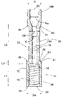
Fig. 1 schematically shaws a drilling machine for percussive top
hammer drilling, in a side view. Fig. 2 schematically shows a tong for
unscrewing of thread joints, in a top view. Fig. 3 shows a drill string
according to the present invention at an initial stage of the drilling. Fig. 4
shows the drill string according to the present invention at a later stage of
the drilling. Fig. 5A shows a guide tube according to the present invention
in a side view. Fig. 5B shows an end view of the guide tube in Fig. 5A. Fig.
5C shows a cross-section according to the line V-V of the guide tube in Fig.
5B. Fig. 6 shows a tong during gripping of an end of a prior art guide tube.
Fig. 7A shows the tong in seizing the end of a guide tube according to the
present invention. Fig. 7B shows the tong in gripping a guide tube
according to the present invention in position for unscrewing.

CA 02426020 2003-04-16
WO 02/36925 PCT/SE01/02225
3
Detailed description of the invention
An embodiment of a guide tube 10 according to the present invention
for mechanical handling in a rig for rock drilling is described hereinafter
with reference foremost to Figs. 5A-5C. The guide tube 10 consists of an
elongated body with a substantially cylindrical basic shape, with a
diameter D. The guide tube has a first end 11 with a sleeve or female
portion 12 and a second end 13 with a projecting spigot or male portion 14.
The spigot 14 has a substantially cylindrical external thread 15 and the
sleeve 12 has a substantially cylindrical internal female thread 16. The
female thread 16 or a recess 32 wherein the female thread is provided has
an axial length LI, which substantially extends from an end surface 24 of
the sleeve 12 to an abutment surface or bottom 18 in the sleeve.
A flushing channel which is generally depicted 19 extends internally
of the guide tube 10, through which a flush medium, usually air or water, is
transferred. The through-going flush channel 19 is provided to lead flush
medium to a rock drill bit 20 for percussive top hammer drilling. This
channel is suitably centrally positioned in the cylindrical body. The flush
channel comprises of at least three parts 19A, 19B and 19C. The axial
flushing channel 19 comprises an inlet 19A at the first end 11 and
terminates in an outlet 19C at;.the second end 13. The inlet 19A has a
diameter di that is greater than the outlet diameter do.
The guide tube 10 comprises a region of reduced diameter or a
cylindrical waist 23 in connection with or in the vicinity of the first the
end
12. The waist 23 has an axial extension L2 that is longer than said axial
length L1. A first shoulder 25 and a second shoulder 26 border the waist.
The first shoulder is provided in the vicinity of the female thread 16 at a
distance L3 from the bottom 18. The second shoulder 26 is provided at the
distance L2 from the first shoulder 25. The distance L2 is at least 50%
longer than the axial depth L1 of the recess 32, for example in one case L2
is 200 mm and L1 is 120 mm. The first shoulder 25 comprises a planar
portion 27, which is provided perpendicularly to the center axis CL of the
guide tube such to not force the shoes 4 apart, see below. The portion 27

CA 02426020 2003-04-16
WO 02/36925 PCT/SE01/02225
4
connects at 90 degrees to the jacket surface 28 of the sleeve. The jacket
surface 28 defines the diameter DA of the sleeve 12. The portion 27
connects radially inwardly via a transition 29 with a radius R1 to the
substantially cylindrical jacket surface 30 of the waist 23. The second
shoulder connects to the jacket surface 30 via a relatively large radius R2,
which is greater than the radius R1 of the first shoulder. The diameter D2 of
the waist is chosen in the interval 60-80% of the outer diameter D of the
guide tube. There exists a diametrical difference on each side of the waist
of -10% to +30%, such that the outer diameter D of the guide tube is 0.9*DA
to 1.3*DA, where DA is the outer diameter of the sleeve 12. The flush
channel 19 is restricted in the area 19A of the waist to retain the thickness
of the goods in the tube, i.e. to retain its capacity to transfer impacts and
the strength. The diameter D and the thickness of the goods are constant
at the mid portion of the tube. The guide tube 10 consists of the mid
portion 10A and the two ends 11 and 13 friction welded thereto. The mid
portion 10A has a channel 19B which has a diameter dm which is bigger
than, preferably at least twice the diameter d; of the inlet 19A. The parts
are
made of carbon steel but may possibly be chosen such that the ends 11
and 13 are made in stainless steel while the mid portion 10a is made in
carbon steel.
In Fig. 3 is shown the appearance of the drill string according to the
present invention carrying the guide tube 10 according to the present
invention at an initial stage of the drilling operation. The end 11 of the
guide tube 10 with the female thread is threaded firmly onto a conventional
shank adapter 22 and a conventional rock drill bit 20 having cemented
carbide buttons for percussive drilling is threaded firmly onto the other end
13 via the male thread. Thereby, drilling in metres and metres of rock
masses can be done with a maintained hole straightness and maintained
drill dust discharge since the travel of the drill bit is guided and the flush
speed is increased outside and above the drill bit due to the tube 10.
In Fig. 4 is shown the appearance of the drill string according to the
present invention with the guide tube 10 according to the present invention

CA 02426020 2003-04-16
WO 02/36925 PCT/SE01/02225
at a later stage of the drilling operation, i.e. when the drill bit 20 has
reached a depth of at least about 4 to 6 m. The threaded joint between the
shank adapter 22 and the guide tube 10 is thus unscrewn since the shoes 4
of the tongs 3 seize the sleeve 12, while the components are rotated
5 relative to each other. The shank adapter 22 is instead threaded into an
extension rod 21 when the guide tube 10 has been unscrewn. The usual
position of the shoes 4 at unscrewing or tightening of the extension rod 21
to the guide tube is shown in Fig. 7A, i.e. the shoes 4 clamps the sleeve 12.
If the threaded joint at unscrewing is stuck the position according to Fig.
7B is used, i.e. the shoes 4 clamp around the waist 23 while the shoulder
27 rests against upper sides 5 of the shoes. In this position the threaded
joint can be impacted loose without overheating the threads or deforming
the sleeve 12 since the support from the upper sides 5 is stable. The
diameter D2 of the waist 23 is chosen substantially as large as the diameter
of extension rod 21. The length L2 of the waist is chosen at least large
enough to allow positioning of the shoes 4 around the waist without any
problems.
Thus the present invention relates to a guide tube and a drill string for
mechanical handling in a rig for rock drilling which simplifies unscrewing
of thread joints at percussivp.;rock drilting equipment and which improves
the life-span for these thread joints.

Representative Drawing
A single figure which represents the drawing illustrating the invention.
Administrative Status

2024-08-01:As part of the Next Generation Patents (NGP) transition, the Canadian Patents Database (CPD) now contains a more detailed Event History, which replicates the Event Log of our new back-office solution.

Please note that "Inactive:" events refers to events no longer in use in our new back-office solution.

For a clearer understanding of the status of the application/patent presented on this page, the site Disclaimer , as well as the definitions for Patent , Event History , Maintenance Fee  and Payment History  should be consulted.

Event History

Description Date
Time Limit for Reversal Expired 2016-10-12
Letter Sent 2015-10-13
Grant by Issuance 2009-07-07
Inactive: Cover page published 2009-07-06
Inactive: Final fee received 2009-04-27
Pre-grant 2009-04-27
Notice of Allowance is Issued 2008-11-27
Letter Sent 2008-11-27
Notice of Allowance is Issued 2008-11-27
Inactive: Approved for allowance (AFA) 2008-10-29
Amendment Received - Voluntary Amendment 2008-04-18
Inactive: S.30(2) Rules - Examiner requisition 2008-02-12
Inactive: IPC from MCD 2006-03-12
Amendment Received - Voluntary Amendment 2005-11-30
Letter Sent 2005-11-08
Request for Examination Requirements Determined Compliant 2005-10-26
All Requirements for Examination Determined Compliant 2005-10-26
Request for Examination Received 2005-10-26
Letter Sent 2005-10-11
Letter Sent 2005-06-17
Inactive: Cover page published 2003-06-18
Inactive: Notice - National entry - No RFE 2003-06-16
Letter Sent 2003-06-16
Application Received - PCT 2003-05-20
National Entry Requirements Determined Compliant 2003-04-16
Application Published (Open to Public Inspection) 2002-05-10

Abandonment History

There is no abandonment history.

Maintenance Fee

The last payment was received on 2008-09-18

Note : If the full payment has not been received on or before the date indicated, a further fee may be required which may be one of the following

  • the reinstatement fee;
  • the late payment fee; or
  • additional fee to reverse deemed expiry.

Patent fees are adjusted on the 1st of January every year. The amounts above are the current amounts if received by December 31 of the current year.
Please refer to the CIPO Patent Fees web page to see all current fee amounts.

Owners on Record

Note: Records showing the ownership history in alphabetical order.

Current Owners on Record
SANDVIK INTELLECTUAL PROPERTY AB
Past Owners on Record
GOSTA REUTER
KENNETH LARSSON
Past Owners that do not appear in the "Owners on Record" listing will appear in other documentation within the application.
Documents

To view selected files, please enter reCAPTCHA code :


To view images, click a link in the Document Description column. To download the documents, select one or more checkboxes in the first column and then click the "Download Selected in PDF format (Zip Archive)" or the "Download Selected as Single PDF" button.

List of published and non-published patent-specific documents on the CPD .

If you have any difficulty accessing content, you can call the Client Service Centre at 1-866-997-1936 or send them an e-mail at CIPO Client Service Centre.


Document
Description 
Date
(yyyy-mm-dd) 
Number of pages   Size of Image (KB) 
Description 2003-04-15 5 248
Drawings 2003-04-15 6 119
Claims 2003-04-15 3 97
Abstract 2003-04-15 2 56
Representative drawing 2003-04-15 1 21
Description 2008-04-17 5 246
Abstract 2008-04-17 1 16
Claims 2008-04-17 3 122
Representative drawing 2009-06-08 1 12
Reminder of maintenance fee due 2003-06-15 1 106
Notice of National Entry 2003-06-15 1 189
Courtesy - Certificate of registration (related document(s)) 2003-06-15 1 105
Acknowledgement of Request for Examination 2005-11-07 1 176
Commissioner's Notice - Application Found Allowable 2008-11-26 1 163
Maintenance Fee Notice 2015-11-23 1 170
PCT 2003-04-15 6 256
Correspondence 2009-04-26 2 51