Note: Descriptions are shown in the official language in which they were submitted.
CA 02427458 2003-05-05
WO 02/49907 PCT/US01/44607
-1-
Description
METHOD AND APPARATUS FOR RETAINING A TRACK CHAIN JOINT
Technical Field
This invention relates generally to a track
chain for use on earthmoving machines, and more
particularly to a method and apparatus for retaining
the joints of the track chain.
Background Art
A track joint is usually held together by an
interference fit between the ends of the track pins
and their respective link bores into which the pin
ends are tightly received. Even though a very high
press force is used to press the links onto their
respective pin ends, the links still have a tendency
to move outwardly on the pin as axesult of working
forces exerted on the track during operation of the
machine. This outward movement causes the joints to
become loose or develop what is commonly referred to
as end play.
Various methods have been tried to limit the
amount of end play in track joints. Keeper assembles,
such as those disclosed in U.S. Patent No. 4,182,578
issued on 08 January 1980 and U.S. Patent No.
4,288,172 issued on 08 September 1981, both to Richard
Livesay et al. And both assigned to the assignee
hereof, have been successfully employed to reduce such
end play movement. In order to accommodate
CA 02427458 2003-05-05
WO 02/49907 PCT/US01/44607
-2-
manufacturing tolerances, joints utilizing such
keepers must have a certain amount of clearance which'
produces a limited amount of built-in end play. As a
result, these keepers reduce, but do not completely
eliminate end play.
Another method of limiting end play is
disclosed in U.S. Patent No. 3,831,257 issued on
27 August 1974, to Roger L. Boggs et al., which patent
is also assigned to the assignee hereof, wherein
welding about the ends of the track pin is used. In
this method, retention is dependent on the strength of
the weld. In practice, weld strength is difficult to
control with any degree of consistency. If a weld is
so weld that it breaks, all of its retention ability
is lost.
More recently, the method and apparatus for
retaining a track joint disclosed in U.S. Patent No.
5,201,171, issued on 13 April 1993, to Peter Anderton
et al. And also assigned to the assignee hereof, has
been successfully utilized. In such apparatus and
method, an appropriate groove must be machined in the
pin and material from the boss is displaced in the
radial direction into the groove of the pin.
The solution to the above problems is
hampered by another problem, which is inability to
change dimensions of the track: One such dimension is
the rail-to-rail width or gauge of the track. Like
railroad track, the track links provide a pair of rail
surfaces on which the wheels or rollers of the machine
ride. The rail width or gauge for any particular
CA 02427458 2003-05-05
WO 02/49907 PCT/US01/44607
-3-
machine is, for all practical purposes, permanently
set and cannot be changed. This is because any change
in rail gauge would require corresponding changes in
the remaining components of the machine undercarriage
and because the changed track would not be
interchangeable with the track of existing machines.
The present invention is directed to
overcoming the shortcomings of the prior attempts at
providing a track joint with restricted end play.
Disclosure of the Invention
In one aspect of the present invention,
there is provided a method of assembling a joint of an
endless track chain for track type machines to prevent
end play in the joint. The joint includes a pair of
links and a cylindrical pin. Each link includes a
laterally outwardly offset outboard end collar having
a boss extending outwardly therefrom and a bore
therethrough each boss having a side surface. The pin
includes opposite end portions, each end portion being
non-rotatably mounted into a respective one of the
bores of the outboard end collars. The method
comprising the steps of forming a annular groove about
each of the end portions of the pin, placing a swage
tool against the side surface of the boss in axial
alignment with the pin, applying a sufficient force on
the swage tool to form at least one mechanically
formed nodule protruding from the side surface of the
boss into respective one of the grooves of the pin,
CA 02427458 2006-11-28
68297-1030
-4-
the nodule having a cross-sectional configuration
substantially conforming to the groove.
I:n accordance with another aspect of the
present invention, an apparatus for retaining the
track joints of an endless track chain for a track-
type machine is provided to prevent end play in the
joints. Each joint includes a pair of links and a
cylindrical pin. Each link has an outboard end collar
with a pin boss extending outwardly therefrom and a
bore therethrough. The pin boss has a side surface.
Each pin has opposite end portions, each end portion
being pressed and non-rotatably mounted into a
respective one of the bores of the outboard end
collars. The apparatus comprising an annular groove
formed in each of the opposite end portions of the
pin. Each groove is disposed within the bore at a
location a:long the pin boss. At least one mechanically
formed nodule protrudes from the side surface of the
pin boss into respective ones of the pin grooves. Each
nodule has a cross-sectional configuration
substantially conforming to its groove and is formed
from material that has been permanently extruded from
the side surface of the pin boss into the groove.
CA 02427458 2006-11-28
68297-1030
4a
In accordance with still another aspect of the
present invention, there is provided a method of assembling
a joint of an endless track chain for track-type machines to
prevent end play in the joint, the joint includes a pair of
links and a cyl:Lndrical pin, each link includes a laterally
outwardly offset outboard end collar having a boss extending
outwardly therefrom and a bore therethrough, each boss
having a outer side surface, and the pin includes opposite
end portions, each end portion being non-rotatably mounted
into a respective one of the bores of the outboard end
collar, said method comprising the steps of: forming an
annular frustoconical groove about each of the end portions
of the pin; placing a swage tool against the outer side
surface of the boss in axial alignment with the pin;
applying a sufficient force in the axial direction on the
swage tool to form at least one mechanically formed nodule
protruding from the outer side surface of the boss into a
respective one of the frustoconical grooves of the pin, the
nodule having a cross-sectional configuration substantially
conforming to the frustoconical groove.
In accordance with yet another aspect of the
present invention, there is provided a method of assembling
a joint of an endless track chain for track-type machines to
prevent end play in the joint, the joint including a pair of
links and a cylindrical pin, each link including a laterally
outwardly offset outboard end collar having a boss extending
outwardly therefrom and a bore therethrough, each boss
having a outer side surface, and said pin including opposite
end portions, each end portion being pressed and non-
rotatably mounted into a respective one of said bores of
said outboard end collars, the method comprising the steps
of: forming an annular frustoconical groove about each of
the end portions of the pin; placing a swage tool against
CA 02427458 2006-11-28
68297-1030
4b
the outer side surface of the boss in axial alignment with
the pin; applyirig a sufficient force on the swage tool to
form at least one mechanically formed nodule extruded from
the side surface of the boss into a respective one of the
frustoconical grooves, the nodule having a cross-sectional
configuration substantially conforming to the frustoconical
groove.
In accordance with a further aspect of the present
invention, there is provided an apparatus for retaining the
track joints of an endless track chain for track-type
machines to prevent end play in such joints, each joint
including first and second pairs of links and a cylindrical
pin, each link of the first pair of links having an inboard
end collar with a first bore therethrough, and each link of
the second pair of links having an outboard end collar with
a pin boss extending outwardly therefrom and a second bore
therethrough, the boss having a outer side surface, and the
pin having opposite end portions, each end portion being
pressed and non-rotatably mounted into a respective one of
the second bores of the outboard end collars, the apparatus
comprising: an annular frustoconical groove formed in each
of the opposite end portions of the pin, each frustoconical
groove being disposed within the bore at a location along
the pin boss; and at least one mechanically formed nodule
protruding from the outer side surface of the boss into
respective ones of the pin frustoconical grooves, each
nodule having a cross-sectional configuration substantially
conforming to its frustoconical groove and being formed from
material that has been permanently extruded from the side
surface of the pin boss into the frustoconical groove.
In accordance with a further aspect of the present
invention, there is provided an apparatus for mechanically
connecting joints of an endless track chain for track-type
CA 02427458 2006-11-28
68297-1030
4c
machines to prevent end play in such joints, each joint
including a track link and a cylindrical pin, each link
having an inboard end collar with a first bore therethrough
and an outboard end collar with a pin boss extending
outwardly therefrom and a second bore therethrough, the boss
having an outer side surface, the pin having an end portion
being pressed and non-rotatably mounted into a respective
second bore of the outboard end collar, the apparatus
comprising: an annular frustoconical groove formed in the
end portion of the pin, each frustoconical groove being
disposed within the base at a location along the pin boss; a
swage tool having a plurality of spaced swage segments
contacting the outer side surface of the pin boss and being
moveable in the axial direction to extrude a nodule from the
side surface of the pin boss into the frustoconical groove,
the nodule having a cross-sectional configuration conforming
to the shape and cross-section of the frustoconical groove.
Brief Description of the Drawings
Fig. 1 is a plan view of a portion of an endless
track chain embodying the present invention;
Fig. 2 is a transverse cross-sectional view taken
along line 2-2 of Fig. 1 through a hinge joint;
CA 02427458 2003-05-05
WO 02/49907 PCT/US01/44607
-5-
Fig. 3 is an exploded view showing a track
link, a swage tool and a track pin of the present
invention;
Fig. 4 is a fragmentary cross-sectional view
of one of the joints shown in Fig. 2 and illustrating
structure for mechanically interlocking the pin to the
link;
Fig. 5 is a diagrammatic cross-sectional
view of one of the joints showing the unswaged
structure;
Fig. 6 is a diagrammatic cross-sectional
view of one of the joints showing the swaged
structure; and
Fig. 7 is an end view of a swaged joint
taken along line 7-7 of Fig. 6 with the swage tool
removed.
Best Mode for Carrying Out the Invention
Referring to the drawings, an endless track
chain embodying the present invention is generally
indicated at 10 in Fig. 1 for use on a track type
machine (not shown). The track chain 10 is constructed
from a plurality of link sets 12 which are
articulately coupled in a transverse relation of the
chain 10 by a plurality of hinge joints 14. Each link
set 12 includes a pair of laterally spaced,
longitudinally extending links, one being a right-hand
link and the other being a left-hand link. As such
links are mirror images of each other, both are
referred to herein by reference numeral 16. Each link
CA 02427458 2003-05-05
WO 02/49907 PCT/US01/44607
-6-
16 is provided with an inboard end collar, or boss, 18
and an opposite outboard end collar, or boss, 20. The
inboard end collar 18 is laterally offset inwardly
toward the center of the track chain 10, while the
outboard end collar 20 is laterally offset outwardly
therefrom. Link 16 further includes a longitudinally
disposed rail surface 22. The rail surface 22 has a
predetermined overall width "W" between an inner edge
24 and an outer edge 26. The rail surface 22 includes
a full width central portion 28, a generally one-half
width outboard portion 30 which extends along the
outer edge 26 over the outboard end collar 20 and a
generally one-half width inboard portion 32 which
extends along the inner edge 24 over the inboard end
collar 18. The distance between the inner edge 24 of
one link in the link set 12 to the inner edge 24 of
the other link defines a rail gauge width "G".
The inboard end collar 18 has a first bore
34 therethrough extending from an inner surface 36 of
the inboard end collar to an outer surface 38 thereof.
The inner surface 36 is offset inwardly from the inner
edge 24 of the rail surface 22. The outer surface 38
is offset outwardly relative to the inboard portion 32
of the rail surface 22 so as to be disposed in a
position substantially closer to the outer edge 26 of
the rail surface 22 than to the inner edge 24 thereof.
This offset positioning of the inner and outer
surfaces 36,38, respectively, provide the first bore
34 with a predetermined bore length "L1" that is
greater than one-half the width of the rail surface
CA 02427458 2003-05-05
WO 02/49907 PCT/US01/44607
-7-
22. Preferably, the outer surface 38 is positioned
within a range of from substantially greater than .50
times to less than 1.0 times the rail width "W" from
the inner rail edge 24.
The outer end collar 20 has a second bore 40
therethrough extending from an inner surface 42 to an
outer side surface 44 of the outer end collar 20. Each
second bore 40 has a counterbore 46 adjacent the inner
surface 42. Each counterbore 46 has a radial shoulder
48 at the bottom thereof that`is disposed outwardly
from the inner surface 42. It should be appreciated
that the offsetting relationship of the end collars
18,20 permits the outboard end collar 20 of one link
set to overlap the inboard end collar 18 of an
adjoining link set in the track chain. As shown in the
drawings, the outboard side surface 44 of the outboard
end collar 20 is provided on a pin boss 50. The outer
surface 44 is offset laterally a substantial distance
from the outer edge 26 of the rail surface 22 to
provide the second bore 40 with a predetermined bore
length "L2" that is at least as great as the overall
width "W" of the rail surface 22.
The joint 14 includes a cylindrical pin 52,
a rotatable tubular bushing 54 and a pair of hardened
sleeve bearings 56. The pin 52 has opposite end
portions 58, each of which is pressed and non-
rotatably mounted into a respective one of the second
bores 40 of the outboard end collars 20 of each link
16 in a link set 12.
CA 02427458 2003-05-05
WO 02/49907 PCT/US01/44607
-8-
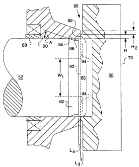
Referring more particularly to Figs. 3-6 the
joint 14 further includes a mechanical interlocking
structure 60 for locking the pin 52 to the outboard
end collar 20 to eliminate end play by preventing any
axial movement of the links 16 along the pin 52. The
mechanical interlocking structure 60 comprises a
circumferentially disposed groove 62 formed about each
of the ends 58 of the pin 52 and at least one
mechanically formed nodule 64, which is formed by
extruding the outer surface 44 of the pin boss 50 into
a respective one of the grooves 62. The groove 62 is
formed by a frustoconical surface 65 connected to a
radius 66. The frustoconiacl surface 65 is tapered
toward the pin 52 end and the radius 66 is located
outwardly of the frustoconical surface 65. The
frustoconical surface is tapered to have an angle "A"
of 15 degrees or less to provide a lead-in taper for
the pin 52 or it is pressed into the link. The
mechanically formed nodules 64 are preferably formed
by a swage tool 66 axially pushing on the outer
surface 44 of the boss 50. The pin 52 diameter
outwardly of the groove 62 defines a pin land 63 that
is reduced in size relative to the diameter inwardly
of the groove 62. The reduced pin land 63 diameter
provides clearance between the second link bore 40 to
prevent scoring of the second link bore 40 during
disassembly of the components. During disassembly the
pin 52 and the link 16 must be separated and the
reduced diameter will prevent scoring by the swaged
module.
CA 02427458 2003-05-05
WO 02/49907 PCT/US01/44607
-9-
The swage tool 67 includes a base 68
suitable to withstand high forces. The base 68 has a
first surface 70 and a second surface 72 having a
counterbore 73 for receiving the end 58 of the pin 52.
The counterbore of the swage tool 67 has an inside
diameter sized for receiving the load 63 of the pin
62. The diametrical clearance between the counterbore
73 and the pin land 63 is in the range of 0-3 mm. A
plurality of swage segments 74 extend from the second
surface 72 for contact with the outer surface 44 of
the boss 50. The swage segments 74 have a swage area
75 defined by a predetermined length L3, width W2, and
height H and the cross-section area of the groove 62
should be equal to or less than the swage area 75 of
the swage segments 74. The outer surface 44 of the
pin boss has a height of H2. In the present embodiment
four swage segments are shown however any number can
be used without departing from the scope of the
invention. The application of a sufficient force on
the swage tool 67 will result in the swage segments 74
extruding metal from the outer surface 44 of the boss
50 into the groove 62. The shape and cross-section of
the groove 62 is shaped and sized to control filling
of the groove 62 by the nodule 64 and also retention
between the pin 52 and the link 16.
The tubular bushing 54 is provided with a
pin bore 76, which is sized to freely rotatably mount
the bushing 54 about the pin 52. Bushing 54 has a pair
of opposite end faces 78 and is of a size to extend
CA 02427458 2003-05-05
WO 02/49907 PCT/US01/44607
-10-
between and be freely rotatable relative to the
inboard end collars 18.
The pair of hardened sleeve bearings 56 have
a inner face 80 and an outer face 82. The sleeve
bearings 56 are adapted to be press fitted in the
bores 34 of the inboard end collar 18. It should be
understood by those skilled in the art that such
sleeve bearings 56 must have a certain minimum length
that is sufficient to support the loads imposed upon
the joint 14 during operation, as dictated by the
weight and power of the machine on which the track
chain 10 is placed. As can be seen, the first bores 34
are substantially larger than the second bores 40 in
order to receive the sleeve bearings 56.
A first pair of seals 84 are provided for
sealing between the bushing 54 and the inboard end
collar 18 and a second pair of seals 86 provide
sealing between the inboard end collar 18 and the
outboard end collar 20.
A set of four thrust rings 88 is disposed
internally of each of the seals 84,86. The thrust
rings 88 are provided to maintain a predetermined
minimum axial spacing for the seals 84,86 to prevent
the seals from being crushed during assembly or
operation.
Referring to Figs. 5-7, each of the thrust
rings 88 includes a side surface 90, which interacts
with the link 16 to limit compression. The side
surface 90 has a predetermined surface area. Each of
the swage segments have an end surface 92 having a
CA 02427458 2003-05-05
WO 02/49907 PCT/US01/44607
-11-
predetermined surface area. The predetermined surface
areas are added together to determine the total
surface area of the swage segments. In order to
prevent imbedding of the thrust ring into the link the
total surface area of the segments relative to the
surface area of the ring must have a ratio of less
than 1Ø The end surface 92 of the swage segments 74
is perpendicular to the axial direction of the pin and
link boss and is flat.
The outboard end collar 20 of the link 16
extends axially outwardly to overlap the groove 62 a
predetermined length "L4". The minimum predetermined
length of overlap is about .5 mm and the maximum
length of overlap is about 3 mm. The predetermined
length of overlap must be maintained to fill the
groove 62 with the proper swaged module 64. If the
overlap is too small or large the groove will not be
filled by the swaging operation.
The height "H" of the swage segments 74 of
the swage tool 67 relative to the Height H2 of the
outer surface 44 of the pin boss 50 is equal to half
or less relative to the height of the outer surface.
The swage segments 74 contact only the inner half of
the outer surface 44 of the pin boss because the outer
half is needed to contain the swaged material module
to force the module into the pin groove 62. The swage
tool 67 having spaced segments 74 includes a surface
94 between the spaced segments 74. As the swage tool
is axially moved to swage the module 64 into the
groove 62 the surface 94 contacts the link boss
CA 02427458 2003-05-05
WO 02/49907 PCT/US01/44607
-12-
surface 44 to limit the penetration of the segments to
prevent excessive swaging as link material varies in
hardness from one link to another.
Referring to Fig. 7 the link boss surface 44
is shown as having a plurality of swaged pocket areas
96 each having a predetermined circumferential width
W2. All the circumferential widths are added together
to have a total circumferential width. The total
circumferential width should be less than 60% of the
circumference of the pin 52. This totaled
circumferential width is limited so that the track
joint can be rebuilt and reswaged or extruded at least
once.
Industrial Applicability
The endless track chain 10 constructed in
accordance with the teachings of the present of the
present invention provides a structure which maintain
structural integrity or load carrying capacity of the
track chain to eliminate reduce end play and maintain
the rail gauge dimension.
The mechanical interlocking structure 60 is
provided to eliminate endplay in the joint 14. The
interlock 60 includes the grooves 62 about the end
portions 58 of the pin 52. Once the track chain 10 is
assembled in a conventional manner with a track press,
a suitable swage tool 67 is placed on each of the
outer surfaces 44 provided on the bosses 50 of the
outboard end collars 20 and in axial alignment with
the pin 52. A suitable force is then applied to the
CA 02427458 2003-05-05
WO 02/49907 PCT/US01/44607
-13-
swage tool 67 by means of a press or the like to
extrude metal from the outer surface 44 of the pin
boss 50 into the grooves 62 about the pin 52. The
mechanically formed nodule 64 is formed by metal
protruding from the outer surface 44 of the pin boss
50 into the groove 62. The nodule 64 has a cross-
sectional configuration substantially conforming to
the shape ofthe groove 62. The groove 62 is formed by
a frustoconical 65 connected to a radius 66. In
operation, the nodule 64 prevents any axial movement
of the pin 52 in the second bore 40 in the outboard
end collar 20, thus ensuring that the joint 14 remains
tight without any end play.
To disassemble the track joint for repair, a
force is applied to spraed the links apart or push the
pin from the links. The applied force will shear the
module to allow for the pin to be removed. The pin
land is smaller in size than the rest of the pin to
provide clearance. This clearance will prevent
scoring of the bore of the pin boss.
In view of the forgoing, it is readily
apparent that the present invention provides a method
and apparatus for mechanically joining the track pin
to the track link to eliminate endplay in the track
chain to improve the joint in the track chain.
Other aspects, objects and advantages of
this invention can be obtained from a study of the
drawings, the disclosure and the appended claims.