Language selection

Search

Patent 2427586 Summary

Third-party information liability

Some of the information on this Web page has been provided by external sources. The Government of Canada is not responsible for the accuracy, reliability or currency of the information supplied by external sources. Users wishing to rely upon this information should consult directly with the source of the information. Content provided by external sources is not subject to official languages, privacy and accessibility requirements.

Claims and Abstract availability

Any discrepancies in the text and image of the Claims and Abstract are due to differing posting times. Text of the Claims and Abstract are posted:

  • At the time the application is open to public inspection;
  • At the time of issue of the patent (grant).
(12) Patent: (11) CA 2427586
(54) English Title: HOISTING HARNESS
(54) French Title: HARNAIS DE LEVAGE
Status: Term Expired - Post Grant Beyond Limit
Bibliographic Data
(51) International Patent Classification (IPC):
  • A61G 7/10 (2006.01)
(72) Inventors :
  • LILJEDAHL, GUNNAR (Sweden)
(73) Owners :
  • LIKO RESEARCH & DEVELOPMENT AB
(71) Applicants :
  • LIKO RESEARCH & DEVELOPMENT AB (Sweden)
(74) Agent: MARKS & CLERK
(74) Associate agent:
(45) Issued: 2009-09-08
(86) PCT Filing Date: 2001-09-19
(87) Open to Public Inspection: 2002-06-02
Examination requested: 2006-08-16
Availability of licence: N/A
Dedicated to the Public: N/A
(25) Language of filing: English

Patent Cooperation Treaty (PCT): Yes
(86) PCT Filing Number: PCT/SE2001/002006
(87) International Publication Number: WO 2002043641
(85) National Entry: 2003-04-30

(30) Application Priority Data:
Application No. Country/Territory Date
0004396-8 (Sweden) 2000-11-29

Abstracts

English Abstract


Hoisting harness for persons, where the lifting action takes place by a
harness consisting of a seat-piece (1) placed between the person's legs, to
which seat-piece a rear-piece (3) is connected, which runs against the
persons's back and further consists of a front piece (15) which runs against
the chest. The front-piece (15) and the rear-piece (3) in their free ends have
loops (8, 9, 17, 18) to be applied to a lift means, e.g. a lift hanger (19).
In order to avoid that the harness shall not be too tight across the chest
during the lifting action and that the harness is adaptable to the size of the
person's body, the front-piece (15) and the rear-piece (3) are connected by
two connecting bands (11, 12) each band passing one side of the body, whereby
the length of the connecting bands (11, 12) between the front-piece and the
rear-piece (3) is adjustable.


French Abstract

L'invention concerne un harnais de levage pour personnes, l'action de levage s'effectuant par un harnais qui comprend un élément siège (1) placé entre les jambes de la personne. Une élément arrière (3), rattaché à l'élément de siège s'étend contre le dos de la personne, comprend aussi une élément avant (15) s'étendant contre la poitrine de la personne. L'élément avant (15) et l'élément arrière (3) présentent, à leur extrémité libre, des boucles (8, 9, 17, 18) associées à un moyen de levage, par exemple un étrier de suspension (19). Pour éviter que le harnais ne serre trop la poitrine pendant l'opération de levage, et pour que le harnais s'adapte à la corpulence de la personne, l'élément avant (15) et l'élément arrière (3) sont reliés par deux bandes de liaison (11, 12) placées chacune sur un côté du corps et dont la longueur entre l'élément avant (15) et l'élément arrière (3) est réglable.

Claims

Note: Claims are shown in the official language in which they were submitted.

5
What is claimed is:
1. Hoisting harness for a person comprising:
a seat piece placed between the person's legs;
a rear piece connected to the seat piece, the rear piece
running against the person's back and upwards over the person's
shoulders;
a front piece connected to the seat piece, the front piece
running against the chest of the person and upwards over the
shoulders of the person,
the front piece and the rear piece, having free ends with
loops for engagement by a lift hanger; and
a connecting band protruding from each side of the rear
piece, each connecting band having a free end with several
loops;
whereby from each side of the front piece a lifting band
protrudes, and is insertable through one of the loops of the
connecting band so that the person in a comfortable way is
sitting on the seat piece, surrounded by the rear piece, the
front piece and the connecting bands.
2. Hoisting harness according to claim 1, wherein the rear
piece as well as the front piece each consists of two hoisting
bands, which are doubled from a point where a transverse band
connects the lifting bands.
3. Hoisting harness according to claim 1, wherein the
connecting bands are fastened to the rear piece so that the
connecting bands are at a small distance under the person's
armpits when the connecting bands connect the rear piece with
the front piece.

Description

Note: Descriptions are shown in the official language in which they were submitted.


CA 02427586 2008-04-11
1
HOISTING HARNESS
This invention relates generally to a hoisting harness for
persons, where the lifting action is taken place by a
hoisting harness comprising of a seat piece, which is placed
between the person's legs, to which seat piece a rear-piece
is connected, which runs on the person's back and upwards
over the shoulders and further consists of a front piece,
which runs against the person's breast and upwards over the
shoulders, whereby the front piece and the rear piece have
loops, or the corresponding, protruding from their free ends,
which loops will be applied to a lift means e.g. a lift
hanger.
Hoisting harnesses of this kind are very often so formed that
when a person is lifted sitting in the harness, pressure on
the chest or against the person's sides will be created and
this specifically goes for heavy persons having a corpulent
body. The problem is very obvious when lifting disabled
persons, old persons or weak persons, who can not use their
hands to keep off the tension forces of the hoisting harness.
An object of an aspect of the invention is thus to design a
hoisting harness, which is comfortable for the lifted person
during the lifting action and thereby will not be tight
across the chest or at least another point of the body and
which can be adapted to the size of the person's body.
Accordingly, in one aspect of the present invention there is
provided a hoisting harness for a person comprising: a seat
piece placed between the person's legs; a rear piece connected
to the seat piece, the rear piece running against the person's
back and upwards over the person's shoulders; a front piece
connected to the seat piece, the front piece running against the
chest of the person and upwards over the shoulders of the
person, the front piece and the rear piece, having free ends

CA 02427586 2008-04-11
la
with loops for engagement by a lift hanger; and a connecting
band protruding from each side of the rear piece, each
connecting band having a free end with several loops; whereby
from each side of the front piece a lifting band protrudes, and
is insertable through one of the loops of the connecting band so
that the person in a comfortable way is sitting on the seat
piece, surrounded by the rear piece, the front piece and the
connecting bands.
An embodiment of the invention will now be described with
reference to enclosed drawings.

CA 02427586 2003-04-30
WO 02/43641 PCT/SE01/02006
2
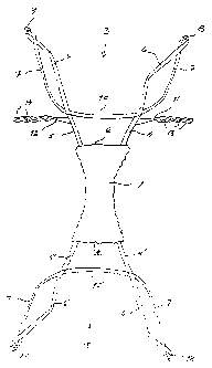
Fig. 1 is hereby a plan view of the harness.
Fig.2 is a harness according to the invention hanging from a
lift hanger without a person being lifted.
Fig. 3 is a view showing a person being lifted by the harness
according to the invention, the harness hanging from a lift
hanger.
Fig. 4 is the same as fig. 3 but the person being lifted is
seen from backwards.
Fig. 1 is thus a plan view of the harness. The harness in-
cludes a seat-piece 1 in the form of a piece of a cloth,, which
is placed between the person's legs. A rear-piece, generally
designated by 3 is fastened to the rear end 2 of the seat-
piece. This rear-piece 3 consists of two hoisting bands 4 and
5, which are prolonged by two parts 6 and 7, which in their
upper ends form a loop 8 and 9 respectively. The hoisting
bands 4 and 5 are transversally connected by a transverse band
10.
Two connecting bands 11 and 12 are connected with the hoisting
bands 4 and 5 at points approximately where the transverse
band 10 is connected to the hoisting bands 4 and 5. The two
connecting bands 11 and 12 are composed of several loops 13
and 14 respectively at their free ends.
The hoisting harness has also a front piece generally indi-
cated by 15. This front piece is connected to the front end 16
of the seat piece and is principally formed in the same way as
the rear piece, why it is not described more closely, and the
corresponding parts are indicated by the same numerals with

CA 02427586 2003-04-30
WO 02/43641 PCT/SE01/02006
3
prime as what is described concerning the rear piece. However,
as shown in fig. 1, the front-piece 15 has two lifting loops
and they are designated by 17 and 18.
In fig. 2 the harness is shown hanging from a lifting hanger
19. In this form the harness is hanging in the loops 8, 9, 17
and 18. In order to give the harness a closed form the hoist-
ing bands 6' and 7' of the front piece 15 are inserted through
any of the loops 12 and 13 respectively of the connecting
bands 11 and 12 respectively. A closed harness is thus formed
around the person's body by the rear piece 3, the front piece
and the two connecting bands 11 and 12, see also fig. 3.
The seat-piece is also included in this closed form of the
harness.
From fig. 3 it can be seen that the connecting bands 11 and 12
are placed under the armpits and preferably at a certain dis-
tance from the armpits so that the connecting bands do not
press uncomfortably into the armpits. By that the connecting
bands 11 and 12 can be inserted in suitable loops 12 and 13,
it is possible to place the transverse bands 10 and 10' so far
from each other that they are not uncomfortably tightened
against the chest and the back when the lifting action takes
place. The lifting bands will be stretched during the lifting
operation, which can have an influence on the tension of the
transverse bands 10 and 10'. It should also be observed that
the main part of the person's weight will be carried by the
seat-piece 1. It is also possible to adapt the harness so that
the weight is divided between the seat-piece and the connect-
ing bands by that the latter carry in the armpits. Further, it
is also possible that the weight can be carried by the trans-
verse bands 10 and 10' respectively because of a friction bet-
ween them and the body.

CA 02427586 2003-04-30
WO 02/43641 PCT/SE01/02006
4
An embodiment has been described above but within the scope of
the claims other embodiments are possible. Thus, the front
piece and the rear piece have been described consisting of
bands but it is obvious that parts of the front piece and the
rear piece can be formed from pieces of cloths instead of
bands, at least as far as up to the transverse bands.

Representative Drawing
A single figure which represents the drawing illustrating the invention.
Administrative Status

2024-08-01:As part of the Next Generation Patents (NGP) transition, the Canadian Patents Database (CPD) now contains a more detailed Event History, which replicates the Event Log of our new back-office solution.

Please note that "Inactive:" events refers to events no longer in use in our new back-office solution.

For a clearer understanding of the status of the application/patent presented on this page, the site Disclaimer , as well as the definitions for Patent , Event History , Maintenance Fee  and Payment History  should be consulted.

Event History

Description Date
Inactive: Expired (new Act pat) 2021-09-20
Letter Sent 2021-03-22
Letter Sent 2020-09-21
Common Representative Appointed 2019-10-30
Grant by Issuance 2009-09-08
Inactive: Cover page published 2009-09-07
Pre-grant 2009-06-23
Inactive: Final fee received 2009-06-23
Notice of Allowance is Issued 2009-01-12
Letter Sent 2009-01-12
Notice of Allowance is Issued 2009-01-12
Inactive: Approved for allowance (AFA) 2008-10-09
Amendment Received - Voluntary Amendment 2008-04-11
Inactive: S.30(2) Rules - Examiner requisition 2007-10-12
Amendment Received - Voluntary Amendment 2007-09-25
Letter Sent 2006-09-01
Request for Examination Received 2006-08-16
Request for Examination Requirements Determined Compliant 2006-08-16
All Requirements for Examination Determined Compliant 2006-08-16
Inactive: Cover page published 2003-07-31
Inactive: Notice - National entry - No RFE 2003-07-25
Letter Sent 2003-07-23
Application Received - PCT 2003-06-03
National Entry Requirements Determined Compliant 2003-04-30
Application Published (Open to Public Inspection) 2002-06-02

Abandonment History

There is no abandonment history.

Maintenance Fee

The last payment was received on 2008-09-09

Note : If the full payment has not been received on or before the date indicated, a further fee may be required which may be one of the following

  • the reinstatement fee;
  • the late payment fee; or
  • additional fee to reverse deemed expiry.

Please refer to the CIPO Patent Fees web page to see all current fee amounts.

Owners on Record

Note: Records showing the ownership history in alphabetical order.

Current Owners on Record
LIKO RESEARCH & DEVELOPMENT AB
Past Owners on Record
GUNNAR LILJEDAHL
Past Owners that do not appear in the "Owners on Record" listing will appear in other documentation within the application.
Documents

To view selected files, please enter reCAPTCHA code :


To view images, click a link in the Document Description column. To download the documents, select one or more checkboxes in the first column and then click the "Download Selected in PDF format (Zip Archive)" or the "Download Selected as Single PDF" button.

List of published and non-published patent-specific documents on the CPD .

If you have any difficulty accessing content, you can call the Client Service Centre at 1-866-997-1936 or send them an e-mail at CIPO Client Service Centre.


Document
Description 
Date
(yyyy-mm-dd) 
Number of pages   Size of Image (KB) 
Abstract 2003-04-30 1 50
Drawings 2003-04-30 4 73
Description 2003-04-30 4 140
Claims 2003-04-30 1 45
Representative drawing 2003-04-30 1 14
Cover Page 2003-07-31 2 43
Description 2008-04-11 5 156
Claims 2008-04-11 1 32
Representative drawing 2009-08-12 1 7
Cover Page 2009-08-12 2 43
Notice of National Entry 2003-07-25 1 189
Courtesy - Certificate of registration (related document(s)) 2003-07-23 1 106
Reminder - Request for Examination 2006-05-23 1 116
Acknowledgement of Request for Examination 2006-09-01 1 177
Commissioner's Notice - Application Found Allowable 2009-01-12 1 163
Commissioner's Notice - Maintenance Fee for a Patent Not Paid 2020-11-09 1 545
Courtesy - Patent Term Deemed Expired 2021-04-19 1 539
PCT 2003-04-30 6 239
Fees 2004-08-24 1 51
Fees 2005-08-31 1 51
Fees 2007-09-13 1 57
Fees 2008-09-09 1 57
Correspondence 2009-06-23 1 65
Fees 2009-09-03 1 65