Note: Descriptions are shown in the official language in which they were submitted.
CA 02427591 2003-05-07
1
pev;ce fir cnnve~ng and guiding a lead-iy strip
of a web in a paper machine
The invention relates to a device and method for conveying and guiding a lead-
in
S strip of a web in a paper machine.
This application is a division of corresponding Canadian Patent Application
Serial
No. 2,311,381 filed September 28, 1999.
As known in prior art, when a paper machine is started or after a web break, a
tail
of the web is passed through the paper machine by cutting from the web a
narrow
lead-in strip, which is guided manually through the machine by using air jets
as
well as different guide plates and threading devices. Continuously increasing
running speeds of paper machines have caused increasing problems in threading
of the web and thus new types of arrangements have been needed in order to
accomplish threading of the web.
With respect to the prior art relating to the invention, reference is made to
US
Patent 3,355,349, which discloses a belt conveyor intended for transfer of a
lead-
in strip to a calender or to a reel-up, or a belt conveyor disposed before a
calender. This known belt conveyor comprises two reversing rolls and a closed
and air pervious belt loop disposed therebetween and having an upper run which
is subjected to a vacuum. Said vacuum is produced by means of a suction box
which is placed inside the belt loop and which creates a vacuum effect on the
upper run of the belt to keep the lead-in strip in contact with the conveyor
belt. A
drawback in said known device has been that the device which is based on a
suction box is rather complex and heavy in structure and it includes a large
number of wearing parts and takes much space. This known device lacks the
possibility of profiling in a longitudinal direction, and in terms of
servicing it is
not advantageous. In this arrangement known from prior art, there is a high
vacuum on the entire run with the result that there is created heavy friction,
and
thus large motors are required for conveying the conveyor belt and the web.
The
purpose of the present invention is to develop further the above-mentioned
conveyor device so that the above-noted drawbacks may be avoided.
CA 02427591 2003-05-07
2
With respect to the prior art relating to the invention, reference is also
made to FI
Patent 69145, which discloses a device for conveying and guiding a lead-in
strip
of a web in a paper machine. This prior-art device comprises a conveyor belt
arranged around two or more reversing rolls, which belt is pervious to air and
has
devices arranged within its loop for producing a vacuum effect on the run of
the
conveying belt on which the lead-in strip is conveyed, the lead-in strip being
caused to adhere to and held in contact with said run of the conveyor belt by
means of said vacuum effect. On said conveying run of the conveyor belt,
inside
its loop, there are provided air blow means which include guide plates
extending
substantially parallel to the plane of the conveyor belt and the conveying
run, in
connection with which plates a dynamic vacuum effect can be produced by means
of air blowings, said lead-in strip being caused to adhere to and kept in
contact
with said conveying run of the conveyor belt by means of said vacuum effect.
This known arrangement requires an external source of air and a rather large
amount of air. This know device suffers from the problem that the air blow
means
placed one after the other in the running direction of the belt produce a
wavelike
vacuum curve, which changes from a negative pressure into a positive pressure
just before the next air blow means. A problem in this kind of device is that
it
may cause the web to form bights at the areas with a positive pressure. The
purpose of the invention is to develop further this known conveyor device such
that the drawbacks described described above may be avoided.
The present invention is directed towards the provision of a device for
conveying
and guiding a lead-in strip of a web, which device does not take much space,
which is readily servicable, which does not require a large amount of air,
thereby
allowing the amount of air used for producing a vacuum effect to be minimized,
and which device can be regulated in a longitudinal direction.
In accordance with one aspect of the present invention, there is provided a
device
for conveying and guiding a lead-in strip in a paper machine, comprising: a
conveyor formed of an air permeable material, said conveyor having a run with
opposed faces on respective sides, said lead-in strip being conveyed on a
first face
on a first side of said run; and means for producing a longitudinal vacuum
effect
CA 02427591 2003-05-07
3
relative to said run of said conveyor to cause said lead-in strip to adhere to
said
conveyor, said means for producing said vacuum effect on said run of said
conveyor located on a second side of said run of said conveyor.
In accordance with another aspect the present invention there is provided A
method for conveying and guiding a lead-in strip over a run of a conveyor in a
paper machine, comprising the steps of: directing a lead-in strip over a first
face
on a first side of a run of a conveyor; and producing a longitudinal vacuum
effect across the run of the conveyor in the direction of movement of the run
of
the conveyor.
On the conveying run of the conveyor belt in accordance with invention, inside
the loop of said run, foil ribs are fitted whose head is in contact with or in
the
immediate vicinity of the conveyor belt or wire or equivalent, which foil ribs
cause a vacuum level to be produced on the outlet face. In connection with the
foil nibs, blow nozzles are provided for blowing in the direction of the foil
such
that a vacuum area is achieved over the distance between two foil heads. The
foil
head provides a vacuum area without an external source of air as the head
guides
air away from its outlet side.
In accordance with an advantageous embodiment of the invention, the conveyor
belt/band/wire is rotated by an electric motor by means of a cogged belt or by
a
compressed-air motor from the end of a roll. The advantages of the cogged belt
drive include non-slipping acceleration and deceleration, an even driving
speed
and easy controllability. Air blown through the compressed-air motor or
obtained
from a separate compressed-air source is passed into foil ribs which are
placed
under the conveyor belt and by means of which a vacuum can be produced under
the wire. The angle of the foil can be regulated, thereby allowing the vacuum
level of the foil to be regulated. If a desired vacuum level is not achieved
by the
action of the foil ribs only, it is possible to utilize the Coanda effect
which is
provided by means of compressed air or from residual air of the compressed-air
motor by blowing said air through a nozzle fitted in connection with the foil
rib
along the face of the foil rib. The blow nozzle may be divided into two or
more
sectors in the cross direction in order to regulate the cross direction blow
capacity.
CA 02427591 2003-05-07
3a
In accordance with one advantageous additional feature of the invention, the
foil
ribs are provided with curved guide faces which further guide the air flow
such
that the vacuum over the entire length between the foil ribs will remain as
desired,
and a harmful pressure pulse of positive pressure will not be generated.
CA 02427591 2003-05-07
WO OOI19013 PCT/F199/00795
4
The arrangement accomplished by means of a compressed-air motor in accordance
with the invention provides its vacuum by itself, and no external source of
air is
needed. Thus, the consumption of air can be minimized. Controllability is
provided
by regulating the angle of the foil or the amount of blown air. The distance
between
the foil ribs is chosen such that a desired vacuum effect can be maintained.
In accordance with one embodiment example, a high vacuum is used in the first
foil
nozzle, and when the conveyor belt is above the web, a vacuum is also needed
for
other nozzles. In certain applications, subsequent nozzles are not always
needed, for
example, in applications in which the transfer distance is not long and the
web is
situated above the conveyor belt. The vacuum level is regulated by regulating
the
foil angle or the pressure or the amount of the air blown from the foil and,
when
needed, a blowing can be provided at the end of the conveyor belt loop before
a
reversing roll for the purpose of separating the Lead-in strip from the
conveyor belt.
The friction surface in the arrangement in accordance with the invention is
almost
nonexistent, thereby allowing relatively small motors to be used. Owing to low
friction, the wear of the conveyor belt is also minimal, which increases the
service
life of the conveyor belt.
The arrangement in accordance with the invention may be accomplished such that
a
number of devices in accordance with the invention are placed one after the
other
forming a conveyor with a module construction for long draws.
The arrangement in accordance with the invention is of light construction and
easy
to service.
The invention is suitable for several different places of application in a
paper
machine, for example, for a press section, a size press, a coater, for a
transfer from
a dryer section to a calender or for a transfer from a calender to a reel-up.
The
invention may also be used when the web is passed over open nips, for example,
when using the on-line arrangement marketed under the applicant's trademark
CA 02427591 2003-05-07
WO 00/190I3 PC1'/FI99/00795
OptiLoad, and for a transfer from a dryer section to a reel-up as well as in
on-
machine coating devices. As is clear from the examples listed above, the
device in
accordance with the invention is applicable to several different draws in open
gaps
of a paper machine.
5
The invention can be readily combined with various other threading devices,
threading plates and threading blowings, etc. known in themselves.
In an advantageous embodiment example of the device in accordance with
invention,
foil nozzles may also be arranged in the longitudinal direction of the device,
in
which connection a vacuum in the longitudinal direction can be produced.
In addition, the angle of the foil ribs in accordance with the invention with
respect
to the running direction of the web can be regulated from a cross direction to
a
IS longitudinal direction in order to achieve a desired effect and in order to
affect the
position of the lead-in strip on the conveyor wire in a lateral direction.
The nozzles used may be slit or hole nozzles.
In the following, the invention will be described in more detail with
reference to the
figures in the accompanying drawing, to the details of which the invention is
not by
any means intended to be narrowly confined.
Figure 1A is a schematic view of the basic principle of the device in
accordance with
the invention.
Figure 1B is a schematic view of a vacuum level achieved by means of the
arrange-
ment in accordance with the invention as compared with a vacuum level achieved
by
means of an arrangement known from prior art.
Figure ZA is a schematic side view of one embodiment example of the invention.
CA 02427591 2003-05-07
WO 00/19013 PCTIF199/00795
6
Figure 2B is a schematic view of the ,embodiment example shown in Fig. 2A as
viewed from above.
Figure 2C is a schematic view of the area A in Fig. 2A.
Figures 3A and 3B schematically show some advantageous additional features of
the
device in accordance with the invention.
Figure 4 schematically shows one additional application of the device in
accordance
with the invention.
Figure 5 schematically shows some examples of the use of the invention.
Figure 6 schematically shows some further examples of the use of the
invention.
Figure 7 schematically shows a third application of the invention.
Figure 8 schematically shows pressure as compared with nozzle pressure at
different
foil angles.
Figure 9 schematically shows pressure as compared with nozzle pressure at
different
speeds.
Figure 10 schematically shows pressure as compared with nozzle pressure when
using fabrics having different permeability.
Figure 11 shows pressure profiles across the foil with different permeability
values
of the conveying fabric.
Figure 12 shows pressure profiles with different values of the foil angle.
CA 02427591 2003-05-07
WO 00119013 PCT/FI99/00795
7
Fig. 1A schematically shows the basic principle of the device in accordance
with the
invention. Underneath a conveying run 20A of a conveyor belt, wire, band or
equivalent 20, foil heads 10 are placed whose apex is in contact with or very
close
to the bottom face of the conveyor belt 20, and a vacuum is provided on the
outlet
face of the foil head. The running direction of the belt 20 is denoted with
the arrow
S in the figure. It is also possible to connect a blow nozzle 11 to the foil
heads 10,
from which nozzle a blowing P is blown in order to further intensify the
effect of
vacuum, and thus by the joint action of the foil head and the blowing an air
flow F
is produced which enhances the vacuum on the outlet side of the foil head. For
the
purpose of further enhancing the vacuum effect and the air flow, a curved air-
flow
guide face 12 may be placed after the blow nozzle 11, which guide face further
enhances the vacuum effect and guides the air flow. In the figure, the whole
of the
foil head and the nozzle 11, i.e. a foil rib, is designated by the reference
numeral
15. The nozzles 11 may be either slit or hole nozzles.
Fig. 1B schematically shows the vacuum effect achieved by the foil riblnozzle
combination 15, the dashed line D denoting the point of the apex of the foil
head 10
on the conveyor belt 20, and the curve A illustrating the vacuum to be
achieved, and
the line B of dots and dashes showing the vacuum effect achieved by means of
arrangements known from prior art. The horizontal axis C represents the zero
level
of pressure.
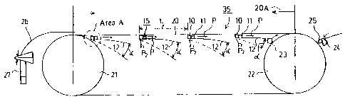
Figs. 2A and 2B show a device 35 in accordance with the invention comprising a
conveyor belt loop 20 which is arranged to be rotating around at least two
alignment
reversing rolls or equivalent 21,22 as an endless closed loop. The conveyor
belt 20
is permeable to air. Inside the conveyor belt loop 20, foil ribs 15 are placed
which
comprise a foil head 10 and a blow nozzle 11 to which a curved air-flow guide
face
12 is also advantageously connected. The conveyor belt 20 is preferably
rotated by
means of a compressed-air motor 30, and air blown through the compressed-air
motor is passed into the foil ribs 15 which are placed under the conveyor belt
20 and
by means of which a vacuum can be produced under the conveyor belt 20. The
angle
of the foil can be regulated, whereby the level of vacuum can be regulated. If
the
CA 02427591 2003-05-07
WO 00/19013 PCT/F199100795
8
necessary vacuum level is not achieved by regulating the angle, it is possible
to
utilize the Coanda effect which is provided from residual air of the
compressed-air
motor 30 or, when an electric motor is used, from a separate compressed air
source
by blowing air through the nozzle part 11 of the foil rib 15 along the face of
the foil.
Two blowings can be blown from the nozzle part 11 of the foil rib 15; one on
the
outlet side producing the Coanda effect, which blowing P preferably follows
the
curved guide face 12, and the other P2 on the inlet side in order to enhance
the air
flow F produced by the preceding foil rib 15.
A feed 31 and a flow-through 32 of compressed air as well as by-pass
regulating
valves 33 are also shown in Fig. 2B. As the figure shows, the compressed-air
motor
comprises ducts 34 to the foil ribs 15.
Fig. 2C schematically shows a partial enlargement of the area A in Fig. 2A
showing
a suitable shaping of the foil head 10 for the purpose of providing a desired
vacuum
as one advantageous embodiment example.
In the embodiment example shown in Fig. 2A, a lead-in strip is passed from the
preceding stage by means of a threading device 27, to which a guide plate 26
is
attached, onto the conveyor 35 of the lead-in strip in accordance with the
invention,
from the conveyor belt 20 of which conveyor the lead-in strip is separated by
a
blowing which is produced by a blow nozzle 23, and passed further by means of
a
blowing produced by a blow device 25 onto a guide plate 24 of the lead-in
strip.
The distance L between the foil ribs 15 used in the device 35 in accordance
with the
invention is 30 to 1000 mm, preferably 50 to 200 mm, the foil angle is below
10°,
preferably below 3°, and the air permeability of the conveyor belt 20
is below
10,000 m3/m2*h. The amounts of air used with a belt 20 of the width of 200 mm
are about 50 to 300 llmin, typically less than 400 l/min, i.e. about 2,000
l/minlwidth
metre, and pressures are used to pressures of up to about 2 bar. The
regulation angle
a of the foil is 1 to 10 ° , preferably I to 5 ° . The radius of
curvature of the guide
plates 12 is 300 to 1000 mm, preferably 400 to 600 mm.
CA 02427591 2003-05-07
WO 00119013 PCT/F199100795
9
In the embodiment example shown in Figs. 3A and 3B, a nozzle 17 extending in
the
longitudinal direction of the conveyor belt 20 is attached to the device 35 in
accord-
ance with the invention, from which nozzle bIowings P17 are blown, in which
connection a longitudinal vacuum effect is achieved which can be enhanced by
means of curved guide plates 18. As Fig. 3A shows, the foil ribs 15 can be
turned
from a cross direction to an oblique position and to a longitudinal position,
i.e. as
far as the running direction of the belt as desired in order to produce a
vacuum
effect of a desired type.
Fig. 4 'shows that blowings P2~ can be directed from the foil rib 15 such that
the
lead-in strip can be displaced in a lateral direction on the belt 20.
Figs. 5 to 7 schematically show some areas of application where the device 35
in
accordance with the invention may be used in conveyance and guidance of a Lead-
in
strip. The direction of running of the lead-in strip is designated by the
reference
numeral S and the same reference numerals are used of corresponding parts.
In Fig. 5, the Iead-in strip is passed from the last drying cylinder 51 of a
dryer
section 50 to a calender 60 first over a guide roll 52 to a device 351 in
accordance
with the invention. The device 351 of the invention placed in connection with
the
guide roll 52 can be turned such that the lead-in strip can be arranged either
to run
through all calendering nips N1-NN of the calender 60 ar such that the lead-in
strip
passes only through the lowermost nip NN of the calender 60. When the lead-in
strip
is passed such that calendering is performed in all the nips N1-NN, the Lead-
in strip
is passed by means of a second device 352 in accordance with the invention
onto a
guide roll 53, and therefrom further by means of a third device 353 in
accordance
with the invention into a first calendering nip N~ of the calender 60. After
that, the
lead-in strip of the paper web is passed to a reel-up after the last nip NN of
the
calender, first using a device 354 in accordance with the invention onto a
guide roll
61, therefrom via a device 355 in accordance with the invention onto the
following
guide roll 62 and further using a device 356 in accordance with the invention
via a
measurement device ?3 and a guide roll 74 to the reel-up 70 by means of two
CA 02427591 2003-05-07
WO 00/19013 PCT/FI99100795
devices 35~,35g of the invention placed. underneath. A movable air blow plate
77 is
placed after the measurement device 73 for conveying the lead-in strip, in
connection
with which plate a pneumatic cylinder 77a is provided for displacing the plate
77 in
the machine direction. As the figure shows, the devices 351 ... 35g in
accordance
5 with the invention can be placed above or under the lead-in strip and
provided with
movable air blow plates at scanners, through passages, etc.
Fig. 6 schematically shows an embodiment example in which a lead-in strip is
passed from the last drying cylinder 51 of a dryer section 50 directly through
10 measurement devices 81,73 to a reel-up 70. As Fig. 6 shows, devices 35 in
accord-
ante with the invention are placed in all suitable open draws over which the
Lead-in
strip is passed. The devices in accordance with the invention are numbered
consecu-
tively using a subscript 351 ... 356. Guide rolls are designated by the
reference
numerals 52,82,83,74.
Fig. 7 shows an embodiment example in which devices 351 in accordance with the
invention are used in a draw between a dryer section 70 and a measurement
frame
95. The lead-in strip is passed to a size press 90 and to an after-dryer
section 79 by
rope threading.
2O
Fig. 8 schematically shows pressures as compared with the nozzle pressure at
different foil angle values. The vertical axis shows the pressure in pascal
(Pa) and
the horizontal axis shows the nozzle pressure in bar (bar). The curve 101
represents
the situation when the foil angle is 0° +, the curve 102 represents the
situation when
the foil angle is 2°, and the curve 103 represents the situation when
the foil angle is
4°. The air permeability of the conveyor belt in this test was 8,000
m3/mZ/h and the
speed 1,800 mlmin. The curves 101,102,103 intersect the nozzle pressure at a
value
of about 0.22 bar, after which the highest vacuums were achieved at a foil
angle of
0°+. The expression 0°+ used above means that the angle is very
close to zero, yet
not negative.
CA 02427591 2003-05-07
WO 00/19013 PCT/F199I00795~
l1
Fig. 9 shows pressures as compared with the nozzle pressure at different
speeds
when the air permeability of the conveyor belt is 8,000 m3/m2/h and the foil
angle
2 ° . The vertical axis shows the pressure in Pascal (Pa) and the
horizontal axis shows
the nozzle pressure in bar (bar). The curve 104 represents the situation when
the
speed is 2,300 m/min, the curve 105 represents the situation when the speed is
2,000
mlmin, the curve 106 represents the situation when the speed is 1, 800 m/min,
the
curve 107 represents the situation when the speed is 1,500 m/min, and the
curve 108
represents the situation when the speed is 1,000 mlmin. As the curves of Fig.
9
show, increasing speed enhances the vacuum effect without the feed pressure of
air
being changed.
Fig. 10 shows pressures as compared with the nozzle pressure with different
air
permeability values of the conveyor belt, while the foil angle is 2°
and the speed
used is 1, 800 mlmin. The vertical axis shows the pressure in Pascal (Pa) and
the
horizontal axis shows the nozzle pressure in bars. The curve 109 represents
the
situation with an air permeability of the conveyor belt of 10,000 m31m2/h, the
curve
110 with an air permeability of 8,000 m3/m2lh, and the curve 111 with an air
permeability of 5,000 m3/mZ/h. In other words, by increasing the air
permeability
of the conveyor belt, the vacuum effect can be enhanced.
Fig. 11 shows pressure profiles across the foil with different air
permeability values
of the conveyor belt. The test was carried out while the speed was 1,800
mlmin, the
foil angle was 2°, and the nozzle pressure was 1 bar. The curve 112
represents the
situation with an air permeability value of 5,000 m31m2/h, the curve 113 with
an air
' permeability value of 8,000 m3/m2lh, and the curve 114 with an air
permeability
value of 10,400 m3/m2lh. The reference arrow 115 denotes the apex of the foil
and
the reference arrow l I6 denotes the rear edge of the foil. During the test,
the apex
of the foil was in contact with the lower face of the conveyor belt. The
vertical axis
shows the pressure in Pascal (Pa) and the horizontal axis shows the distance
from the
foil in millimetres (mrrt).
CA 02427591 2003-05-07
WO 00/19013 PCTIF199/00795
12
Fig. 12 shows pressure profiles at different foil angles. The curve I I7
represents the
situation when the foil angle is 4°, the curve 118 represents the
situation when the
foil angle is 2°, and the curve 119 represents the situation when the
foil angle is 0°.
The reference arrow 120 denotes the apex of the foil and the reference arrow
121
denotes the rear edge of the foil. The vertical axis shows the pressure in
pascal (Pa)
and the horizontal axis shows the distance from the foil in millimeues (mm).
It is seen from Figs. 11 and 12 that by means of the arrangement in accordance
with
the invention it is possible to create short machine-direction vacuum zones
which can
be regulated. The vacuum effect holding the belt is achieved immediately after
the
belt arrives at said vacuum zone.
Above, the invention has been described only with reference to some of its
advan-
tageous embodiment examples, to the details of which the invention is,
however, not
by any means intended to be narrowly confined. Many modifications and
variations
are feasible within the inventive idea defined in the following claims.