Note: Descriptions are shown in the official language in which they were submitted.
CA 02428377 2003-05-08
METHOD OF AND APPARATUS FOR MEASURING PLANARITY OF STRIP,
ESPECIALLY METAL STR IP
SPECIFICATION
S
FIELD OF THE INVENTION
Our present invention relates to a method of and to an
apparatus or device for measuring the planarity of strip,
especially metal strip, passing through a strip-rolling line or a
strip-processing line. More particularly, the invention relates
to the measurement of strip planarity in a system in which
tension forces acting on the strip are determined at least
sectionwise across the width of the strip and are evaluated.
BACKGROUND OF TFiE INVENTION
Metal strip after the strip-form:i.ng process, e.g.
rolling, may have defects with respect to planarity of the strip
which can be length. differences with respect to longitudinal
zones of the strip across the width thereof. The defects
generally are detectable as planarity defects and it is customary
_1-
CA 02428377 2003-05-08
to subject the strip to leveling depending upon the deviation of
the strip from true planarity. Indeed, deviation from planarity
may arise not only in strip-rolling lines but also in strip-
processing lines and the lack of planarity can be a function of
the deformation by rolling, of various leveling methods and
annealing or heat treatment generally of the strip.
Especially in the cold rolling of strip, it can be
observed that there is a certain tendency toward corrugation of
the strip which can arise because of differences in strip
thickness across the strip or longitudinally therealong and as a
consequence of the different degrees of plastic deformation which
can be carried out on the strip or can arise from the cold
rolling process. Apart from deviations in planarity there may be
distortion in the strip itself which are evident as strip camber
or edge waviness.
As a consequence, it has been customary to carry out
planarity measurements in metal strip traversing a strip-rolling
line or a processing line. For example, the tension force in the
strip can be determined and divided by the strip width and strip
thickness and utilized to provide a feedback signal which is used
to control strip tension. Corrugations in the strip have created
-2-
CA 02428377 2003-05-08
a
problems where the strip was to be used in some industries, for
example in the automobile sector, especially when the lack of
planarity of the strip exceeded certain limits. As a measure of
deviation from planarity, a so-called I-unit (IU) has been
developed. An IU corresponds to a tension. difference of 10-5
across a strip or across a longitudinal segment of the strip.
For example, when the tension differences across thve strip are
measured in length differences, for example ~1/1 is less than
10-5, the lack of planarity is deemed to be less than 1 IU. In
this relationship 01 is, of course, the difference in length as
measured cross the strip while 1 is tine length over which that
difference is applicable.
Any producer of strip must as a rule determine the
planarity limits of the product and thus planarity measurements
must be taken and these measurements utilized within the rolling
line or strip processing line to control the rolling or strip
processing line or to identify the quality of the strip produced.
Where such measurements are taken, they can be used in real time
to regulate a shaping or processing process, i.e. in parallel
therewith.
_3_
CA 02428377 2003-05-08
EP 1 116 952 A2 describes a contactless method of
measuring planarity while a system utilizing measurement rollers
in contact with a continually traveling strip to determine the
tension therein is described for example DE 199 18 699 A1.
While the contactless measurement process mainly
utilizes acoustic waves, ultrasonic waves or electromagnetic
measurements to detect the planarity, the roller approach
provides a magnetic measurement system and has the greatest use
in practice. The measurement roll approach of DE 199 18 699 A1
utilizes a multiplicity of measurement pickups which can be
received in recesses and spaced from the wall of the measurement
roller. The measurement roller can then be subdivided into so-
called disk segments which have been described for example in EP
1 182 424 A1. With the aid of the sensors, radial force
measurements are made where the strip is looped around a roller
and the output signals are measurements of the local tension
which can be divided by the width of the segment and the strip
thickness.
The planarity defects resulting from length differences
correspond to varying tensions at the respective segments since
the latter are measurements of the extent of elongation in the
-4-
CA 02428377 2003-05-08
metal strip and the effect thereof on the planarity. Reference
may be to the work "Formabweichungen in B~nderna Einteilung,
Entstehung, Messung and Beseitigung sowie quantitative
Bewertungsmethoden" (Shape Deviations in Stripe Classification,
Creation, Measurement and Evidence as well as Quantitative
Evaluation Methods by Gert M~cke, Kai F. Karhausen and Paul-
Dieter Putz (Stahl and Eisen 122 (2002) No. 2, Pages 33 ff).
The known mechanical measurement methods have some
basic drawbacks in that only a limited number of measurement
points are obtained over the strip width with local tension
measurement techniques. That means that a sufficiently precise
resolution requires a large number of sens~ars and hence a
comparatively costly measurement roller and thus significant
expense in evaluating the results. Furthermore, measurements at
edges of the strip are especially problematical because it is
there possible that a sensor will only paritially cover the strip
edge or be looged by the strip. The result can be errors.
Errors can also be produced when the position of the strip edge
is measured.
_5-
CA 02428377 2003-05-08
OBJECTS OF° THE INVENTION
It is the principal object of the present invention to
provide an improved method of measuring the planarity of strip
and especially metal strip passing through a strip-rolling line
for a processing line whereby one or more of the disadvantages or
drawbacks enumerated above can be obviated.
More specifically, it is an object of the invention to
grovide a planarity measuremer~t method for such strip which will
enable the tension distribution across the strip to be measured
with a high degree of precision, fine resolution and
comparatively inexpensively, so that errors in such measurements
in the region of the strip edges are avoided.
Another object is to provide a device which is
especially suitable for carrying out the method.
SUMMARY OF THE INVENTION
These objects are attained, in accordance with. the
invention in a method of measuring planarii~.y of strap passing
through a strip-rolling line or strip-processing 1i11e With the
steps of:
-6-
CA 02428377 2003-05-08
(a) measuring tension forces (FX) acting upon the strip
at least sectionwise over a width of the strip;
(b) summing the measured tension forces (FX) to form a
force-summation function (F(y)) across the strip width; and
(c) deriving a tension distribution function (dX(y))
from the force-summation function (F(y)).
A preferred device in accordance with the invention for
measuring such planarity includes:
an elongated sensor unit having at least one sensor for
measuring tension forces (Fx) acting upon the strip at least
sectionwise over a width of the strip, the sensor unit being
oriented at an inclination to a direction of travel of the strip;
and
a computer unit connected to the sensor unit for
summing the measured tension forces (Fx) to form a force-
summation function (F(y)) across the strip width and deriving a
tension distribution function (a~X(y)) from the force-summation
function (F (y) ) .
According to the invention, therefore, tension forces
are exclusively measured across the width of the strip and
optionally summed and the resulting summation force function over
CA 02428377 2003-05-08
the strip width is subjected to a differentiation to produce a
continuous tension distribution function. 2f desired, this
tension distribution function can be divided by the thickness of
the strip to obtain a specific tension distribution function
(QX(y)=dF(y)/dy/s in which the first term is the tension
distribution function and the second term is the first derivative
of the force summation function F(y) divided by the thickness s.
As a rule, the respective tension forces are added, although this
is not absolutely necessary. If the addition does not yield a
summation function, the summation function referred to can be a
summation force function defined only by the course of the
respective measured tension force across the width of the strip
from which the tension distribution function can be derived.
According to a feature of the invention, therefore, the
tension distribution function (o-X(y)) is derived from the force-
summation function (F(y)) as the first derivative (~x(y)=
dF(y)/dy)) thereof. The tension forces, or if one wishes
infinitesimal partial tension forces, are measured in the
individual longitudinal zones of the strip successively starting
from one strip edge or continuously across the strip width to the
other strip edge to integrate or sum that force. The detection
_g_
CA 02428377 2003-05-08
of the tension force can be contactless as by the use of sensors
which are acoustic, ultrasonic or electromagnetic, or via sensors
which come into contact with the strip, in every case providing
tension force outputs across the strip.
The sensor or sensors thus measure the tension forces
over the strip width with corresponding time offset and enable
the sumanation of the tension forces from strip edge to strip edge
and along a predetermined measurement line or across a
predetermined measurement surface to yield the force-summation
function.
During the planarity measurement between a starting
point and an ending point of the measurement or a starting region
and ending region of the sensor with respect to its cross
section, the measurement takes place over a measuring roller
within a certain measurement angle which itself is within the
looping angle of the strip and the measurement roller. Stated
otherwise, the starting and ending points or starting and ending
regions of the measurement line or of the sensor in projection on
the cross section of the measurement roll is within the looping
angle of the strip, e.g. the metal strip around the measurement
roller.
-9-
.. .. .. r .. ..._. m. . ....
CA 02428377 2003-05-08
The starting and ending points or starting and ending
regions of the measurement line or of the sensor in projection on
the cross section of the measurement roll is within the looping
angle of the strip, e.g. the metal strip around the measurement
S roller.
The measurement range over which the sensor or sensors
is or are effective for the edge to edge measurement, can be
subdivided into a plurality of partial measurements whose
individual measured tension farces can be combined to produce the
force summation function. The latter can be formed. in, for
example, a computer unit provided for this purpose.
It is thus possible to subdivide the strip width into
respective longitudinal zones in which respective partial tension
force measurements are made and from which respective force
summation functions are obtained or from which an overall force
summation function for each scan of the strip width by the sensor
set is generated.
According to a preferred feature of the invention, the
device comprises at least one measurement ~:oller around which the
strip is at least partially looped to form a looping angle (cc) of
-10-
CA 02428377 2003-05-08
the strip on the roller, the elongated sensor unit being a
measurement beam integrated in the roller.
The strip can be scanned with the measurement beam
between a starting position along one edge of the strip and an
S ending position along an opposite edge of the strip over a
measurement angle on the roller within the looping angle (ec).
In this case, a single sensor member is provided which
carries out a measurement over the full strip width for each
rotation of the measurement beam and, where a plurality of
measurement beams are provided in angularly spaced relationship,
a number of such scans from edge to edge can be provided with
each revolution of the measurement roller. where the sensor is
subdivided to provide axially offset sensors on the roller,
successive longitudinal zones of the strip are scanned. Where
the measurement beam in vertical projection lies at an angle of
inclination to the main axis of the measurement roller, a time
offset of the measurement from edge to edge is compensated by
having one portion of the sensor leading and another trailing in
the direction of rotation.
Since the sensor member progressively comes Within the
looping angle, for an exactly planar strip, there is a linear
-11-
CA 02428377 2003-05-08
i
increase in the tension force across the strip width. This is
not the case for a nonplanar strip.
The measured total force falls after reaching a plateau
or maximum (when the sensor in the form of a measurement beam
completely captures the tension force). The advancing band
rotation of the measurement roll then passes out of the looping
angle. Ideally there are rising and falling flanks with
different slopes.
The tension distribution function is therefore derived
by taking the derivative of the force summation function across
the strip width. This allows deviation of the force summation
function from linearity to be readily detected. When the
derivative of the force summation function across the strip width
is further divided by the strip thickness, one obtains a specific
tension force distribution of the strip as a function of the
strip width.
The measurement process of the invention can be carried
out in an ideal case with a single sensor and this need not have
the multiple sensors of the prior art and can be free from the
drawbacks described which arise because of sensors which measure
-12-
CA 02428377 2003-05-08
D
the tension force along the edges of the strip and thus at the
ends of the measurement range.
The precision of the measurement is then dependent upon
the resolution of the sensor. In the simplest case a force
measurement member, for example, a strain gauge or force
measuring cell (load cell) can respond to the force applied to
the measurement beam. Where desirable, two such force measuring
members can be provided in spaced relationship along the beam for
measuring the force applied thereto by the strip.
However, the resolution can be ix~creased by subdividing
the force measurement so that it is done with a plurality of such
beams which can be offset from one another across the strip width
so that each, individual measurement beam o;r partial beam can
measure the force applied by a respective longitudinal zone of
the strip. The partial beams each cover a respective partial
region of the measurement roll.
For example, if three partial measurement beams are
provided, the maximum force which is applied to each partial
measurement beam is one-third of the total force applied by the
strip to the measurement roll and representing the tension on
that strip as it is looped around the measurement roll. The
-13-
CA 02428377 2003-05-08
measurement precision can thereby be increased by a factor of
three.
The resolution of the force detection can also be
increased by making each measurement beam small and by inclining
the measurement beam so that the length of the measurement beam
can be greater than the width of the longitudinal zone of the
strip which the particular partial beam measures. A sliding mean
value is obtained from the partial beam and from th.e sliding mean
value the tension distribution function is derived again by
taking the first derivative of it.
The partial measurement beam integrated in the
measurement roll can have a low mass, especially when it is
comparatively small so that measurement errors resulting from
centrifugal force on the measurement beam as a result of rotation
of the measurement roll can be zero or negligible.
The method of the present invention and the apparatus
for practicing this method provide planarity measurement for
strips, especially metal strip, utilizing a simple structure
which gives the force summation function and the tension
distribution derived therefrom in a simple manner.
-14-
CA 02428377 2003-05-08
BRIEF DESCRIPTI~N OF THE 15RAVJING
The above and other objects, features, and advantages
will become more readily apparent from the following description,
reference being made to the accompanying drawing in which:
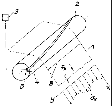
FIG. 7.a is a perspective view showing a system
according to the invention;
FIG. 1b is a cross sectional view through the
measurement roller and illustrating the measurement beams
angularly spaced therein;
FIG. 2 is a schematic elevational view, partly broken
away, of the device of FIG. 1a limited to the most important
components;
FIG. 3 is a diagram showing a metal strip at different
points during and prior to a measurement process;
FIG. 4 is a graph of the measurement described in
connection with FIG. 3 and representing the tension force FX
across the strip width B in terms of the distance y along the
strip width direction showing values at successive times t1, t2,
t3;
FIG. 5 is a graph of the force summation function F(y)
for a planar strip and for a corrugated strip;
-15-
CA 02428377 2003-05-08
FIG. 6 is a graph of the first derivative of the
tension force F/dy where F is the force summation function,
across the strip width y;
FIG. 7 is a graph of the tension. distribution function
o~x(y) as given by the graph of FIG. 6;
FIGS. 8 and 9 are diagrams showing other configurations
of the measurement roller;
FIG. 10a is a detail of a measurement roller with an
integrated measurement beam in vertical projection;
FIG. lOb is a side view of the measurement roller and
measurement beam of FIG. 10a;
FIG. 11 is a perspective view of the measurement roller
and the measurement beam of FIG. 10b; and
FIG. 12 is a side view of a measurement beam for
integration in a measurement roller and showing two force
measuring sensors in the form of strain gauges or load cells.
SPECIFIC DESCRIPTION'
A strip 1 which, according to the invention can be a
metal strip and is understood to be traveling continuously in a
strip processing line (e. g. a pickling, dressing, annealing,
-16-
CA 02428377 2003-05-08
tempering, descaling or coating line) or i.n a forming line such
as a rolling mill line, has its planarity measured across its
width B by passing the strip over a roller 2, hereinafter
referred to as a measurement roller, so that the strip is looped
partly around the roller, i.e. contacts th.e roller at an upstream
location and leaves the roller at a downstream location and
between the upstream and downstream locations a.s in contact with
the roller over a certain arc length which corresponds to a
looping angle.
The measurement roller 2 has a length at least equal to
the strip length B and is provided with at least one sensor, for
example, the sensor bar 4 which can extend over the length L of
the measurement roll, where L is greater than or equal to B.
FIG. 1a shows that the sensor bar 4 and the load cells
5 on which that bar bears, can extend at an inclination to the
axis of the roller 2 while FIG. 1 b shows that the looping angle
a extends over a fraction of the measurement roller 2. FIG. 1b
also indicates that a plurality of such measurement bars can be
provided at 4a, 4b and 4c in angularly equispaced relationship.
FIG. 2 shows the relationship between the length L and
the strip width B and by means of the arrow C indicates the
-17_
CA 02428377 2003-05-08
travel of the strip in the x direction. The dimensions of the
length L and the width B are in the y direction where x and y are
Cartesian coordinates in the plane of the strip 1. The system of
the invention responds to the tension force Fx on the strip and
the summation of the tension forces FX and the calculation of the
distribution function 6X are shown by a computer unit 3 shown in
FIG. 1a. The computer 3, of course, is connected to the sensor
4, 5 for the tension force FX.
The beam ~, which extends helically over a partial turn
in the measurement roller 2, is radially displaceable on that
roller and bears at its ends on two load cells or strain gauges 5
(see FIGS. la and 12) to produce the electrical signals which are
processed in the computer 3.
In spite of the measurement beam 4, an array of pins
can be provided which can be radially shiftable in respective
bores and which output electrical signals representing force
measurements by engagement with the strip as described in DE 199
18 699 A1 mentioned previously. Each of these pins can directly
bear on a force-measuring unit such as a load cell, outputting
its signal to the computer unit 3. Alternatively, the pins can
act upon an internal tube functioning as a measuring beam to
_ 18-
CA 02428377 2003-05-08
transmit pressure to a load cell ~ outputt:ing the force
measurement signal.
The measurement roller 2 in any of the embodiments
described enables a planarity of the strip 1 to be detected. It
is assumed that during the measurement, the tension applied to
the strip around the measurement roller 2 is sufficient so that
all of the infinitesimal strip zones across the width B are
practically rigid and thus that any corrugations or camber in the
strip have been stretched out. In that case, all of the length
differences 01 between the individual zones across the width of
the strip and represented by the vector arrows Z can be given in
terms of elongation differences in the strip travel direction x
as:
The result is a tension reference in the x direction as given by:
0~ =O.~.E~x
B~s
-19-
CA 02428377 2003-05-08
where E is the modulus of elasticity of tr.~e strip material, Fx is
the tension force in the x direction, B is the strip width and s,
the strip thickness.
From this latter relationship it is clear that changes
in the tension Ll6x can be derived from the measurement of the
tension force FX (when one divides the tension force FX by the
strip width B and the strip thickness s). This force Fx or
changes in this force OFX are determined with the measurement
roll 2. The corresponding tension force F.K in the strip travel
direction x need not be directly measured :but rather can be
obtained in terms of a radial component FrX resulting from the
looping of the strip 1 around the measurement roll 2 (compare
FIG. 1b) .
From FIGS. 2 and 3 it will be apparent that the sensor
4, 5 or the measurement roll 2 can be inclined with respect to
the strip travel direction x and in this manner by comparison to
the state of the art measurements in, for example, ~E 199 18 699
Al, the tension force FX is not detected sectionwise over the
strip width B or y, but rather is continuously obtained by what
amounts to a scanning across the width of the strip.
-20-
CA 02428377 2003-05-08
For this purpose the measurement: roll obtains tension
force FX at time-spaced intervals as has been shown diagrammatic-
ally in FIG. 3, initially at time t1, subsequently at time t2 and
then at time t3 at successive angular positions of the measure-
went roll 2 corresponding to the simultaneous travel of the strip
1 continuously around the measurement roll.
The time t~ represents the start:i.ng point and starting
region A of the measurement and the beginning of the contact
length K with which the beam ~ lies in measurement contact with
the strip. This contact length K is defined by a contact area 7
whose magnitude is given by the product K x B (compare FTG. 3)
corresponding to the area in which there is a contact between the
beam 4 and the strip 1. The looping angle a (compare FzG. 1b)
corresponds to the contact length K.
As soon as the starting point or starting region of the
measurement beam 4 reaches the edge 6 of tlae strip, the force
measuring cells 5 register a signal representing the radial
Component Frx of the tension force FX which is detected by the
measuring beam 4. As the strip 1 continues to travel in the
direction x and the strip rolls along the measuring roller 2, the
measuring beam 4 engages the strip in its inclined orientation
-21-
CA 02428377 2003-05-08
successively across the entire contact area or measurement area
represented by hatching at 7 in FIG. 3.
At the point t2, for example, the measurement is made
further into the contact area or region 7 and thus the force
measured by the load cell increases see FIG. 4). The force
measurement continues to the end point or end region E of the
measurement beam 5 at which the measurement beam is no longer in
contact with the strip.
As shown in FIG. 4, the measured tension force FX will
have a rising flank, a descending flank and a maximum in the form
of an plateau in which the measurement beam 4 lies fully within
the contact region 7.
When the strip is precisely planar, the tension force
FX detected by the measurement beam will linearly increase,
assuming that there are no elongation differences across the
width of the strip and the coefficient ~1/1 will have a zero
value. There is no ~Fx in the tension force Fx. When, however,
the strip is corrugated or possesses a degree of waviness or
camber resulting from differential elongation, this is recognized
as fluctuations in the tension force FX as measured and has been
shown in broken lines in FIG. 4 for the nonplanar strip.
-22-
CA 02428377 2003-05-08
This difference can also be seem in FIG. 5 in which the
tension force applied to the strip in newtons N as plotted
against the strip width coordinate y in mrn. Here the
measurements for a planar strip (points or circles) are compared
with the measurements for a corrugated strip (squares). The
ordinate represents the force summation function, i.e. F(y) - EFX
over the strip width at the particular strip width, coordinate y.
If one then takes the first derivative of the force
summation function F(y) with, respect to the strip width
coordinate y, i.e. forms the differential dF/dy, one obtains the
tension force distribution across the strip width as plotted in
FIG. 6.
FIG. 6 plots the differential dF/dy in N/mm versus the
strip width coordinate y in mm. The squares represent the
measurements for a strip having corrugations, i.e. differential
elongated parts while the circles or points represent the results
for a planar strip.
In the case of the specific differential coefficient,
i.e. the differential coefficient dF/dy divided by the strip
thickness s, one obtains directly a specific tension distribution
function, 6X(y) across the strip width and illustrated in FIG. 7
-23-
__ _. . .. . _ . ._ . _. __ _ . _~ _. . -. : _ , _ ... __.._. ._.___ __ . _ .
_
CA 02428377 2003-05-08
in which the tension distribution function is plotted along the
ordinate in megaPascal MPa versus the strip width coordinate y in
mm.
FIGS. 6 and 7 correspond to the measurement only along
a fraction of the total measurement represented by FIG. 4,
namely, the rising flank ahead of the plateau. A similar result
could be expected for the descending flank.
FIG. 8 shows that the measurement beam can be
subdivided into a plurality of partial measurement beams 4a, 4b,
4c which can correspond to three longitudinal measurement zones
along the strip and the number of such zones can be increased if
desired. Each of the measurement beams 4a, 4b, 4c then need only
take up one-third of the total tension force and as a result the
measurement precision or resolution can be significantly
increased.
FIG. 1b shows the only diagrammaltically further option
where the measurement roller has the three measurement beams
angularly spaced around the periphery of the measurement roller 2
and each beam is provided with a plurality of measurement cells 5
so that for each revolution of the roller z, there will be a
-24-
CA 02428377 2003-05-08
number of measurement zones as shown in FIG. 3. That too enables
an increase in the measurement precision.
FIG. 9 shows that the measurement beams 4 can be made
so small and inclined at such an angle that the starting or end
edge regions will occupy only a limited contact length K and
hence only a limited arc of the measurement roller 2 during the
starting and final stages of the measurement. Because the
contact region 8 of the starting or finishing edge engagement is
comparatively large and is detected only at the start and end of
the measurement, a sliding mean is obtained which eliminates
sharp signal contributions at the beginning and end of the strip
which may distort the results obtained.
We have faund that it is possible in this manraer to
provide a highly precise measurement of the tension distribution
function across the width of the strip without problematical
contributions at the edges which might otherwise result from a
precipitous drop in a measured value or partial tension
measurement at the starting and ending of the measurement. This
has been shown diagrammatically by the vectors for the tension
distribution in FIG. la.
-25-
CA 02428377 2003-05-08
The measurement roll 2 can be provided with a coating
of tungsten carbide or with a hard chromium layer to minimize the
wear and can have a cylindrical configuration although this is
not compulsory. The measurement roller 2 can also have a coolant
system or other temperature control arrangement for eliminating
the temperature effects on the planarity measurements. A
circulation of a coolant through. the measuring roller can also
eliminate temperature distortions at the force measurement cells
d. This is especially advantageous when the measuring device is
incorporated in a hot rolling line or the ;Like.
Within the framework of the invention is an embodiment,
previously mentioned and illustrated in FIG. 2 wherein pins
bearing on force sensors are provided to engage the strip instead
of the measuring beam 4. These pins have gaps between them and
are sealed relative to the surface of the measuring roller by
O-rings. plastic sensors or like sealing members which preclude
the penetration of dirt into any clearance around the pin.
The measurement roller 2 can have one or more
temperature sensors which not only enable t:he temperature of the
strip 1 to be determined and thus a temperature profile for the
strip to be measured but also enable control of the coolant
-26-
CA 02428377 2003-05-08
demand for the measuring roller 2, i.e. the flow of coalant which
will maintain a fixed temperature of the measuring roller and
thus reduce the temperature effects during measurement to a
minimum.
FIGS. 10a, lOb and 11 show that the measuring beam 4 in
vertical projection can have a predetermined angle of inclination
~3 to the longitudinal axis 9 of the measuring roller 2. The
measuring beam 4 lies generally along an ellipsoidal arc. As a
consequence, not only can the tension force FX and the tension
distribution function ~X(y) be obtained in the longitudinal
direction, i.e. the x direction but it is also possible to
measure as an alternative or an addition, tension forces in the y
direction.
FIG. 12 shows, as previously indicated, a measuring
beam 4 which is received within a corresponding recess in the
measuring roller and at its end can be provided with stems 5a
which bear on respective load cells 5 connected by electrical
conductors 5b to slip rings and wipers from which the measured
values are delivered to the computer. The slip rings for the
measuring roller have not been illustrated in the drawing.
- 2'~ -