Language selection

Search

Patent 2428670 Summary

Third-party information liability

Some of the information on this Web page has been provided by external sources. The Government of Canada is not responsible for the accuracy, reliability or currency of the information supplied by external sources. Users wishing to rely upon this information should consult directly with the source of the information. Content provided by external sources is not subject to official languages, privacy and accessibility requirements.

Claims and Abstract availability

Any discrepancies in the text and image of the Claims and Abstract are due to differing posting times. Text of the Claims and Abstract are posted:

  • At the time the application is open to public inspection;
  • At the time of issue of the patent (grant).
(12) Patent: (11) CA 2428670
(54) English Title: HIGHLY EFFICIENT HEAT EXCHANGER AND COMBUSTION CHAMBER ASSEMBLY FOR BOILERS AND HEATED AIR GENERATORS
(54) French Title: ECHANGEUR DE CHALEUR ET CHAMBRE DE COMBUSTION A HAUT RENDEMENT POUR CHAUDIERES ET GENERATEURS D'AIR CHAUD
Status: Deemed expired
Bibliographic Data
(51) International Patent Classification (IPC):
  • F28F 13/08 (2006.01)
  • F24H 3/08 (2006.01)
  • F28F 1/08 (2006.01)
(72) Inventors :
  • RIGAMONTI, ANGELO (Italy)
(73) Owners :
  • APEN GROUP S.P.A. (Italy)
(71) Applicants :
  • APEN GROUP S.P.A. (Italy)
(74) Agent: FINLAYSON & SINGLEHURST
(74) Associate agent:
(45) Issued: 2008-07-29
(22) Filed Date: 2003-05-13
(41) Open to Public Inspection: 2004-06-10
Examination requested: 2004-09-09
Availability of licence: N/A
(25) Language of filing: English

Patent Cooperation Treaty (PCT): No

(30) Application Priority Data:
Application No. Country/Territory Date
MI2002U-000573 Italy 2002-12-10

Abstracts

English Abstract


The present invention relates to a heat exchanger and
condensation combustion chamber assembly, comprising a plurality
of tubes and including a front plate and a rear plate connected
to the combustion chamber with a drop pattern. Each of the heat
exchanger tubes comprises a variable area cross section, with a
flat portion at a middle region, to provide a larger thermal
exchange surface. The middle region is subjected to a crossed
cut molding process to provide a helical type of fume path,
suitable to enhance the efficiency of the assembly, owing to an
increased thermal exchange between the fumes and heated air
flows. The combustion having a cross section of drop shape
allows to properly solve the problem related to the very high
temperatures generated by recent cylindric gas burners having a
metal mesh surface generating great amounts of heat, which must
be disposed of in a thermal exchange process with the heated air
flow.


Claims

Note: Claims are shown in the official language in which they were submitted.


9


WHAT IS CLAIMED IS:


1. A heat exchanger (10) and combustion chamber (3) assembly,
specifically designed for burners and heated air generators, said
heat exchanger (10) comprising a plurality of tubes (5) each having
a flat middle portion and being connected to one another and to
said combustion chamber (3) by a front plate (6) and a rear plate
(2), each of said tubes having a cross section area decreasing from
said front plate (6) to said rear plate (2), for compensating for
the loss of the volumes and the temperature of the fumes and for
holding the fume rate substantially constant, characterized in that
at said front (6) and rear (2) plate said cross section being
substantially circular, said substantially circular cross section
(12) is followed by an oval portion having a decreasing elliptical
cross section (13) in turn followed by said flat middle portion
meeting with said rear portion (14) of substantially circular
configuration coupled to said rear plate (2), and in that said flat
middle portion has a cross deformed surface, made by a deforming
mechanical process, and that said combustion chamber (3) is
arranged between two sets of said tubes (5).


2. The heat exchanger and combustion chamber assembly, according
to claim 1, characterized in that said tubes (5) provide a
conveying element for conveying a thermal exchange secondary fluid.

3. The heat exchanger and combustion chamber assembly, according
to claim 1, characterized in that said tubes (5) are connected to
said front plate (6) and rear plate (2) by welding.


4. The heat exchanger and combustion chamber assembly, according
to claim 1, characterized in that said combustion chamber (3) has
a drop configuration.


-10-


5. A heat exchanger and combustion chamber assembly for burners
and heated air generators, comprising a plurality of tubes for
conveying combustion fumes therethrough, said tubes being connected
to one another and to said combustion chamber by a front plate and
a rear plate, wherein said tubes have, at said front plate, a front
welding portion having a circular cross section, said front welding
portion being followed by a narrowing elliptical cross section
portion followed by a flat cross section portion in turn followed
by a circular cross section end attachment portion to be welded to
said rear plate, and wherein said flat cross section portion has a
mechanically deformed cross surface, allowing to generate a fume
turbulating fume path, thereby increasing a thermal exchange
between hot fumes coming from said combustion chamber and heated
air.


6. The heat exchanger and combustion chamber assembly, according
to claim 1, said fume generating combustion chamber having a drop
configuration, wherein an offset burner is housed in an offset
position in said combustion chamber.


7. The heat exchanger and combustion chamber assembly, according
to claim 1, wherein said tubes are adapted to also convey a thermal
exchange secondary fluid.

Description

Note: Descriptions are shown in the official language in which they were submitted.


CA 02428670 2003-05-13
2
BACRGROtJND OF T8E INVENTION
The present invention relates to a heat
exchanger and a condensation combustion chamber
assemby for the passage of the fumes generated by
air/gas combustion, produced by a pre-mixed burners
coupled to the combustion chamber.
Such an assembly, as is known, has a very
high efficiency, of the order of 105 and generates,
as combustion products, in addition to the combustion
fumes, also water steam, which is conveyed to the
outside environment, through a dedicated conveying
duct.
In such an embodiment, it is necessary to
increase or enhance the thermal exchange between the
fumes and secondary air to be heated, while
preventing any generations of laminar flows with
thermal gradients inside the exchanging tube, which
would cause a decrease of the thermal exchange with
the secondary fluid.
A further problem is that of the high
heating of the combustion chamber, operating in
cooperation with premixed gas burners having a very
high unit power for flame surface.
The first problem, related to the increase

CA 02428670 2003-05-13
3
of the thermal exchange in the heat exchanger tubes,
has been solved by providing "turbulating" devices,
inside said heat exchanger tubes.
The above mentioned devices, made of
stainless steel and having a rectangular cross-
section blade configuration, deformed in the form of
a spiral helix, were designed for generating a
turbulent motion in the hot fume path, to prevent any
laminar effect from occurring, with a consequent
decreasing of the heat amount being exchanged.
SUI~1ARY OF THE INVENTION
Accordingly, the aim of the present
invention is to solve the above mentioned problems.
Within the scope of the above mentioned
aim, a main object of the present invention is to
provide such a heat exchanger, of the tube sheet and
combustion chamber type, allowing to fit high thermal
loads, with a comparatively small exchange size, and
allowing, moreover, to hold a turbulent motion of the
combustion fumes, without generating negative load
losses through the system.
According to one aspect of the present
invention, the above mentioned aim and objects, as
well as yet other objects, which will become more

CA 02428670 2003-05-13
4
apparent hereinafter, are achieved by a heat
exchanger and combustion chamber asembly,
specifically designed for burners and heated air
generators, characterized in that the heat exchanger
comprises a plurality of tubes connected to one
another and to said combustion chamber by a front
plate and a rear plate, each said tubes having a
cross section area decreasing from said front plate
to said rear plate, for compensating for the loss of
the volumes and the temperature of the fumes and for
holding the fume rate substantially constant.
BRIEF DESCRIPTION OF THE DRAWINGS
Further characteristics and advantages of
the present invention will become more apparent
hereinafter from the following detailed disclosure of
a preferred, though not exclusive, embodiment of the
invention, which is illustrated, by way of an
indicative, but not limitative, example, in the
accompanying drawings, where:
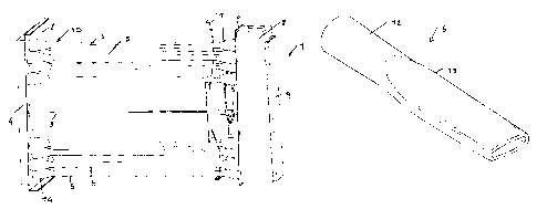
Figure 1 is a side perspective view of the
heat exchanger and combustion chamber assembly
according to the present invention;
Figure 2 is a side view of that same heat
exchanger and combustion chamber assembly;

CA 02428670 2003-05-13
Figure 3 is a top plan view of the heat
exchanger assembly and combustion chamber according
to the present invention;
Figure 4 is a perspective view of a length
of a heat exchanger tube; and
Figure 5 is a front elevation view of the
heat exchanger and combustion chamber assembly
according to the invention.
DESCRIPTION OF T8E PREFERRED EMBODIMENTS
With reference to the number references of
the above mentioned figures, the assembly according
to the present invention, which has been generally
indicated by the reference number 1, comprises a
combustion chamber 3, associated with a heat
exchanger, generally indicated by the reference
number 10, which essentially comprises a plurality of
heat exchanger tubes 5, the ends of which are coupled
to a rear tube plate or sheet 2 and a front tube
plate or sheet 6.
The rear tube plate 2, in particular, is
coupled to a rear manifold 4.
According to a main feature of the present
invention, each tube 5 has, starting from the front
plate 6 to the rear plate 2, a gradually tapering or

CA 02428670 2003-05-13
6
reducing cross-section.
More specifically, the tubes 5 have a front
attachment portion 12 (figure 4) having a circular
cross-section and comprising a portion or length 13
where the cross-section is narrowed to an elliptical
configuration.
On this section a deforming operation is
carried out, which can be defined as a cross
deforming operation, allowing to generate a tubular
type of fume path, thereby greatly increasing the
thermal exchange between the hot fumes coming from
the combustion chamber and heated air.
The heat exchanger tube 5, at the end
region 14 thereof, returns to a circular
configuration, thereby facilitating the coupling to
the plate, for example by a welding operation.
The shape or configuration of said tubes is
variable, depending on the requirements, and the
exchanger tube cross section must be so designed as
to compensate for the volume loss and fume
temperature, so as to practically hold a constant
fume rate, thereby providing an inner "turbulating"
motion, effective to improve the efficiency of the
assembly.

CA 02428670 2003-05-13
7
In particular the flattening-out of the
tube sheet assembly allows, in addition to providing
the above disclosed advantages, to properly hold the
fluid rates, and provide a secondary conveying
element, thereby enhancing the thermal exchange
properties.
A main feature of the combustion chamber 3,
is that the cross-section thereof has a drop
configuration, as clearly shown in figure 5.
This technical approach, would allow to use
a high power cylindric burner, while providing a
laminar motion of the cooling air on the exchanger,
in turn allowing to provide an even cooling, and
consequently a long duration of the heat exchanger.
It has been found that the invention fully
achieves the intended aim and objects.
In fact, the invention has provided a tube
sheet heat exchanger having a combustion chamber
which can be fitted to high thermal load, with a
comparatively reduced exchange size.
Moreover, the subject heat exchanger
provides the combustion fumes with a turbulent
motion, without generating undesired load losses
through the system.

CA 02428670 2003-05-13
g
Furthermore, the tube sheet allows to
design the exchanging tubes depending on the
exchanger power, thereby using_ the tube sheet as a
secondary fluid conveyor.
The heat exchanger and combustion chamber
provide a very reliable and safe operation, while
using commercially available elements, and with a
very low economic operation cost.
In particular, the heat exchanger according
to the invention allows to always maintain a great
turbulence of the combustion fumes, without any
important load losses, thereby properly solving the
thermal exchange problem.
The combustion chamber allows to use an
inner high power burner, thereby providing, owing to
the offset location of the burner and the chamber
drop configuration, a long duration of the exchanger
and combustion chamber itself.
In practicing the invention, the used
materials, as well as the contingent size and shapes,
can be any, depending on requirements and the status
of the art.

Representative Drawing
A single figure which represents the drawing illustrating the invention.
Administrative Status

For a clearer understanding of the status of the application/patent presented on this page, the site Disclaimer , as well as the definitions for Patent , Administrative Status , Maintenance Fee  and Payment History  should be consulted.

Administrative Status

Title Date
Forecasted Issue Date 2008-07-29
(22) Filed 2003-05-13
(41) Open to Public Inspection 2004-06-10
Examination Requested 2004-09-09
(45) Issued 2008-07-29
Deemed Expired 2010-05-13

Abandonment History

There is no abandonment history.

Payment History

Fee Type Anniversary Year Due Date Amount Paid Paid Date
Registration of a document - section 124 $100.00 2003-05-13
Application Fee $150.00 2003-05-13
Request for Examination $400.00 2004-09-09
Maintenance Fee - Application - New Act 2 2005-05-13 $50.00 2005-05-05
Maintenance Fee - Application - New Act 3 2006-05-15 $100.00 2006-05-11
Expired 2019 - Corrective payment/Section 78.6 $600.00 2007-01-19
Maintenance Fee - Application - New Act 4 2007-05-14 $100.00 2007-04-26
Final Fee $300.00 2008-04-02
Maintenance Fee - Application - New Act 5 2008-05-13 $200.00 2008-05-07
Owners on Record

Note: Records showing the ownership history in alphabetical order.

Current Owners on Record
APEN GROUP S.P.A.
Past Owners on Record
RIGAMONTI, ANGELO
Past Owners that do not appear in the "Owners on Record" listing will appear in other documentation within the application.
Documents

To view selected files, please enter reCAPTCHA code :


To view images, click a link in the Document Description column. To download the documents, select one or more checkboxes in the first column and then click the "Download Selected in PDF format (Zip Archive)" or the "Download Selected as Single PDF" button.

List of published and non-published patent-specific documents on the CPD .

If you have any difficulty accessing content, you can call the Client Service Centre at 1-866-997-1936 or send them an e-mail at CIPO Client Service Centre.


Document
Description 
Date
(yyyy-mm-dd) 
Number of pages   Size of Image (KB) 
Abstract 2003-05-13 1 30
Description 2003-05-13 7 208
Drawings 2003-05-13 4 98
Claims 2003-05-13 3 90
Representative Drawing 2003-09-08 1 16
Cover Page 2004-05-14 1 50
Claims 2007-04-04 2 74
Abstract 2007-04-04 1 27
Representative Drawing 2007-12-07 1 10
Cover Page 2008-07-17 1 47
Assignment 2003-05-13 4 126
Prosecution-Amendment 2004-09-09 1 32
Prosecution-Amendment 2007-04-04 8 277
Prosecution-Amendment 2006-10-11 3 94
Prosecution-Amendment 2007-01-19 2 49
Correspondence 2007-02-20 1 17
Correspondence 2008-04-02 1 35