Language selection

Search

Patent 2428675 Summary

Third-party information liability

Some of the information on this Web page has been provided by external sources. The Government of Canada is not responsible for the accuracy, reliability or currency of the information supplied by external sources. Users wishing to rely upon this information should consult directly with the source of the information. Content provided by external sources is not subject to official languages, privacy and accessibility requirements.

Claims and Abstract availability

Any discrepancies in the text and image of the Claims and Abstract are due to differing posting times. Text of the Claims and Abstract are posted:

  • At the time the application is open to public inspection;
  • At the time of issue of the patent (grant).
(12) Patent Application: (11) CA 2428675
(54) English Title: FORCED ENTRY RESISTANCE DEVICE FOR SASH WINDOW ASSEMBLY
(54) French Title: DISPOSITIF ANTI-EFFRACTION POUR FENETRE A GUILLOTINE
Status: Deemed Abandoned and Beyond the Period of Reinstatement - Pending Response to Notice of Disregarded Communication
Bibliographic Data
(51) International Patent Classification (IPC):
  • E05C 07/04 (2006.01)
  • E05B 15/02 (2006.01)
  • E05B 17/20 (2006.01)
  • E05C 03/04 (2006.01)
  • E05C 07/00 (2006.01)
  • E05D 11/00 (2006.01)
  • E05D 15/22 (2006.01)
(72) Inventors :
  • PETTIT, DEAN (United States of America)
(73) Owners :
  • NEWELL OPERATING COMPANY
(71) Applicants :
  • NEWELL OPERATING COMPANY (United States of America)
(74) Agent: GOWLING WLG (CANADA) LLP
(74) Associate agent:
(45) Issued:
(22) Filed Date: 2003-05-13
(41) Open to Public Inspection: 2004-11-06
Examination requested: 2003-05-13
Availability of licence: N/A
Dedicated to the Public: N/A
(25) Language of filing: English

Patent Cooperation Treaty (PCT): No

(30) Application Priority Data:
Application No. Country/Territory Date
10/430,803 (United States of America) 2003-05-06

Abstracts

English Abstract


A forced entry resistance device (20) is provided for a sash window assembly
(10). The
assemble has a keeper (28) mounted on a base (25) of an upper sash window (14)
and a locking
assembly (30) mounted on a top rail (27) of a lower sash window (16). The
locking assembly
(30) has a movable cam (36) fur engaging the keeper (28). The forced entry
resistance device
(20) comprises a member (20) adapted to be mounted to one of the base (25) and
top rail (27)
for preventing access to the cam (36).


Claims

Note: Claims are shown in the official language in which they were submitted.


6
Claims
What is claimed is:
1. A forced entry resistance device for a sash window assembly with a keeper
mounted
on a base and a locking assembly mounted on a top rail, the assembly having a
movable cam for
engaging the keeper, the forced entry resistance device comprising:
a member adapted to be mounted to one of the base and top rail for preventing
access to the cam.
2. The forced entry resistance device of claim 1 wherein the member comprises
a plate.
3.The forced entry resistance device of claim 2 wherein the plate has a lip
extending
generally away from plate.
4. The forced entry resistance device of claim 3 wherein the lip is integral
with the
plate.
5. The forced entry resistance device of claim 3 wherein the lip is generally
transverse
to the plate.
6. The forced entry resistance device of claim 3 wherein the lip extends
across a gap
formed between the base and the the top rail when the base and top rail are in
opposed relation to one
another.
7. The forced entry resistance device of claim 6 wherein the lip extends past
the gap.
8. The forced entry resistance device of claim 3 wherein the plate is mounted
to the
base and the lip extends past a plane generally defined by a vertical face of
the top rail.

7
9. The forced entry resistance device of claim 3 wherein the plate is mounted
to the top
rail and the lip extends past a plane generally defined by a vertical face of
the base.
10. The forced entry resistance device of claim 1 wherein the member is
integral with
one of the base or top rail.
11. The forced entry resistance device of claim 10 wherein the member
comprises a
protrusion adapted to extend past a dap formed by the base and the top rail
when the base and the
top rail are in opposed relation to one another.
12. The forced entry resistance device of claim 2 wherein the plate is
positioned within
a gap formed by the base and the top rail when the base and the top rail are
in opposed relation to
one another and wherein the plate has a thickness, at least a portion of which
is sufficient to
substantially fill the gap.
13. A sash window assembly comprising:
a master frame;
an upper sash window mounted within the master frame and having a base;
a lower sash window mounted within the master frame having a top rail;
a sash lock assembly comprising:
a keeper mounted on the base; and
a locking assembly mounted to the top rail, the locking assembly having a
movable
cam for engaging the keeper; and
means, mounted to one of the base and the top rail, for preventing access to
the cam;
wherein at least one of the upper sash window or lower sash window is slidable
within the master frame.
14. The sash window assembly of claim 13 wherein the means for preventing
access to
the cam comprises a plate.

8
15. The sash window assembly of claim l4 wherein the plate has a lip extending
generally away from the plate.
16. The sash window assembly of claim 15 wherein the lip is integral with the
plate.
17. The sash window assembly of claim 15 wherein the lip is generally
transverse to the
plate.
18. The sash window assembly of claim 15 wherein the lip extends across a gap
formed
between the base and the top rail when the base and the top rail are in
opposed relation to one
another.
19. The sash window assembly of claim 15 wherein the lip extends past the gap.
20. The sash window assembly of claim 15 wherein the plate is mounted to the
base and
the lip extends past a plane generally defined by a vertical face of the top
rail.
21. The sash window assembly of claim 15 wherein the plate is mounted to the
top rail
and the lip extends past a plane generally defined by a vertical face of the
base.
22. The sash window assembly of claim 13 wherein the means for preventing
access is
integral with one of the base or top rail.
23. The sash window assembly of claim 22 wherein the means for preventing
access
comprises a protrusion extending across a gap formed by the base and the top
rail, when the base
and top rail are in opposed relation to one another.
24. The sash window assembly of claim 14 wherein the plate is positioned
within a gap
formed by the base and the top rail when the base and the top rail are in
opposed relation to one
another, and wherein the plate has a thickness, at least a portion of which is
sufficient to
substantially fill the gap.

9
25. A sash window assembly comprising:
a master frame;
an upper sash window mounted within the master frame and having a base;
a lower sash window mounted within the master frame having a rail, a gap
defined
between the base and rail when the Base and rail are in opposed relation to
one another;
a sash lock assembly comprising:
a keeper mounted on the base; and
a locking assembly mounted to the top rail, the locking assembly having a
movable
cam for engaging the keeper; and
a plate mounted to the bast, the plate having a lip extending away from the
plate and
across the gap.

Description

Note: Descriptions are shown in the official language in which they were submitted.


CA 02428675 2003-05-13
I
H'OItC.'L'I) FM'1'RY RI~~SIS7'ANC',I~, 1)'!'~;VI(:I!; IaOIt 5~1~~L.I WLNDOW
ASSL'IdMIBLY
I~F?SC:RIf~fION
l,echnical Field
1'lais invention relates to a iorccd entry resistance device for slidable door
or window
assemblies. More particularly, it relates to a forced entry resistance plate
for a sash window
assembly.
I~ack~round of the Invention
Slidable door and window assemblies are commonly knowm in the art. The
assemblies
typically have a slidable member within a master frame. A double hung window
assembly
generally has an upper sash window and a lower sash window within a waster
frame. A sash lock
is cornlnonly provided to lock the window assembly. Typical sash locks draw
opposed frame
members ofthe sash windows together and lock the sashes preventing them from
sliding within the
1 ~ master frame.
One problem associated with typical double hung window assemblies and sash
locks, in
particular, is they can be manipulated by an intruder from outside the window
assembly. Sash
locks generally include some type of rotatable actuator ann and cam assembly.
The actuator is
rotatable between unlocked and locked positions to rotate the cam between
unlocked and locked
positions. With some sash locks, the actuator a:rm or cam may be manipulated
from the outside by
a skilled intruder using a thin knife, Miff wire, or other diabolical tool of
intrusion.
The present invention is provided to solve these and other problems.
Summary of the Invention
?5 The present invention provides a forced entry resistance device for
slidable door or window
assemblies.
~~.ccordingly, a forced entry resistance device is provided for a sash window
assembly. The
assembly has a keeper mounted on a base anti a locking assembly mounted on a
top rail. The
locking assembly has a movable cam for engaging the keeper. The forced entry
resistance device
;o comprises a member adapted to be mounted to one of the base and top rail
for preven~ing access
to the cam.

CA 02428675 2003-05-13
7
In ac-cordance with one aspect of the invention, the member comprises a plate.
.-according to another aspect of the invention, the plate has a lip extending
generally away
from the plate.
According to another arspect of the invention, the lip is integral with the
plate.
According to another aspect of the invention. the lip is generally transverse
to the plate.
According to smother aspect of the invention, the lip extends across a gap
formed between
the base and the top rail when the baise and top rail are in opposed relation
to one another.
According to another aspect of the invention, the lip extends past the gap.
According to another aspect of the invention, the plate is mounted to the base
and the lip
extends past a plane generally defined by a vertical face of the top rail.
According to another aspect o.Ethe invention the plate is mounted to the top
rail and the lip
extends past a plane generally defined by a vertical face of the base.
According to another aspect of the invention, the member is integral with one
of the base
or top rail.
According to another aspect of the invention, the member comprises a
protn.rsion adapted
to extend past a gap formed by the base and the top rail when the base and the
top rail are in
opposed relation to one another.
According to another aspect of the invention, the plate is positioned within a
gap formed
by the base and the top rail when the base and the top rail are in opposed
relation to one :mother and
wherein the plate has a thickness, at least a portion of which is sufficient
to substantially fill the
gap.
Other features and advantages of the invention will be apparent from the
following
specification including the following drawings.
Brief Description of the Drawings
FIG. 1 is a perspective view of a sash window assembly;
FIG. 2 is a cross sectional view of the sash window assembly, showing one
embodiment
of the present invention;
FIG. 3 is a perspective view of an embodiment of the present invention;
3o FIG. 4 is a perspective view of a locking assembly of a sash lock assembly;

CA 02428675 2003-05-13
(' (Ci. 5 is a cross sectional viwv e:~f a sash window asseruhly, similar to
FIG. 2, depicting an
additional embodiment of the present invention; and
1=IG. 6 is a cross sectit>nal view of a sash window assembly, similar to FIG.
2, depicting a
further embodiment of the present invention.
Detailed Description
While this invention is susceptible of embodiment in many different forms,
there is shown
in the drawings and will herein be described in detail preferred embodiments
of the invention with
the understanding that the present disclosure is to be considered as an
exemplification of the
to principles of the rovention and is ni>t intended to limit the broad aspect
of the invention to the
embodiments illustrated.
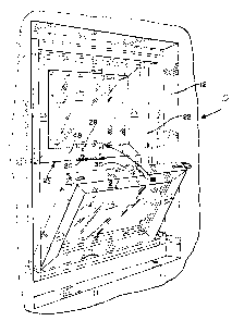
A sash window assembly 10 is illustrated in FIG.1. The sash window assembly 10
generally includes a master frame 1?, an upper sash window 14, a lower sash
window 16, a sash
lock assembly 18 and a forced entry resistance device 20. Other hardware may
also be included
such as tilt-latches and sash balance brake assemblies.
The upper sash window 14 and the lower sash window 16 are both mounted within
opposed
wide rails 22 on the master frame 12. The upper sash window 14 has a pair of
vertical stiles 23,
a top rail 24 and a base 2~. The lower sash window 16 has a pair of vezrtical
stiles 26, a top rail 27
and a base 29. In the embodiment shown, both the upper sash window 14 and the
lower sash
2o window 16 slide vertically within the master frame 12. However, it is
understood that only one of
the upper sash 14 or lower sash 16 may be slidable within the master frame 12.
when the upper sash window 14 is in its upper most position and the lower sash
window
16 is in its lower most position (FIGS. 2, 5 & 6), the base 25 of the upper
sash 14 and the top rail
2'7 of the Lower sash 16 are generally in opposed relation to one another. In
this position, the base
25 and the top rail 27 typically define a gap 46 (FIG. 2). It may be that the
gap 46 is negligible or
non-existent. However, even in this instance, there usually remains enough
play between the base
25 and the top rail 27 to allow a thin tool to be inserted between the base 25
and the top rail 27.
As further shown in FIGS. 1-2 and 4, the sash lock 18 generally comprises a
keeper 28 and
a locking assembly 30. The keeper 28 includes a keeper szzrfaee (not shown)
and a pair of mount
3o holes (not shown) for mounting the keeper 28 to the base 25.

CA 02428675 2003-05-13
4
Tlre locking assembly 30 is mounted to the top rail ?7 ,nnd is also shown in
FIG. 4. The
locking assembly 30 generally comprises a housing 32, an actuate~r arm 34, and
a cam 36. f1 shaft
(not Shown) connects the cam 3C~ to the actuator arm 34. 'The housing 3'?
includes a pair of mount
holes 3~ for mounting to the top rail 2!. ~l',he cam 36 is movable by rotation
of the actuator arm 34,
for engaging the keeper 2S. By engabement of the keeper 28 by the cam 36, the
sash lcck 1 S locks
the sashes 14, 16 together and prcvunts sliding movamerrt of the sashes 14, 16
relative to one
another. This prevents opening of the window assembly 10.
The forced entry resistance device or member?0, an embodiment ofwhich is shown
in FIG.
3, comprises a generally Ilat plate 4(> having a lip 42 extending from the
generally flat plate 40.
to The generally flat plate 40 is adapted for mounting to the bottom rail 25
of the upper sash window
14 and includes mount holes 44 for this purpose. In one preferred embodiment,
the mE:mber 20 is
mounted by screws. It is understood that other fasteners are possible
including adhesives or other
fasteners.
In the embodiment shown, the tW t plate 40 is mounted to an inner vertical
surf<zce or face
48 (FIG. 1 ) of the base 2~. Of course it is understood that the plate 40 may
be mounted in a recess
(not shown) of the base 2~. Vv'ith the upper sash window 14 in its upper most
position and the
lower sash window 16 in its lower must position, the lip 42 (FIGS. 2,5 & 6)
extends towards the
lower sash window 16 sufficiently far enough to obstnret or block access to
the small g ap 46 by a
thin diabolical tool of intrusion. This generally prevents access to the cam
36 by an intruder.
2o Additionally, the flat plate 40 has a length L sufficient to impede an
intruder's attempts at inserting
a thin diabolical tool of intrusion into the gap 46 from past an end 43 of the
plate 40 and
manipulating the cam 36.
Although the invention has been described as being applied to a vertically
sliding double
hung window, it is understood the invention can equally be applied to
horizontally sliding sash
2~ window arrangements or any operable sash that slides within a frame.
Additionally, it will be understood by those of ordinary skill in the art, the
forced entry
resistance device 20 may be integrally formed w°ith the base 25 while
remaining within the scope
of the invention, an embodiment of which is depicted in FIG. 6.
Additionally, it will be understood that the forced entry resistance device 20
may be
3o mounted to either the base 2~ or the top rail 27.

CA 02428675 2003-05-13
It is also understood tint the forced er~try~ resistance device 20 may take
other forms. For
example, the forced entry resistance. device 20 may comprise a generally flat
plate mounted on an
underside ~0 of the base 25 (FIG_ s), where n portion ohthe generally flat
plate extends ,past the
small gap 46. <'~lso, the forced entry resistranca device 20 my comprise a
protrusion 52 (FIG. 6)
s mounted to either the base 2 S or toh rail 27, where the protrusion 52
extends across the small gap
46. This protrusion ~2 may be integrally formed within either the base 25 or
top rail 27. In
addition, the forced entry resistance device 20 may comprise a generally flat
plate mounted to the
inside surface 48 of the base 25 where the thickness "T" of the generally flat
plate is sufficient to
substantially fill the small gap 46, thereby preventing access to the cam 36
via the gap 46. Of
1o course, in this case as with other c~rnbodiments, the forced entry
resistance device 20 may be
mounted to an outer surface or face 49 of the top rail 27.
Furthermore, it is understood that the member 52 or the lip 42 of the present
invention may
comprise a plurality of shapes and sizes which prevent access to the small gap
46 and therefore the
cam 36. These alternatives, as well as others, remain within the scope of this
invention.
t5 _Vloreover, it is understood that the forced entry resistance device 20 may
be formed from
any number of materials of sufficient strength to withstand the forces
involved in an attempted
manipulation by an intruder. For example, the forced entry resistance device
20 may be formed
from various commonly known metals ~uud alloys or hardened plastics possessing
the reduired
strength.
2o It can be appreciated that the forced entry resistance device 20 of the
present invention will
assist in preventing simple rotation of the cam 36. The torced entry
resistance device 20, while not
intruder-proof, will provide significant deterrence to forced entry and
uninvited manipulation of
the sash lock assembly 18 from outside the sash window assembly 10. It can
further be appreciated
that the forced entry resistance device 20 may be adapted for retrofitting to
existing sash window
25 assemblies 10 currently in use.
While the specific embodiments and various details thereof have been
illustrated and
described, numerous modifications come to mind without significantly departing
from the spirit
and the scope of protection limited by the following claims.

Representative Drawing
A single figure which represents the drawing illustrating the invention.
Administrative Status

2024-08-01:As part of the Next Generation Patents (NGP) transition, the Canadian Patents Database (CPD) now contains a more detailed Event History, which replicates the Event Log of our new back-office solution.

Please note that "Inactive:" events refers to events no longer in use in our new back-office solution.

For a clearer understanding of the status of the application/patent presented on this page, the site Disclaimer , as well as the definitions for Patent , Event History , Maintenance Fee  and Payment History  should be consulted.

Event History

Description Date
Inactive: Dead - Final fee not paid 2008-12-01
Application Not Reinstated by Deadline 2008-12-01
Inactive: Office letter 2008-10-21
Revocation of Agent Requirements Determined Compliant 2008-10-21
Appointment of Agent Requirements Determined Compliant 2008-10-21
Inactive: Office letter 2008-10-20
Deemed Abandoned - Conditions for Grant Determined Not Compliant 2007-11-29
Notice of Allowance is Issued 2007-05-29
Letter Sent 2007-05-29
Notice of Allowance is Issued 2007-05-29
Inactive: Approved for allowance (AFA) 2007-05-03
Amendment Received - Voluntary Amendment 2006-12-18
Inactive: S.30(2) Rules - Examiner requisition 2006-06-19
Amendment Received - Voluntary Amendment 2006-03-29
Inactive: IPC from MCD 2006-03-12
Inactive: S.30(2) Rules - Examiner requisition 2005-09-30
Letter Sent 2005-09-16
Application Published (Open to Public Inspection) 2004-11-06
Inactive: Cover page published 2004-11-05
Letter Sent 2004-03-10
Inactive: Inventor deleted 2004-03-09
Inactive: Office letter 2004-03-09
Inactive: Single transfer 2004-02-03
Request for Priority Received 2003-11-13
Inactive: First IPC assigned 2003-07-29
Inactive: IPC assigned 2003-07-29
Inactive: Courtesy letter - Evidence 2003-06-17
Inactive: Filing certificate - RFE (English) 2003-06-12
Application Received - Regular National 2003-06-12
Letter Sent 2003-06-12
All Requirements for Examination Determined Compliant 2003-05-13
Request for Examination Requirements Determined Compliant 2003-05-13

Abandonment History

Abandonment Date Reason Reinstatement Date
2007-11-29

Maintenance Fee

The last payment was received on 2008-04-24

Note : If the full payment has not been received on or before the date indicated, a further fee may be required which may be one of the following

  • the reinstatement fee;
  • the late payment fee; or
  • additional fee to reverse deemed expiry.

Patent fees are adjusted on the 1st of January every year. The amounts above are the current amounts if received by December 31 of the current year.
Please refer to the CIPO Patent Fees web page to see all current fee amounts.

Fee History

Fee Type Anniversary Year Due Date Paid Date
Application fee - standard 2003-05-13
Request for examination - standard 2003-05-13
Registration of a document 2004-02-03
MF (application, 2nd anniv.) - standard 02 2005-05-13 2005-05-04
Registration of a document 2005-08-19
MF (application, 3rd anniv.) - standard 03 2006-05-15 2006-04-24
MF (application, 4th anniv.) - standard 04 2007-05-14 2007-04-30
MF (application, 5th anniv.) - standard 05 2008-05-13 2008-04-24
Owners on Record

Note: Records showing the ownership history in alphabetical order.

Current Owners on Record
NEWELL OPERATING COMPANY
Past Owners on Record
DEAN PETTIT
Past Owners that do not appear in the "Owners on Record" listing will appear in other documentation within the application.
Documents

To view selected files, please enter reCAPTCHA code :


To view images, click a link in the Document Description column. To download the documents, select one or more checkboxes in the first column and then click the "Download Selected in PDF format (Zip Archive)" or the "Download Selected as Single PDF" button.

List of published and non-published patent-specific documents on the CPD .

If you have any difficulty accessing content, you can call the Client Service Centre at 1-866-997-1936 or send them an e-mail at CIPO Client Service Centre.


Document
Description 
Date
(yyyy-mm-dd) 
Number of pages   Size of Image (KB) 
Description 2003-05-12 5 252
Abstract 2003-05-12 1 13
Claims 2003-05-12 4 110
Drawings 2003-05-12 3 106
Representative drawing 2003-09-21 1 20
Claims 2006-03-28 4 125
Claims 2006-12-17 3 88
Acknowledgement of Request for Examination 2003-06-11 1 173
Filing Certificate (English) 2003-06-11 1 158
Courtesy - Certificate of registration (related document(s)) 2004-03-09 1 105
Reminder of maintenance fee due 2005-01-16 1 109
Commissioner's Notice - Application Found Allowable 2007-05-28 1 165
Courtesy - Abandonment Letter (NOA) 2008-02-20 1 168
Correspondence 2003-06-11 1 31
Correspondence 2003-11-12 10 310
Correspondence 2004-03-08 1 11
Fees 2005-05-03 1 34
Fees 2006-04-23 1 37
Fees 2007-04-29 1 30
Fees 2008-04-23 1 26
Correspondence 2008-09-22 5 411
Correspondence 2008-10-20 1 13
Correspondence 2008-10-20 1 21