Language selection

Search

Patent 2428738 Summary

Third-party information liability

Some of the information on this Web page has been provided by external sources. The Government of Canada is not responsible for the accuracy, reliability or currency of the information supplied by external sources. Users wishing to rely upon this information should consult directly with the source of the information. Content provided by external sources is not subject to official languages, privacy and accessibility requirements.

Claims and Abstract availability

Any discrepancies in the text and image of the Claims and Abstract are due to differing posting times. Text of the Claims and Abstract are posted:

  • At the time the application is open to public inspection;
  • At the time of issue of the patent (grant).
(12) Patent: (11) CA 2428738
(54) English Title: VALVE FOR AN INJECTION MOLDING MANIFOLD
(54) French Title: ROBINET DE COLLECTEUR DE MOULAGE PAR INJECTION
Status: Expired and beyond the Period of Reversal
Bibliographic Data
(51) International Patent Classification (IPC):
  • B29C 45/28 (2006.01)
  • B29C 45/27 (2006.01)
(72) Inventors :
  • MORI, STEVEN JIRO (Canada)
  • SCHREMPF, RUDOLF ALLAN (Canada)
  • DEAVILLE, TODD (Canada)
(73) Owners :
  • DECOMA INTERNATIONAL INC.
(71) Applicants :
  • DECOMA INTERNATIONAL INC. (Canada)
(74) Agent: KERSTIN B. BRANDTBRANDT, KERSTIN B.
(74) Associate agent:
(45) Issued: 2011-04-26
(22) Filed Date: 2003-05-13
(41) Open to Public Inspection: 2003-11-16
Examination requested: 2008-04-30
Availability of licence: N/A
Dedicated to the Public: N/A
(25) Language of filing: English

Patent Cooperation Treaty (PCT): No

(30) Application Priority Data:
Application No. Country/Territory Date
60/380,889 (United States of America) 2002-05-16

Abstracts

English Abstract

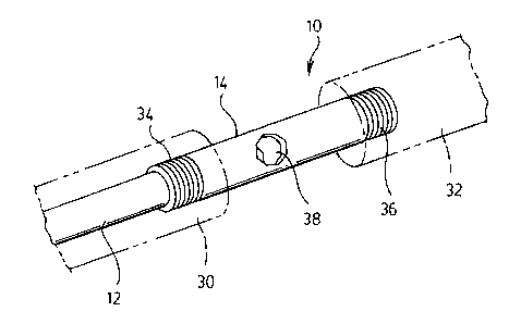
A valve gate is provided for an injection molding manifold having at least one drop defining at least one channel for transporting a flow of plasticized melt therethrough. The valve gate has a pin mounted in the manifold to extend across the channel in a sliding relation. The pin has a transversely extending aperture that aligns with the channel opening the flow. Reciprocating movement of the pin in a direction transverse to the flow of the plasticized melt opens and closes flow thereof.


French Abstract

L'invention concerne un robinet de collecteur de moulage par injection ayant au moins une ouverture définissant au moins un canal pour le transport d'un flux de matière plastique fondue. L'obturateur est muni d'une goupille coulissante montée dans le collecteur, laquelle comporte une ouverture transversale qui s'aligne avec le canal pour laisser passer le flux. Un mouvement de va- et-vient de la goupille dans une direction transversale au flux de matière plastique fondue permet d'ouvrir ou de fermer le débit.

Claims

Note: Claims are shown in the official language in which they were submitted.


Claims
What is claimed is:
1. A valve gate for an injection molding manifold having at least one drop
defining at
least one channel for transporting a flow of plasticized melt therethrough,
said valve
gate comprising:
a pin mounted in said manifold to extend across said channel in a sliding
relation, said pin having a transversely extending aperture that aligns with
said channel,
whereby reciprocating movement of said pin in a direction transverse to the
flow of
said plasticized melt, opens and closes said flows;
a plug having an internal channel through which said plasticized melt flows,
said plug mountable in said at least one channel and having a transversely
extending
aperture, and said pin extends through said transversely extending aperture of
said plug;
and
a tube extending transversely through said transversely extending aperture of
said plug, said pin slidably engaging said tube.
2. A valve gate as claimed in claim 1 wherein said plug has a tip adapted to
engage
said manifold, mounting said plug within said at least one channel.
3. A valve gate as claimed in claim 2 wherein said tip has an internal channel
that
communicates with said internal channel of said plug.
4. A valve gate as claimed in claim 1 wherein said tube is shrink fitted on
said pin.
5. A valve gate as claimed in claim 4 further comprising a pair of protective
sleeves
mounted on opposite ends of said tube.
6. A valve gate as claimed in claim 5 wherein said protective sleeves are
mounted
within a transverse passageway in said manifold to support said pin.
4

7. A valve gate as claimed in claim 6 wherein said plug has a tip adapted to
engage
said manifold, mounting said plug within said at least one channel.
8. A valve gate as claimed in claim 7 wherein said tip has an internal channel
that
communicates with said internal channel of said plug.
9. A manifold for an injection mold, said manifold having at least one drop
defining at
least one channel for transportin a flow of plasticized melt therethrough and
a valve
gate in each of said at least one channel, at least one of said valve gates in
at least one
of said channels comprising:
a pin moveably mounted in said manifold to extend across said channel in a
sliding relation, said pin having a transversely extending aperture that
aligns with said
channel, whereby reciprocating movement of said pin in a direction transverse
to the
flow of said plasticized melt, opens and closes said flow;
a plug having an internal channel through which said plasticized melt flows,
said plug mountable in said at least one channel and having a transversely
extending
aperture, and said pin extends through said transversely extending aperture of
said plug;
and
a tube extending transversely through said transversely extending aperture of
said plug, said pin slidably engaging said tube.
5

Description

Note: Descriptions are shown in the official language in which they were submitted.


CA 02428738 2003-05-13
VALVE FOR AN INJECTION MOLDING MANIFOLD
Field of Invention
This invention relates to a valve pin for an injection molding apparatus. In
particular, this invention relates to a valve pin or gate for enabling and
shutting a flow of
plasticized melt in an injection molding apparatus, wherein the movement of
the I»n is
transverse to the direction of flow of the plasticized melt.
Background of Invention
An injection molding apparatus will have a manifold for delivering the
plasticized
melt from the injection unit to the mold cavity. The manifold will have a
header and may
have a number of drops, each having a valve gate for sequentially injecting
and filling the
mold cavity. As shown in Figure 4, each valve gate 72 has a pin 74 that moves
in the
direction of the flow of plasticized melt to remotely open and close the valve
and thus
IS control the flow of the plasticized melt. United States Patent no.
5,762,855 describes in
detail an apparatus for injection molding utilizing sequential valve gating.
The pin arrangement of the prior art operates effectively for plasticized melt
that
do not include glass fibres. However, if the plasticized melt includes glass
fibres, the pin
location in the manifold drop creates an annular flow channel, reducing the
effective flow
?0 area and increasing material pressure drop and shear, leading to glass
fibre breakage. In
addition, the tip of the pin creates additional shear on the material leading
to further glass
fibre breakage. Further, the operation of the pin in opening and closing the
valve Irate has
a tendency to break the glass fibres and thereby reduce the effectiveness of
the glass
fibres as reinforcement of the finished molded part.
25 Thus, there is a recognized need to provide an apparatus for delivering
plasticized
melt incorporating long glass fibres to a mold cavity without seriously
affecting material
flow and damaging or breaking the fibres.

CA 02428738 2003-05-13
Summary of the Invention
The disadvantages of the prior art are overcome by providing a valve gate
having
a control pin that operates transversely to the flow of the plasticized
material for
minimizing damage to the glass fibres incorporated into the plasticized melt.
According to one aspect of the invention, there is provided a valve gate for
an
injection molding manifold having at least one drop defining at least one
channel for
transporting a flow of plasticized melt therethraugh. The valve gate has a pin
mounted in
the manifold to extend across the channel in a sliding relation. The pin has a
transversely
extending aperture that aligns with the channel opening the t7ow.
Reciprocating
movement of the pin in a direction transverse to the flow of the plasticized
melt opens
and closes flow thereof.
Description of the Drawings
In drawings which illustrate an embodiment of the present invention,
Figure 1 is a perspective schematic view of the valve of the present
invention;
Figure 2 is a tap plan view of the valve of the present invention;
Figure 3 is a side elevational view of the valve of Figure 2; and
Figure 4 is cross-sectional view of a valve gate of the prior art.
?0 Description of the Invention
Referring to Figure 1, a schematic of the control pin assembly IO of the
present
invention is illustrated. The control pin 10 generally comprises a shut-off
pin 12 slidably
mounted within a first tube 14. Shut-off pin 12 is similar to a conventional
pin utilized in
conventional valve gates, except that shut-off pin 12 has a transverse
aperture I6 and thus
?5 will be larger in diameter to allow for the aperture. A conventional driver
17 operatively
mounts to an end opposite the, aperture 16 for effecting reciprocating
movement to open
and close the valve.
Referring to Figures 2 and 3, the manifold section 18 is illustrated. Manifold
section 18 has a first passageway 20, in which a plug 22 is inserted. Plug 22
has an
7

CA 02428738 2003-05-13
internal channel 24, through which plasticized melt flows. A tip 26 threadably
engages
the plug 22 to mount the plug 22 within the internal channel 24. Preferably,
tip 26 has an
internal channel 27 that completes a communication passageway with the mold
cavity.
Plug 22 has a transversely extending aperture that slidingly and sealingly
receives shut-
s oft pin 12.
Manifold section 18 has a transverse passageway 28 that communicates with
first
passageway 20. Two protective sleeves 30, 32 are mounted in the passageway 28.
Sleeves 30 and 32 each has an internal thread for engaging with threads 34, 36
of first
tube 14. First tube 14 has a through hole 38 that is aligned with the first
passageway 20
when engaging the two protective sleeves 30, 32.
Tube 14 is preferably shrink fitted onto the end of shut-off pin 12 to provide
a seal
preventing plasticized melt for leaking therebetween.
In operation, shut-off pin 12 is operative connected with a driver I7 for
moving
the pin I2 in a reciprocating manner. In an open condition, aperture 16 aligns
with the
internal channel 24 enabling flow of plasticized melt therethrough. In a
closed condition,
pin 12 blocks the internal channel 24, preventing or discontinuing flow
therethrough.
Movement of the pin 12 is substantially transverse to the flow direction of
the plasticized
melt.
The operation of the control pin assembly 10 will break glass fibres only when
the
shut-off pin is being moved between the open and closed conditions. In
comparison, the
prior art valve gates will always occupy the flow area of the drop and will
always have
some effect on the breakage of the glass fibres. Thus, the control pin
assembly 10 of the
present invention minimizes the effects of the shut-off pin on material flow
and resulting
fibre length.
The invention has been descc-ibed in an illustrative manner. It is to be
understood
that the terminology, which has been used, is intended to be in the nature of
words of
description rather than of limitation. Many modifications and variations of
the invention
are possible in light of the above teachings. Therefore, within the scope of
the appended
claims, the invention may be practiced other than as specifically described.
3

Representative Drawing
A single figure which represents the drawing illustrating the invention.
Administrative Status

2024-08-01:As part of the Next Generation Patents (NGP) transition, the Canadian Patents Database (CPD) now contains a more detailed Event History, which replicates the Event Log of our new back-office solution.

Please note that "Inactive:" events refers to events no longer in use in our new back-office solution.

For a clearer understanding of the status of the application/patent presented on this page, the site Disclaimer , as well as the definitions for Patent , Event History , Maintenance Fee  and Payment History  should be consulted.

Event History

Description Date
Time Limit for Reversal Expired 2012-05-14
Letter Sent 2011-05-13
Grant by Issuance 2011-04-26
Inactive: Cover page published 2011-04-25
Inactive: Final fee received 2011-02-09
Pre-grant 2011-02-09
Notice of Allowance is Issued 2010-08-09
Letter Sent 2010-08-09
Notice of Allowance is Issued 2010-08-09
Inactive: Approved for allowance (AFA) 2010-07-26
Amendment Received - Voluntary Amendment 2010-04-19
Inactive: S.30(2) Rules - Examiner requisition 2009-10-19
Revocation of Agent Requirements Determined Compliant 2008-12-03
Inactive: Office letter 2008-12-03
Appointment of Agent Requirements Determined Compliant 2008-12-03
Revocation of Agent Request 2008-11-26
Amendment Received - Voluntary Amendment 2008-11-26
Appointment of Agent Request 2008-11-26
Letter Sent 2008-07-14
Request for Examination Received 2008-04-30
Request for Examination Requirements Determined Compliant 2008-04-30
All Requirements for Examination Determined Compliant 2008-04-30
Letter Sent 2004-11-12
Inactive: Delete abandonment 2004-10-08
Inactive: Inventor deleted 2004-09-15
Inactive: Office letter 2004-09-15
Inactive: Abandoned - No reply to Office letter 2004-08-17
Inactive: Correspondence - Formalities 2004-07-07
Inactive: Office letter 2004-06-02
Inactive: Office letter 2004-05-28
Inactive: Single transfer 2004-04-22
Inactive: Correspondence - Formalities 2003-12-23
Inactive: Cover page published 2003-11-16
Application Published (Open to Public Inspection) 2003-11-16
Inactive: First IPC assigned 2003-07-17
Inactive: IPC assigned 2003-07-17
Inactive: Courtesy letter - Evidence 2003-06-17
Inactive: Filing certificate - No RFE (English) 2003-06-12
Application Received - Regular National 2003-06-12

Abandonment History

There is no abandonment history.

Maintenance Fee

The last payment was received on 2010-03-12

Note : If the full payment has not been received on or before the date indicated, a further fee may be required which may be one of the following

  • the reinstatement fee;
  • the late payment fee; or
  • additional fee to reverse deemed expiry.

Patent fees are adjusted on the 1st of January every year. The amounts above are the current amounts if received by December 31 of the current year.
Please refer to the CIPO Patent Fees web page to see all current fee amounts.

Fee History

Fee Type Anniversary Year Due Date Paid Date
Application fee - standard 2003-05-13
Registration of a document 2004-04-22
MF (application, 2nd anniv.) - standard 02 2005-05-13 2005-03-30
MF (application, 3rd anniv.) - standard 03 2006-05-15 2006-03-09
MF (application, 4th anniv.) - standard 04 2007-05-14 2007-03-22
MF (application, 5th anniv.) - standard 05 2008-05-13 2008-03-17
Request for examination - standard 2008-04-30
MF (application, 6th anniv.) - standard 06 2009-05-13 2009-03-17
MF (application, 7th anniv.) - standard 07 2010-05-13 2010-03-12
Final fee - standard 2011-02-09
Owners on Record

Note: Records showing the ownership history in alphabetical order.

Current Owners on Record
DECOMA INTERNATIONAL INC.
Past Owners on Record
RUDOLF ALLAN SCHREMPF
STEVEN JIRO MORI
TODD DEAVILLE
Past Owners that do not appear in the "Owners on Record" listing will appear in other documentation within the application.
Documents

To view selected files, please enter reCAPTCHA code :


To view images, click a link in the Document Description column. To download the documents, select one or more checkboxes in the first column and then click the "Download Selected in PDF format (Zip Archive)" or the "Download Selected as Single PDF" button.

List of published and non-published patent-specific documents on the CPD .

If you have any difficulty accessing content, you can call the Client Service Centre at 1-866-997-1936 or send them an e-mail at CIPO Client Service Centre.


Document
Description 
Date
(yyyy-mm-dd) 
Number of pages   Size of Image (KB) 
Abstract 2003-05-12 1 12
Claims 2003-05-12 2 66
Description 2003-05-12 3 136
Drawings 2003-05-12 2 30
Representative drawing 2003-07-23 1 8
Claims 2010-04-18 2 70
Filing Certificate (English) 2003-06-11 1 158
Request for evidence or missing transfer 2004-05-16 1 101
Courtesy - Certificate of registration (related document(s)) 2004-11-11 1 106
Reminder of maintenance fee due 2005-01-16 1 109
Reminder - Request for Examination 2008-01-14 1 118
Acknowledgement of Request for Examination 2008-07-13 1 177
Commissioner's Notice - Application Found Allowable 2010-08-08 1 164
Maintenance Fee Notice 2011-06-26 1 171
Correspondence 2003-06-11 1 24
Correspondence 2003-12-22 2 88
Correspondence 2004-05-26 1 21
Correspondence 2004-06-01 1 15
Correspondence 2004-07-06 2 49
Correspondence 2004-09-14 1 12
Correspondence 2008-11-25 2 28
Correspondence 2008-12-02 1 15
Correspondence 2008-12-02 1 16
Correspondence 2011-02-08 1 26