Note: Descriptions are shown in the official language in which they were submitted.
CA 02428774 2003-05-15
1
CLOSURE PANwL
The present invention relates to a closure panel such as
found for example in office furniture, in particular, as
a sliding front panel or roller shutter panel of office
cabinets but also kitchen cupboards and as found in
heavier duty applications such as roller shutter doors o~
windows, doors and vehicle entrances,
According to known closure panel designs, the panel
typically consists of a plurality of laterally adjacent
slats, wr=ch are interconnected in a manner such as to
allow relative movement between adjacent Slats into and
out of the plane of a panel in fla= condition so that the
panel may follow an arcuate track or be wound around a
roller.
In a so-called slatt~d panel, this is achieved merely by
providing a plurality of elongate solid, rectangular
section, slats adjacent to one arozher, one pair of
opposed faces providing respective front and .ear wal=s
and the other pair providing respective side walls. The
front walls together d~fine a front wall of the panel
while the rear walls are secured togetr.er by a flexible
substrate, which allows for flexure of the panel when
guided around an arcuate track_ however, such
constructions tend to be too flexible 4o bG commercially
attractive.
zn an alternative arrangement, a plura~~ity of laterally
adjacent slats are interconnected in a manner such as to
enable relative rotation between adjacent slats. This a
CA 02428774 2003-05-15
7
typically by means either of a pivot, hinge, a sliding
joint arrangement, a resilient interconnection member or
other joint arrangement between respective longitudinal
sides of adjacent slats. A typical known arrangement of
this type is shown in Figs. 1 and la. A panel 50
comprises a plurality of slats 52, each having a front
wall 54, a rear wall 56 and respective side walls S8, 60,
one side wall 58 being profiled so as to prcvide an
elongate part-circular socket 59 and she other side wall
having protruding therefrom a rigid strip 61 terminating
in an elongate hollow rib 62. Rib 62 is slidable
longitudinally into socket 59 and is then rotatable
therein. Flexure of the panel is achievable solely by
maans of this relative rotation.
However, in yet another arrar_gement allotaing such
relativE rotation, additional flexure is provided by a
flexible strip extending between adjacent slats as shown
in Fig. 2. Fig. 2 shows a panel 70 comprising a
plurality of hollow slats 72, 86, each having a front
wall 74, a rear wall 76 and respective side walls,
Drofiled as described below. The hollow slats a=a
strengthened by a web 78 extending between the front and
rear walls 74 and 76 respectively.
Each slat 72, 86 of an adjacent pair of slats zs secured
one to the other by a _lexible strip 71 secured to and
extending between adjacent side walls 84 or adjacent
slats at a position rearward of sach front wall 74 and
forward of each rear wall 76. Side walls 84 Gre path
curved so as to ext~nd laterally inwardly fram the =rout
wall 74 to the rear wall 76 so that when the panel is in
CA 02428774 2003-05-15
3
a flat condition as shown in Fig. 2, respective edges of
the front walls 74 may abut one another to provide a
continuous front surface of the panel, whereas, on
flexure of tht flexible strip 71, respective adjacent
strips are capable of rotation relative to one another
out of the plane degined by the abovementioned continuous
front surface.
In addition, one slat of each adjacent pair thereof
(interconnected by flexible strip 71) is provided with a
side wall BO opposite to side wall 84, which side wall BO
is profiled so as to provide an elongate part-circular
socket 82, while the other slat 86 of each interconnected
pair thereof is provided with a side wall 90, having
protruding therefrom a rigid strip 92, terminating in an
elongate hollow rib 8B. As in the embodiment described
with reference to Figs, 1 and la, rib 92 is slideable
longitudinally into socket 82 of an adjacent slat of an
adjacent pair thereof and is then rotatable in socket 82.
Flexure of the panel is therefore achievable by means of
the relative rotation betwEen adjacent pairs of slats 74,
86 and by flexure at the strips 71 between each slat of a
respective pair thereof_
However, it can be aeen that constructions such as those
shown in Figs. 1 and 2 are complicated. so that extrusion
of such constructions is relatively expensive and indeed,
at least for the construction shown in Fig. 2 requires
extrusion of at least two separate materials, one for the
flexible strip 71 and the ether fox the remaining
portions of the slats. Moreover, if a veneer is to be
CA 02428774 2003-05-15
4
provided on the front face of sack a sloe so as to
imp=ove aesthetically the view provided by the front
'ace, then extrusion of a third material will become
necessary.
Moreover, with both of the above ment=oned fo rcis of
panel, it is necessary either to provide a separate
profile including a :candle or means for attachment of a
handle which again adds to the cost of producticn.
The present invention add=esses the problem of providing
a simple panel constructien which is sufficiently stiff
for commercial use whilst providing sufficient
flzxibi=ity for efficient sliding aroand an arcuate track
or storage around a roller, which panel can be pxoduc~d
inexpensively and wrich may allcw the provision of a
separate profile or means for attacr~ent of a handle to
be dispensed with.
Thus, according to the present irwent'_on there is
provided a panel for use as a flexible closure member
capable of travel around an arcuate track or stcrage
around a roller, which panel comprise
a plurality of elongate hollow s'_ats each laterally
adjacent to another, and
a backing material comprising at least one flexible
substrate secured tc a face o~ each slat, the or each
'lexible substrate extending at least longitudinally of
the panel and laterally of the slats frcm a region cf a
face of a first end Slat at one langitudizal erd of the
panel to a region of a face of a second end slat at the
CA 02428774 2003-05-15
other longitudinal end of the panel, so as to connect the
slats to one another,
eacr. slat having an elongate front wall portion and
an elongate rear wall portion opposite to and spaced
apart from tre front wall portion, which front and rear
wall portions are interconnected by opposed, spaced
apart, elongate side wall portiora,
respective front wall portiors being capable of
defining a front face of the panel and respective rear
IO wall port_ors providing the respective faces to which the
flexible substrate is securEd,
one side wall portion of each =espective slat being
profiled so as to provide an elongate protrusion
laterally outwardly or the from and rear wall portions
and the other Side wall portion being profiled so as to
provide ar_ elongate recess laterally inward=y of the
front and rear wall port=on whereby, when the pa:~el is in
a flat condition, respective pre~rusions and recesses
provided by adjacent side wall portions of adjacent slats
are capable of interengagement, thereby providing
stab-lity and stiffness of the panel, but whereby the
respective protrusions are capable of separation out of
engagement with one another so as to alloia 'lexure of the
panel during travel around an arcuar.e track or storage
arour_d a roller.
The slats axe preferably of extruded pl.as~ics material
and are more preferably extruded from different
respective plastics materials, one plastics materia'_
providing a body portion of the slat and the other a
surface portion defining a front face of ~he front wall
portion of each slat, so as to prctride a visible "skin"
CA 02428774 2003-05-15
6
surface of the panel. In this manner, a relatively
_nexpensive material can be employed fcr the body of the
slat, while a more expens'_ve but aesthetically more
pleasing material may be used tc provide a veneer on the
front wall portion of each slat so that the view
presented by the front of the panel may be particularly
at~raczive and may, for example, be of an attractive
colour or provide a mezameric effect in w:zich the panel
changes Colour with the point of viewing. As an
alternative, the slats may be a one-piece extruded
plastics material optionally including therein decorative
material, for example, coloured, especially silver,
flakes.
The protrusions provided by respective side wall portions
of the slats may be defined by regicns of respective side
wa'_- portions which are generally convex while the
recesses may be defined by correspondingly profiled
regions of respective side wall portions which are
generally concave. Generally convex regions of respective
side wall portions cooperate with gene=ally concave
regions of respective side wall portions of adjacent
slats,
In an especially preferred embodiment of suc:~ a
construction, each of the generally convex and generally
cor_cave regions of respective side wall portions of each
slat is preferably defined by a respective generally
central suction of the side wall pcr=ioa spaced from each
of the front and rent wall cord ons oy the slat and
connected thereto by respective recions of the side wall
portions defired by generally planar sections, at least
CA 02428774 2003-05-15
7
the generally planar sections connecting thn central
section to the front wall portion each having an angular
dispositior_ relative to the front or rear wall portion
sLCh as to cooperate with a corresponding planar section
of a side wall portion of an adjacent slat.
Mare preferably, each generally planar section of each
side wall portion which connects the generally central
section to the front wall portion has an angular
disposition generally perpendicular to the front wall
potion. Likewise, more preferably, each generally planar
section of each side wall pert~on which connects the
generally central section to the year wall portion has an
angular disposition generally perpendicular to the rear
wall portion.
in another embodiment of such a construction, the region
of one side wall portion of each slat which is generally
convex and the region of the other side wall portion of
each slat which is generally convex each expend
substar_tially from the front to the rear wall portion.
In an alterna'ivE slat construction, each side wall
portion may include a forward section providing one of a
convex and a concave region and a rearward section
providing the other of a convex and a concave region,
respective adjacent side wall portions of adjacent slats
being correspondingly profiled to allow interengagement
of respective adjacent convex and concave regions with
one another_
CA 02428774 2003-05-15
8
However, it is preferred to provide respective
protrusions and correspondingly profiled recesses by
respective side wall portior_s which have generally planar
sections, a first section protruding (or receding)
laterally from the front wall portion, a second section
protruding (or receding) laterally from the rear wa-1
portzon and a third sectior_ extending between the above
mentioned first and second sections, which third section
is generally perpendicular to at least the front, and
most preferably additionally, the rear wall portions.
In any of the above slat constructions, one of the slats
may be pxofiled so as to be provided with a longitudinal
recess in the front wall portion thereof, which recess is
capable of serving as a har_dle. Alternatively, as a
handle, an aperture may be provided in the front wall
portion through which a user may insert his fi:~gers.
~.n a panel eribodying the ir_vention, z'.~.e bac:~cirq material
may be flexible substrate, preferable a one-piece
flexible substrate, extending essentially over th? entire
panel. Such a flexible substrate is preferal:le a fabric,
more preferably a non-woven fabric.
2~ Alternatively, the backing material comprises a plurality
of flexible substrates, such as a plLrality of tapes of
plastics material.
she flexible substrates may be attached to the slats by
means of an adhesive or by welding, for e~:a~rple, by
thermal or vibration, especially ;lltrasonic, welding.
CA 02428774 2003-05-15
9
A panel ~mbodying the inver_tzon may be adapted to allow
its travel along an arcuate path, especially when the
panel is to provide a side wall opening shutter. For such
shutters, the backing material is preferably a one-piece
3 flexible ssbstrate, e9pecially a fabric.
Alternatively, a panel embodying the invention may be
adapted for storage around a roller to provide a roller
shutter assembly, for example of the balanced Spring
roller type disclosed in GB-A-224172?. For such shutters,
the backing material may then be conveniently provided by
a plurality of tapes o_-' plastics material extending
longitudinally of the panel. Aiterna~ively, the backing
material may be a textile material.
IS
When using a panel construction embodying the invention,
firstly a continuous front face of the panel may be
obtained when the panel is in the flat condition. and
secondly, efficient interengagement can be achieved when
the panel is in the flat condition, thus providing the
panel with a particularly higz stiFfness when in a flat
condition. Moreover, on flexure of the panel, the
respective side wall portions may be easily separated
from one another.
?S
Preferred embodiments of the invention will new be
described with reference to Figs. 3 zo 13 of the
accompanying drawir_gs, Figs. l, la and 2 thereof
illustrating a known const=action as described above.
JO
In the drawings,
CA 02428774 2003-05-15
1U
Fig. 1 shows (on a reduced scale; a cross-section of
a known panel construction in which adjacent slats are
interconnected in a manner such as to enable relative
rotation between adjacent slats, as described above;
Fig. la shows an elevational view of the panel of
rr~ig. 1;
F~.g, 2 shows {on a reduced scale; a cross-section of
a known panel construction alternative to that of Fig. 7.
which again allows rotation between adjacent slats, again
as described above
Fig. 3 shows {on a reduced scale) a section of a
panel embodying the invention;
Fig. 4 shows (on a reduced scale) a plurality of
slats adjacent to one another and employed in the panel
of Fig. 3;
zo
Fig. 5 shows a part of a panel of tre embodiment of ~- --
Fig. 3 in an arcuate track;
Figs. 6 - 8 show a part of a panel of. the etnbodiment
of Fig. 3 in respective flat, bent and completely folded
conditions respectively;
Figs. 9 and i0 show respective parts of alternative
panels similar to that of the embodiment of Fig. 3, but
having slats with side wall portions ~aving respective
different profiles.
CA 02428774 2003-05-15
11
Fig. 11 shows (on a reduced scale) a pair of panels
embodying the invention in use as respective closure
members prov_dirg cooperating side opening shutters.
Fig. 12 shows respective end secr,ions of panels
providing cooperating side opening shuttexs in which the
slats are of the const=uction shown in Fig. 3 but in
which resoeGtive end slats each have a recess in the
front wall to serve as a handle.
Figs. 13a-c show respective front, sectional and
rear views of a panel embodying ~.he invention suitable
for storage on a roller. Fig. 13b is a section on tie
line A-A _:~ Fig. 13a.
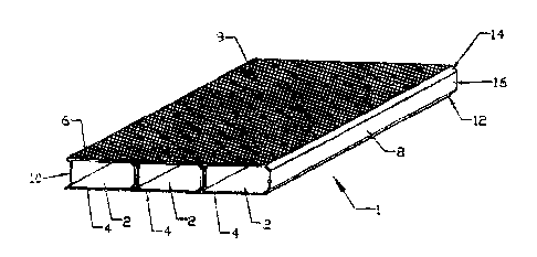
Trus, Fig. 3 shows a section of a panel, generally
indicated as 1, comprising a plurality of elongate slats
2 each having a front wall 4, a rear wall 6 and
respective side walls 8, 10. The respective slats 2 are
~0 interconnected by a flexible substrate 9 secured to rear
faces oi' the rear walls 6 of respective slats 2 so as 'to
::rovide the panel 1.
The flexible substrate 3 is preferably of non-woven
material, especially of bonded polypropylene fibers. Tt
is preferably secured Lo the slats 2 by means of se
adhesive, for example, a polyurethane. Alterl:atively,
the =lexible substrate 9 may be a sheet of plastics
material, such as polyvinyl chloride, polypropylene or a
3~7 polyethylene based ~r~aterial, which may be secured to tae
slats 2 by a hot melt technique such as by weld~.~,g.
especially sonic ~deldinc~.
CA 02428774 2003-05-15
x2
As can be seen from each of Figs. 3 - B, each s;at has a
pair of opposed side walls 8, 10, side wall 8 providing
ar. elongate protrusion defined by respective sections 12,
14, 16 and a side wall 10 providing an elongate recess
defined by respective sections 18, 20 and 22. As can be
seer. particularly from Figs. S - 8, the protrusion
provided by side wall 8 is defined by respective first
and second planar sect,~ors 12 and 14 respective=y
protruding laterally outwardly from front and rear walls
4 and 6. These first and second secticns 12 and 14 are
...~_terconneczed by a third elongate planar section .5
generally perpendicular to front ar_d rear walls ~ and 6.
Likewise, as can be seen clearly from each of Figs. 4
8, the recess provided by side wall 10 of each s_at is
defined by respective elongate first, second and third
sect;ons 18, 20, 22. First and second sections 19 and 20
extend laterally inwardly of the slat from respective
front and rear walls 4 and 6. A third section 22 axtends
betweer_ the first and second sections 18 and 20 in a
direction generally perpendicular to the front and rear
walls 4 and 6 respECtively.
As is demonstrated with particular reference to Fig. 4,
wrier shows respective sets of adjacent slats buc withcut
the flexible substrate, this ccnstruction of panel allows
easy release of the respective panels from one another,
there being no locking of the respective panels one to
the other when they axe in tension; contrast the known
panel construction shown in Figs. 1 and 2.
CA 02428774 2003-05-15
13
Moreover, this generally trapezoidal cor_strucrion of slat
provides a particularly high degree of stiffness to the
panel when in the flat condition, there being a
particularly efficient interengagement between the
respective side walls 8 and 10 providing respective
cooperative protrusions and recesses. This is to be se~n
especially clearly from Fig. 6. Thus, in the flat
condition, the panel is particular=y rigid and stable.
On the other hand, the rlexible substrate and the absence
of any locking in tension allows easy flexure during
travel along an arcuate track 40 (see F'_g. 5). Indeed, it
is not only possible merely to flex Lhe panel (Fig. 7)
but also to fold it, =or example, far storage, so that
respective adjacent slats can lie one above the other
(Fig. 8).
The abovementioned advantages of rigidity and stability
etc may also be obtainable when the respective side wa113
of the s=ats are defined by respective generally convex
side wa1_s while the recesses are defined by
corresponding profiled generally concave side wads.
A particularly neat and simple construction of slat of
this type which is especially easy to manufacture by
extrusion is shown in Fig. 9. The slat, generally
indicated as 42, has ra5pective front (44) and rear (45)
walls interconnected by respective side walks, generally
indicated as 46 and 48, ene of which (46) has a ccnvex
legion and the other of which (48) has a concave region
defined respectively by convex and concave sections 50
and 52 spaced from each of the front and rear walls 44.
CA 02428774 2003-05-15
14
45 of the slat 42 and connected thereto by respective
regions of zh~ side wads defined by planar sections 54 -
57. Each planar sectior_ ~4 - 57 extends perpendicular to
each of she front (44) and rear (46) walls.
The abovementioned advantages awe also achievable when
each side wall includes a forward section providing one
of a convex and a concave section and a wearward section
providing the other of a convex and concave section. Iri
doss section, such side walls may have a generally S-
shaped, or inverted S-shaped, configuration. A part of a
panel the slats of which have side walls so profiled is
shown in Fig. 10. As can be seen, each side wall
generally indicated as 30, 32 of the panel has a short
1~ planar sect-on 23, 24, adjacent to and normal to each of
the front and reax walls 26, 28 respectively and a
generally S-shaped section therebetween. In ore side
wall of the slat, the S-shaped section includes a forward
part, adjacent to the front wall 26, defining a convex
lateral projection 34 and a reaxward part adjGcent to the
rear wall 28 defining a concave lateral recess 36, while
the other, opposed side wall has a forward part defining
a concave lateral recess 38 and a rearward part defining
a convex lateral projection 40. When the panel is in the
flat condition as shown in ig. 10, forward convex
lateral projections 34 engage in cor=esponding forward
concave lateral recesses 38, while rearward convex
lateral projections 40 engage in rearward concave lateral
recesses 36, thus providing a panel which, in the flat
condition, is particularly rigid and stable.
CA 02428774 2003-05-15
Typically, in use, panels embodying the invention may be
fitted betweer_ respective opposed upper and lower tracks
of a cabinet so as to provide respective closure members
as shown in Fig. 10. When the cabinet is in the open_
S condition, the panel may be folded into respective
storage chambers at respective sides of the cabinet after
being pused into respective side Lrack portions 101.
As can be seen from Fig. .1, when the respective panels
10 102, .03 lie adjacent to one another so that the cabinet
is in the fully closed position, it will be necessary for
the user to be able to grip the panels to move them
apart. With a hollow slot construction embodying the
invention, it is possible merely to provide an aperture
15 104 within a front face of one of the slats on each panel
so that the user may merely insert his zingers into the
hcllow space accessible through and thereby draw open. the
respective panels.
~0 Thus, it becomes unnecessary to provide a separate
profiled slat ror this purpose~or to provide means for
attachment or a handle. This represents a considerable
saving in expense.
However, alternatively, as shown in rig. 12, a slat of a
panel may have a from wall profiled ~o as to pxoviCe
therein a recess. Thus, Fig. 12 shows respectiYre end
sections, generally indicated as 60 of pane.is providirLg
cooperating sidE opening shutters in which an end slat 62
of each respective panel section 60 has a front wall 64
profiled so as to provide thereon a recess 66 :which can
b2 used as a handle.
CA 02428774 2003-05-15
16
As an alternative to the panels shown in Figs. 11 and 12
which are adapted to allow travel along an arcuate path
and provide cooperating side shutters, a panel embodying
7 the invention may be adapted for storage around a roller
to provide a vertically opening shutter. Such an
embodiment .s shown in Figs, 13a-c. As can be see from
Fig. 13a, which shown a front view of a panel, this
presents a particularly smooth, continuous suryace to the
IO viewer. Any one (or more) of the slats thereof may be
profiled, ss slat 72, to provide a recess in its front
wall, thus allowing the user to grip the panel; sec
especially Fvg. 13b. As can be seen frem Fig. 13c, which
is a rear view of the panel, respectiTe slats 70 are
15 bound together by a plural=ty of tapes 74 extending
logitudinally of the panel and laterally of the tapes.
The tapes 74 are in spaced apart parallel relationship.
As an alternative, a one,piece flexible substrate such as
a fabric may be employed or_ the backing material.
?0