Language selection

Search

Patent 2428930 Summary

Third-party information liability

Some of the information on this Web page has been provided by external sources. The Government of Canada is not responsible for the accuracy, reliability or currency of the information supplied by external sources. Users wishing to rely upon this information should consult directly with the source of the information. Content provided by external sources is not subject to official languages, privacy and accessibility requirements.

Claims and Abstract availability

Any discrepancies in the text and image of the Claims and Abstract are due to differing posting times. Text of the Claims and Abstract are posted:

  • At the time the application is open to public inspection;
  • At the time of issue of the patent (grant).
(12) Patent: (11) CA 2428930
(54) English Title: AGRICULTURAL MACHINE
(54) French Title: MACHINE AGRICOLE
Status: Deemed expired
Bibliographic Data
(51) International Patent Classification (IPC):
  • A01B 63/16 (2006.01)
  • A01B 61/00 (2006.01)
  • A01B 63/22 (2006.01)
  • A01D 34/00 (2006.01)
(72) Inventors :
  • VIAUD, JEAN (France)
  • GUIET, LIONEL (France)
(73) Owners :
  • DEERE & COMPANY (United States of America)
(71) Applicants :
  • DEERE & COMPANY (United States of America)
(74) Agent: BORDEN LADNER GERVAIS LLP
(74) Associate agent:
(45) Issued: 2006-07-25
(22) Filed Date: 2003-05-20
(41) Open to Public Inspection: 2003-11-23
Examination requested: 2003-05-20
Availability of licence: N/A
(25) Language of filing: English

Patent Cooperation Treaty (PCT): No

(30) Application Priority Data:
Application No. Country/Territory Date
102 22 706.3 Germany 2002-05-23

Abstracts

English Abstract


An agricultural machine includes a wheel at each end of a transverse main
frame with each wheel being carried by a vertically pivotal link to which an
extensible
and retractable actuating device is coupled for effecting vertical adjustment
of the
frame relative to the ground. The upper end of each actuating device is
attached to a
further link which is vertically pivotally mounted to the frame and has its
upward
movement resisted by a frame-mounted spring so as to dampen forces imposed on
the wheel by the terrain. Each further link may be selectively locked to the
frame so as
to eliminate the function of the associated spring.


Claims

Note: Claims are shown in the official language in which they were submitted.


Claims:

1. In an agricultural machine, including a frame having a central section
extending transverse to a normal direction of travel and having opposite ends
respectively joined to upright legs, a wheel-support link coupled to each leg
for pivoting
vertically, a wheel rotatably mounted to each wheel-support link, and an
extensible
and retractable actuating device being coupled between said frame and each
wheel-
support link for selectively adjusting the associated wheel-support link, the
improvement, comprising: each actuating device being coupled to said frame by
a
further link vertically pivotally coupled to said frame and pivotally coupled
to the
actuating device at a location spaced from the connecting between the further
link and
the frame; and a spring being coupled between each further link and said frame
and
resisting upward pivoting movement of said further link.

2. The agricultural machine, as defined in claim 1, wherein each spring is
formed of one of rubber, polyurethane or metal.

3. The agricultural machine, as defined in claim 1, wherein said spring is
a pneumatic reservoir spring mounted for being compressed by upward pivoting
movement of an adjacent one of said further links.

4. The agricultural machine, as defined in claim 1, wherein each further link
is U-shaped and has opposite legs disposed on opposite sides of an associated
one of
the legs of said frame.

5. The agricultural machine, as defined in claim 1, and further including a
lock for selectively securing each further link to said frame so as to remove
the
operation of the associated springs.


Description

Note: Descriptions are shown in the official language in which they were submitted.


CA 02428930 2003-05-20
AGRICULTURAL MACHINE
Field of the Invention
The invention concerns an agricultural machine, particularly a mower, with a
frame and wheels where each of the wheels is connected by a link to the frame,
so
as to pivot vertically, and the position of the link can be varied by means of
an
actuating device, one end of which engages the link.
Background of the Invention
The November 2001 issue of the magazine, "The Furrow", page 20, shows a
rotary mower with several wheels that are connected by means of links to arms
of a
positioning frame. The positioning frame is repositioned by means of a
hydraulic
motor in order thereby to position the operating height of the rotary mower.
Each link
is attached approximately at its center, free to pivot to the particular arm,
and carries
at one end one or two wheels and at the other end a spring that is supported
on the
arm.
The problem underlying the invention is seen in the need to support, on
springs,
other agricultural machines in which an actuating device operates directly on
the link in
the same simple way.
Summary of the Invention
According to the present invention, there is provided an improved wheel
mounting arrangement for an agricultural implement.
An object of the invention is to provide a simple wheel mounting that
preserves a
known wheel mounting arrangement, but provides dampening of loads imposed on
the wheel by the terrain and the like.
This object is accomplished by using, in combination with a conventional
configuration wherein a trailing wheel support arm or link is supported on the
frame
by means of an actuating device, a further spring loaded link inserted between
an
end of the actuator and the implement frame. This results in only a minimal
added
cost for the frame, while the actuating device is merely connected at another
location. Although this configuration is applied predominately to mowers, with
or
without conditioners, its application to sowing machines, ground breaking
machines,
grubbers, and the like is also conceivable.
Springs may be of any conventional configuration, that is, in particular such
made
of rubber, polyurethane or metal. Depending on the material and the connection
of

CA 02428930 2003-05-20
the spring to the further link, the spring can be loaded either in compression
or
tension. Nevertheless, an excessive deflection should be avoided since this
could
lead to an uncontrolled behavior in operation of the agricultural machine
during rapid
operation on very uneven ground.
An example of a spring having suitable characteristics is a pneumatic
reservoir
spring. In particular, it has the advantage that its spring force and
deflection path
can be controlled.
If the further link can be secured to the implement frame, the operation of
the
spring can be deactivated, for example, during operation on the field, and
again
activated for rapid operation on public roads.
Brief Description of the Drawings
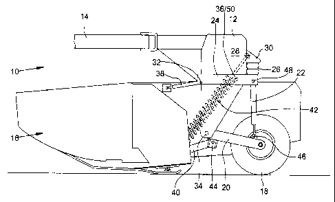
The sole figure of the drawing is a left side elevational view of a towed
implement
embodying an embodiment of the present invention.
Description of the Preferred Embodiment
Preliminarily, it is to be noted that the drawing only shows one of each of
several
components that are described as occurring in pairs, with it to be understood
that the
component not shown is identical to or a right-hand version of the component
that is
shown.
An agricultural machine 10 shown in the drawing includes a main frame 12, a
towbar 14, and an operating unit 16, and pairs of wheels 18, links 20,
actuating
devices 22, further links 24, and springs 26.
The agricultural machine 10 is shown as a so-called mower-conditioner which
mows crop to be harvested that is standing on the ground, processes it, and
deposits
it again on the ground, and at the same time, is towed behind a towing
vehicle, not
shown. Other towed agricultural machines 10, that can be repositioned in their
operating height, could also be used.
As seen in the direction of operation, the frame 12 has the approximate shape
of
an inverted "U". A block 30 is attached, for example, by welding to the rear
side of
each leg 28 of the frame 12. Spaced below and forwardly of each block 30 is a
joint
32. A bearing 34 is located in the lower end region of each leg 28. Between
the
block 30 and the joint 32, the leg 28 is penetrated by a bore 36.
2

CA 02428930 2003-05-20
The towbar 14 is used to connect the frame 12 to the towing vehicle and is
attached to the front side of the frame 12, so as to pivot horizontally, which
however,
is not explained in any further detail since it is sufficiently known.
In the present embodiment, the operating unit 16 is formed by a mower-
conditioner unit that is suspended from frame 12 by upper and lower steering
arms
38 and 40, so as to pivot vertically, and has its weight counterbalanced by
springs 42
so that during operation, only a slight weight is supported by the ground-
engaging
skids carried by the operating unit 16. The operating height of the operating
unit 16
is controlled by the position of the links 20. Otherwise, this operating unit
16 is also
of a known configuration.
On each leg 28 of the frame 12, a wheel 18, a link 20, an actuating device 22,
a
further link 24, and a spring 26 are provided. The further description refers
only to
the left side of the agricultural machine 10, as is visible in the drawing.
Each wheel 18 is located in the rear region of the operating unit 16 and
engages,
free to rotate, the particular link 20.
At its rear region, the link 20 carries the wheel 18, free to rotate, and
engages
with its forward end region, free to pivot vertically, the bearing 34 of the
leg 28. On
the underside of the link 20 in its forward end region, a bearing 44 is
provided for the
connection with the lower steering arm 40. On the upper side of, and near a
rear
end region of the link 20, there is provided a bearing 46 to which is attached
a lower
end of the actuating device 22.
In this embodiment, the actuating device 22 is formed by a hydraulic motor
including a piston rod and cylinder extending essentially in the vertical
direction, with
the rod being coupled at bearing 46 on the link 20. A repositioning of the
length of
the actuating device 22 has the effect of changing the operating height of the
agricultural machine 10.
The further or upper link 24 is formed in an approximate "U" shape and
overlaps,
like a fork, the leg 28 in the horizontal direction. The forward end region of
the link
24 is connected to the frame 12 together with the upper steering arm 38 in the
joint
32, so as to pivot vertically. The rear end region of the upper link 24 is
connected in
a joint in a bearing 48 with the upper end region of the cylinder of the
actuating
3

CA 02428930 2003-05-20
device 22. Between the joint 32 and the bearing 48, the link 24 is provided
with a
bore 50 that can be brought into alignment with the bore 36 in the leg 28 for
the
purpose of receiving a locking pin.
In the preferred embodiment, the spring 26 is made of polyurethane and formed
into a block into which a threaded sleeve, not visible in the drawing, is
integrated.
With its upper side, the spring 26 is in contact with the underside of the
block 30 and
is secured to it by means of a screw inserted into the threaded sleeve. The
underside of the spring 26 is in contact with the upper side of the further
link 24. The
spring 26 is used as a damping member or shock absorber in order to protect
the
frame 12 and the agricultural machine 10 from shocks.
On the basis of the above description, the further link 24 can pivot
vertically about
the joint 32 against the force of the spring 26, so that if necessary, shocks
transmitted over the wheels 18, the link 20, and the actuating device 22 can
be
mitigated by the spring 26.
If the spring function is not to be activated, the aforementioned pin is
inserted
through the bores 36 and 50 so that the further link 24 can no longer pivot.
Having described the preferred embodiment, it will become apparent that
various
modifications can be made without departing from the scope of the invention as
defined in the accompanying claims.
4

Representative Drawing
A single figure which represents the drawing illustrating the invention.
Administrative Status

For a clearer understanding of the status of the application/patent presented on this page, the site Disclaimer , as well as the definitions for Patent , Administrative Status , Maintenance Fee  and Payment History  should be consulted.

Administrative Status

Title Date
Forecasted Issue Date 2006-07-25
(22) Filed 2003-05-20
Examination Requested 2003-05-20
(41) Open to Public Inspection 2003-11-23
(45) Issued 2006-07-25
Deemed Expired 2009-05-20

Abandonment History

There is no abandonment history.

Payment History

Fee Type Anniversary Year Due Date Amount Paid Paid Date
Request for Examination $400.00 2003-05-20
Application Fee $300.00 2003-05-20
Registration of a document - section 124 $100.00 2003-08-28
Maintenance Fee - Application - New Act 2 2005-05-20 $100.00 2005-05-09
Final Fee $300.00 2006-04-03
Maintenance Fee - Application - New Act 3 2006-05-22 $100.00 2006-05-08
Maintenance Fee - Patent - New Act 4 2007-05-22 $100.00 2007-04-30
Owners on Record

Note: Records showing the ownership history in alphabetical order.

Current Owners on Record
DEERE & COMPANY
Past Owners on Record
GUIET, LIONEL
VIAUD, JEAN
Past Owners that do not appear in the "Owners on Record" listing will appear in other documentation within the application.
Documents

To view selected files, please enter reCAPTCHA code :


To view images, click a link in the Document Description column. To download the documents, select one or more checkboxes in the first column and then click the "Download Selected in PDF format (Zip Archive)" or the "Download Selected as Single PDF" button.

List of published and non-published patent-specific documents on the CPD .

If you have any difficulty accessing content, you can call the Client Service Centre at 1-866-997-1936 or send them an e-mail at CIPO Client Service Centre.


Document
Description 
Date
(yyyy-mm-dd) 
Number of pages   Size of Image (KB) 
Representative Drawing 2003-07-24 1 12
Abstract 2003-05-20 1 16
Description 2003-05-20 4 174
Claims 2003-05-20 1 36
Drawings 2003-05-20 1 16
Cover Page 2003-10-28 1 39
Representative Drawing 2006-07-04 1 12
Cover Page 2006-07-04 1 40
Correspondence 2003-06-16 1 24
Assignment 2003-05-20 2 83
Assignment 2003-08-28 2 93
Correspondence 2006-04-03 1 33