Note: Descriptions are shown in the official language in which they were submitted.
CA 02429129 2003-05-30
SHAVING SYSTEM AND METHOD
This is a division of co-pending commonly owned Canadian Patent Application
No. 2,250,004 filed April 8, 1997.
BAClCGItOUND OF THE INVENTION
The invention relates to shaving systems having handles and replaceable
cartridges.
Shaving systems often consist of a handle and a replaceable cartridge in which
one or more blades are mounted in a plastic housing. After the blades in a
cartridge
have become dull from use, the cartridge is discarded, and replaced on the
handle with
a new cartridge. In some shaving systems the blades are resiliently mounted
with
respect to the cartridge housing and deflect under the force of skin contact
during
shaving. In some shaving systems the connection of the cartridge to the handle
provides a pivotal mounting of the cartridge with respect to the handle so
that the
cartridge angle adjusts to follow the contours of the surface being shaved. In
such
systems, the cartridge can be biased toward an at rest position by the action
of a
spring-biased plunger (a cam follower) carried on the handle against a cam
surface on
the cartridge housing.
SUMMARY OF THE INVENTION
In general, in one aspect according to the parent application, there is
provided
a replaceable shaving cartridge having a housing carrying blades, a guard, a
cap, and
a camming surface. The cartridge also includes an interconnect member having a
pivotal support structure that pivotally supports the housing and a base
structure
adapted to be removably and fixedly attached to a handle. The interconnect
member
provides access to the camming surface by a spring-biased cam follower on the
handle.
In general, in another aspect according to the parent application there is
provided a replaceable shaving cartridge having a housing carrying blades, a
guard,
and a cap. The cartridge also includes an interconnect member having a pivotal
-1-
CA 02429129 2003-05-30
support structure that pivotally supports the housing about a pivot axis and a
base
structure adapted to be removably and fixedly attached to an extension at an
end of
a handle. The handle extension has outer side surfaces, and the base structure
has
a recess with inwardly directed side surfaces that engage a sufficient number
of the
outer side surfaces on the handle extension so as to immovably position the
base
structure with respect to the handle extension. The base structure also has an
opening
to the recess along an axis that is nonparallel with respect to the pivot
axis.
In general, in another aspect according to the parent application, there is
provided a method of making a replaceable shaving cartridge. A housing for
carrying
blades, an interconnect member having a pivotal support structure and a base
structure adapted to be removably and fixedly attached to a handle are
provided. The
pivotal support structure is inserted into a recess in the housing. The
pivotal support
structure is retained in the recess.
Implementations of the invention may include one or more of the following
features. The retaining step includes snap fitting and/or adding a clip. The
blades may
be added to the housing before adding a clip to retain the blades with the
clip.
The present invention on the other hand may be considered as providing a
shaving handle which includes an elongated hand gripping structure having an
outwardly directed upper surface and generally opposite thereof an outwardly
directed
lower surface, and a cartridge support structure extending from an end of the
hand
gripping structure. The elongated hand gripping structure has first and second
gripping portions, each gripping portion comprising an elastorneric plastic
outer
gripping layer and a nonelastomeric plastic support layer thereunder having
extensions
that are press-fitted into the elongated hand gripping structure, the
elastomeric outer
gripping layer being molded to the nonelastomeric support layer and overlying
a major
portion of the nonelastomeric support layer. ~ne of the gripping portions is
in
overlying relation to the upper surface of the elongated hand gripping
structure, and
another of the gripping portions is in overlying relation to the lower surface
of the
elongated hand gripping structure. The first and second gripping portions are
attachable along inwardly oriented axes to attach to the hand gripping
structure,
-2-
CA 02429129 2003-05-30
whereby the hand gripping structure is sandwiched between the first and second
gripping portions.
In another aspect the present invention may be considered to provide a shaving
razor handle comprising an elongated hand gripping structure, and a cartridge
support
structure extending from an end thereof. The elongated hand gripping structure
includes a gripping portion comprising an eiastomeric plastic outer gripping
layer and
a nonelastomeric plastic support layer thereunder having extensions that are
press-fitted into the elongated hand gripping structure. The elongated hand
gripping
structure is made of plastic and defines a recess, and further includes a
weight in the
recess.
In yet another aspect thereof, the present invention may be considered to
provide a shaving handle comprising an elongated lland gripping structure and
a
cartridge support structure extending from an end of the hand gripping
structure. The
elongated hand gripping structure further comprises an elongated first handle
portion
comprising a plastics material, with the elongated handle portion defining a
weight
receiving region. A metal weight is disposed in the weight receiving region.
The
elongated handle portion comprises an elastomeric plastic outer gripping layer
molded
with a nonelastomeric plastic support layer thereunder having extensions
attached into
the weight.
In yet another aspect the present invention contemplates a shaving razor
handle
shank comprising first and second handle members defining gripping surfaces
for a
hand of a user, each handle member having a plurality of inwardly extending
posts,
and a weight having a plurality of location and securement apertures. The
weight is
retainedly sandwiched between the first and second handle members, and the
first
handle member comprises an elastomeric plastic outer gripping I<~yer molded
with a
nonelastomeric plastic support layer thereunder having the inwardly extending
posts.
In yet another aspect thereof the present invention contemplates a shaving
handle comprising an elongated hand gripping structure, with a cartridge
support
structure extending from an end of said hand gripping structure. The elongated
hand
gripping structure has a recess and a metal weight received in the recess, and
includes
-3-
CA 02429129 2003-05-30
a gripping portion comprising an elastomeric plastic outer gripping layer
molded with
a nonelastomeric plastic support layer thereunder having extensic:ns that are
secured
in the weight.
In general, in another aspect, the invention features a replaceable shaving
cartridge having a housing carrying blades, a guard, and a cap. The cartridge
also
includes an interconnect member having a base structure adapted to be
removably and
fixedly attached to a handle extension that extends from an end of a handle
along an
extension axis. The handle extension has outer side surfaces and an
asymmetrical
section in a plane through the side surfaces perpendicular to the extension
axis. The
base structure has a recess that mates with the extension and has inwardly
directed
side surfaces that engage a sufficient number of the outer side surfaces along
the
asymmetrical extension so as to immovably position the base with respect to
the
extension and to ensure proper orientation of the housing with respect to the
handle.
The base structure has an opening to the recess along an axis that is
perpendicular to
the plane.
Certain implementations of the invention include one or more of the following
features.
In certain implementations: the housing has a substantially unobstructed
rinsing
region under the blades; the pivotal support structure has a pivot axis in
front of the
blades in the region of the guard. The shape of the recess in the base may be
a
trapezoid, have six sides and/or be flat in a direction parallel to the
blades.
In certain implementations: the base structure is snap fitted onto the handle;
the base structure has a detent and the handle has a mating depression adapted
to
receive the detent; alternatively the handle has a detent and the base
structure has
a mating depression adapted to receive the decent; plural detents and
depressions are
used. Alternatively, the base structure is latchably secured to the handle.
In certain implementations: the housing and the interconnect member are made
from separate pieces of plastic. Alternatively, the housing and the
interconnect
member are made of the same piece of plastic, and the pivotal support
structure is
provided by a living hinge. Alternatively, the pivotal support structure is
provided by
-4-
CA 02429129 2003-05-30
a flexible plastic hinge portion that is made of material that is mare
flexible than the
housing and connects the housing and interconnect member at a pivot region.
In certain implementations: the pivotal support structure of the interconnect
member includes two arms having ends retained in recesses with openings at two
sides
of the housing; the ends of the arms snap into the recesses of the housing;
the
recesses are covered by clips to retain the ends of the arms within the
recesses; the
arms have lower surfaces that slide on upwardly-directed arcuate surfaces on
the
housing.
In certain implementations: the housing has a caroming surface for receiving a
cam follower surface on a spring-biased plunger from the interconnect member;
the
interconnect member has an opening to receive the spring-biased plunger; the
caroming surface permits pivoting in only one direction from a rest position
or permits
different amounts of pivoting forward and backward from the rest position; the
housing
also has front and back stop surfaces that interact with the interconnect
member.
In certain implementations: the blades are loaded into the housing from a top
side of the housing; the blades are retained in the housing by clips that
retain the
interconnect member at a bottom side of the housing; the housing carries three
blades; the blades are spring biased (e.g., the blades may be resiliently
supported in
the housing by spring arms integral with the housing; the guard is made of an
elastomer and has flexible fins to engage the user°s skin.
In general, in another aspect, the invention features a shaving razor handle
having an elongated hand gripping structure and a cartridge support structure
extending from an end of the hand gripping structure. The cartridge support
structure
has outer side surfaces that mate with inwardly directed surfaces of a recess
on a
cartridge and an end surface with an opening. A spring-biased plunger is
retained in
the cartridge support structure and extends through the opening of the
cartridge
support structure.
Certain implementations of the invention may include one or more of the
following features.
In certain implementations: the outer side surfaces provide an asymmetrical
-5-
CA 02429129 2003-05-30
shape to ensure proper orientation of the cartridge with respect to the
handle; the
spring-biased plunger is guided by a slot in the cartridge support structure;
an ejector
and snap fit ejector button are used to eject the cartridge; the ejector
button has an
inclined surface to facilitate attachment to the cartridge support structure;
the ejector
button slides on a guide surface in the cartridge support structure when
pushing the
ejector; the cartridge support structure has a track, and the ejector button
has a
groove that slides on the track.
In certain implementations: the plunger and the ejector are biased in opposite
directions by a spring; the plunger has a stop which retains the plunger
within the
cartridge support structure; the plunger has an arm with an inclined surface,
the
inclined surface and the stop extending above the plunger and being retained
in the
slot in the cartridge support structure to guide the plunger; the stop has an
inclined
surface to permit the stop to be inserted into the cartridge support
structure; the
plunger has a rear guide member to further guide the plunger.
In certain implementations: the first end ofthe spring biases the plunger
against
the stop, and a second end of the spring biases the ejector against a back
surface of
the cartridge support structure; the ejector button and the cartridge support
structure
have spring support portions to capture and guide the spring.
In certain implementations: the ejector is a U-shaped clip having ejector arms
and narrower portions that engage the ejector button, and the cartridge
support
structure has a mating guide surface along which the ejector arms and the
narrower
portions slide.
In certain implementations: the cartridge support structure and the elongated
gripping structure are made of a single piece of plastic. ,4lternatively, the
cartridge
support structure and the elongated gripping structure are made from separate
pieces
of plastic.
In general, in another aspect, the invention features a shaving razor handle
having an elongated hand gripping structure and a cartridge support structure
extending from an end of the hand gripping structure. The elongated hand
gripping
structure includes a gripping portion including an elastomeric plastic outer
gripping
-6-
CA 02429129 2003-05-30
layer and a nonelastomeric plastic support fayerthereunder having extensions
that are
press-fitted into the elongated hand gripping structure.
In certain implementations: the elongated hand gripping structure is made of
plastic and defines a recess in which a weight is disposed; the plastic is
metallic colored
plastic.
In general, in another aspect, the invention features a method of making a
shaving razor handle. An elongated hand gripping structure and an attached
cartridge
support structure extending from an end of the elongated hand gripping
structure and
having a recess therein with an inwardly directed stop surface are provided. A
spring
and a plunger having an outwardly directed stop surface are inserted into the
recess
until the outwardly directed stop surface passes the inwardly directed stop
surface and
is retained by the inwardly directed stop surface.
Certain implementations of the invention may include one or more of the
following features: the ejector is inserted into the recess; an ejector button
is inserted
into the cartridge support structure to push the ejector.
In general, in another aspect, the invention features a razor including a
handle
and a replaceable shaving cartridge including a pivota6 housing and an
interconnect
member. The housing carries blades, a guard, a cap, and has a carnming
surface. The
interconnect member has a pivotal support structure that pivotally supports
the
housing and a central base structure having a recess and an opening from the
recess
facing the camming surface. The handle has a cartridge support structure
shaped to
mate with the recess and a spring biased plunger with a cam follower surface
extending from the cartridge support structure and through the opening to act
on the
camming surface to bias the housing.
In general, in another aspect, the invention features a razor having a
replaceable shaving cartridge including a housing and an interconnect member.
The
housing carries at least one blade, a guard, and a cap. The interconnect
member has
a pivotal support structure and a central base structure with a recess. A
handle has
a cartridge support structure including an extension shaped to mate with the
recess,
and a stepped portion has the same shape as the central base structure so as
to
CA 02429129 2003-05-30
continue the shape from the cartridge support structure to the central base
structure.
Certain implementations of the invention may include one or more of the
following features: the central base structure may be flat along an axis that
is parallel
to the blade, and may also have a curved or beveled shape.
Other advantages and features of the invention will be apparent from the
detailed description of preferred embodiments thereof and from the claims.
BRIEF DESCRIPTI~N OF THE DRI~VIIINC~S
FIG. 1 is a perspective view of a shaving razor according to the invention.
FIG. 2 is a perspective view showing a handle and a replaceable cartridge of
the
FIG. 1 razor separated from each other.
FIG. 3 is an exploded view of the components of the FIG. 2 handle.
FIG. 3A is a diagrammatic sectional view, taken at 3A--3A of FIG. 2, of the
FIG.
2 handle.
FIG. 4 is an exploded view of the components of the FIG. 2 replaceable
cartridge.
FIG. 4A is an exploded sectional view, taken at 4A--4A of FIG. 14, of the
components of the FIG. 2 replaceable cartridge.
FIG. 5 is a partial plan view showing a cartridge support structure at the end
of
the FIG. 2 handle.
FIG. 6 is an elevation of a plunger of the FIG. 2 handle.
FIG. 7 is a partial sectional view, taken at 7--7 of FIG. 5, of the FIG. 5
cartridge
support structure.
FIG. 8 is a sectional view, taken at 8°-8 of FIG. 5,, of the FIG. 5
cartridge support
structure.
FIG. 9 is a partial sectional view, take:~ at 9--9 of FIG. 5, of the FIG. 5
cartridge
support structure.
FIG. 10 is a plan view of an ejector used in the FIG. 5 cartridge support
structure.
FIG. 11 is a perspective view of the FIG. 6 plunger.
_g_
CA 02429129 2003-05-30
FIG. 12 is an elevation of an ejector button used in the FIG.. 5 cartridge
support
structure.
FIG. 13 is an elevation of the FIG. 2 replaceable cartridge.
FIG. 14 is a plan view of the FIG. 13 replaceable cartridge.
FIG. 15 is a bottom view of the FIG. 13 replaceable cartridge.
FIG. 16 is a side view, partially broken away, showing a housing of the FIG.
13
cartridge in an unbiased pivotal position with respE:ct to a base structure of
the
cartridge prior to connection to a handle.
FIG. 17 is a side view, partially broken away, of the FIG. 13 cartridge in a
biased
position after connection to a handle.
FIG. 18 is a side view, partially broken away,, showing the range of pivotal
movement of the FIG. 13 replaceable cartridge.
FIG. 19 is a sectional view of an extension of the FIG. 2 handle.
FIG. 20 is a sectional view of an alternative embodiment of an extension of
the
FIG. 2 handle.
FIGS. 21 and 22 are side views of alternative embodiments of cartridges having
different pivotal support structures.
DESCRIPTION OP THE PREFERRED EMBODIMENTS
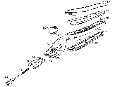
Referring to FIGS. 1 and 2, shaving razor 10 includes handle 12 and
replaceable
shaving cartridge 14. As shown in FIG. 2, cartridge I4 is removable from
handle 12.
Cartridge 14 includes housing 16, which carries three blades 18, guard 20 and
cap 22.
Cartridge 14 also includes interconnect member 24 on which housing 16 is
pivotally
mounted. Interconnect member 24 includes base 27, which removably and fixedly
attaches to asymmetrical extension 26 (FIG. I9) on handle I2, and two arms 28
that
pivotally support housing 16 at its two sides.
Referring to FIG. 3, handle 12 includes metallic colored plastic component 30
as
a primary structural member on which the remaining components are mounted.
Elongated portion 32 of component 30 has recess 34 for receiving metal (e.g.,
zinc)
weight 36, which is sandwiched between plastic gripping portions 38 and 40 to
provide
-9-
CA 02429129 2003-05-30
a hand-gripping structure in the completed unit. Plastic gripping portions 38
and 40
are made of an elastomeric plastic outer gripping layer 37 (e.g.,
thermoplastic
elastomer) and a nonelastomeric plastic support layer 39 (e~.g., of
acrylonitrile
butadiene styrene) thereunder made by two-color molding. The nonelastomeric
plastic
support layer has extensions 41 that are press-fitted into weight 36 in
elongated
portion 32. FIG. 3A illustrates the undeformed shape of extension 41 (in
phantom)
and the interference fit made by it at projection 43.
Cartridge support structure 42 extends from the end of elongated portion 32.
It includes trapezoid shaped extension 26 (see FIG. 19) and the components
that
provide a spring-biased plunger action for biasing of housing 16 relative to
interconnect
member 24. It also includes components that provide for ejection of cartridge
14 from
handle 12.
Spring-biased plunger 44, spring 46, and U-shaped ejector 48 are received
within recess 49 of cartridge support structure 42. Fjector button 50 is
received in
opening 52 on the top surface of support structure 42 and has bottom
extensions 54
that are received within rectangular region 56 at the back narrow portion of
ejector 48.
Referring to FIGS. 4, 4A and 15, housing 16 of cartridge 14 has inwardly
facing
slots 58 in side walls 60 for receiving the edges of the base portions 59 of
blades 18
and respective resilient arms 62 (FIG. 15) on which each blade 18 is
resiliently
supported. Blades 18 are located in a substantially unobstructed region 64
between
side walls 60 to provide for ease of rinsing of the cartridge during use.
Cap 22 provides a lubricious shaving aid and is received in slot 66 at the
rear of
housing 16. Cap 22 may be made of a material comprising a mixture of a
hydrophobic
material and a water teachable hydrophilic polymer material, as is known in
the art and
is described, e.g., in U.S. Patents Nos. 5,113,585 and 5,454,164. Guard 20
includes
a finned elastomeric unit mounted at the front of housing 16 to engage and
stretch the
user's skin; other skin engaging protrusions, e.g., a=. described in U.S.
Patent No.
5,191,712 can be used. Clips 68 are secured at the irespective sides of
housing 16
inside of raised edges 70 of side walls 60 in order to retain blades 18 within
housing
16 and to locate the cutting edges of the spring-biased blades at a desired
exposure.
-10-
CA 02429129 2003-05-30
Clips 68 also wrap around the bottom of housing 16 and prevent the removal of
pivotal support ends 72 of arms 28 of interconnect member 24. Base structure
27 has
an opening 74 at the top through which spring-biased plunger 44 of the handle
passes
to act on a cam surface (not shown in FIG. 4) on the bottom of housing 16.
Base
structure 27 may have a curved or beveled shape.
FIGS. 5-12 and 19 show the details of plunger 44, ejector 48, button 50, and
cartridge support structure 42. Referring to FIG. 5, recess 49 within
cartridge support
structure 42 has wide front portion 76 for receiving arms 78 of ejector 48
(FIG. 10)
and a narrower portion 80 for receiving narrower portion 82 of ejector 48.
Rectangular
region 56 at narrow portion 82 of ejector 48 is generally aligned with opening
52 at the
upper surface of support structure 42, though rectangular region 56 is movable
with
respect to opening 52 along slide axis 83 as ejector 48 is pushed outward by
ejector
button 50.
Referring to FIGS. 8 and 12, each extension S4 of ejector button SO has an
outwardly directed groove 84 that slides on a respective track 86 within
opening 52
along axis 83. The upper surfaces 85 defining grooves 84 slide on the upper
surfaces
89 of tracks 86, and the lower surfaces 91 defining groves 84 effect capture
on or abut
the lower surfaces 93 of tracks 86. Extensions 54 have inclined surfaces 87
that coact
with the curved upper corners of tracks 86 to deflect extensions 54 inward as
button
50 is inserted into cartridge support structure 42. When grooves 84 on
extensions 54
align with tracks 86, extensions 54 substantially return to their undeflected
position
and lock ejector button 50 in place within opening 52. Ejector 48 is placed
within
recess 49 before button 50 is inserted so that the ends of extensions 54 will
be located
within rectangular region 56 so as to retain ejector 48 within cartridge
support
structure 42. Extensions 54 push against surfaces 94 of ejector 48 when
ejector
button 50 is pushed toward the end of handle 12. After button 50 has been
inserted,
upper vertical surfaces 96 of extensions 54 sit within the space between upper
surfaces
98 of opening 52.
Spring 46 (FIG. 3) extends through the space between extensions 54 and is
guided by the curved lower surface of spring guide 90 on button 50. As shown
in FIG.
-1 i-
CA 02429129 2003-05-30
8, the lower surface defining recess 49 also has a curved central portion 92
to receive
and guide spring 46.
As shown in FIGS. 6 and i1, plunger 44 has flat body 7.06, cylindrical rear
extension 100 for receiving spring 46 (FIG. 3), curved front cam follower
portion 102
for acting on the camming surface 136 (FIG. 18) of housing 16, side arms 104,
and
aligned rear guide portions 108. Flat body 106 is positioned within the flat
front
portion of recess 49 (FIG. 6). The portions of side arms 104 and aligned rear
guide
portions 108 above and below body 106 are located within slots 110, 112
located on
both sides of asymmetrical extension 26. Side arms 104 have stop surfaces 114
that
prevent forward movement of plunger 44 beyond the front end of slot 110 or
112. The
portions of side arms 104 and guide portions 108 above and below recess 49
within
slots 110, 112 act as guides to guide the sliding action of plunger 44 along
axis 83.
Side arms 104 have inclined surfaces 120 to cause downward biasing of arms
104 when plunger 44 is inserted into recess 49 until stop surfaces 114 advance
past
the front ends of slots 110, 112 and stop surfaces 114 snap into position
within the
respective slot. Because slots 110, 112 are provided on both sides of
asymmetrical
extension 26, plunger 44 can be inserted in either position orientation, with
the stop
surface 114 directed into slot 110 or 112.
Referring to FIGS. 5 and 9, one surface of asyrr~metrical extension 26
includes
depressions 122 for receiving detents within base structure 27 of cartridge 14
in order
to retain cartridge 14 on extension 26.
In manufacture of handle 12, the hand gripping components are assembled by
first inserting weight 36 into recess 34, and then press-fitting extensions 41
of
components 38, 40 into aligned apertures in weight 36. Weight 36 and
components
38, 40 are locked in place by the interference fit between extensions 41 and
projections 43, and elastomeric layer 37 deforms to provide a seal between the
side
walls of elongated portion 32 of plastic component 30 and weight 36. (FIG. 3A
shows
the undeformed shapes of the components in phantom.)
In assembling the components of cartridge support structure 42 at the end of
handle 12, ejector 48 is first inserted into recess 49. Spring 46 and plunger
44 are
-1 z-
CA 02429129 2003-05-30
then inserted. Inclined surfaces 120 of side arms 104 are biased during
insertion
toward the middle of the recess and then snap into slot 110 or 112 (depending
on
plunger orientation) locking plunger 44, spring 46, and ejector 48 in place in
cartridge
support structure 42. Spring 46 acts both to bias ejector 48 backward against
the
surfaces of recess 49 and button extensions 54 and to bias plunger 44 forward,
stop
surfaces 114 being biased against the forward edges of slot 110 or 112. Button
50 is
inserted into opening 52 after ejector 48 has been inserted iota position.
Inclined
surfiaces 87 are biased inward by the curved upper portions of rails 86, and
ejector
button 50 is snapped into place with tracks 86 being located within grooves
84.
FIGS. 13-18 show further details of replaceable cartridge 14 and its pivotal
movement. Referring to FIG. 13, interconnect member 24 is shown assembled to
housing 16 with pivotal support ends 72 retained by clips 68. It is seen that
base
structure 27 has a trapezoidal shaped recess 130 that has the same shape as
extension 26 and mates with extension 26.
Referring to FIG. 15, housing 16, shown before the other cartridge components
have been assembled on it, has recesses 131 in which the pivotal support ends
72 on
the ends of arms 28 are received. Arms 28 deflect as support ends 72 are
inserted
through the openings to recesses 131 and then snap back to an undeflected
orientation
after ends 72 are within recesses 131 to retain ends 72 in place.
Referring to FIGS. 4A and 9, detents 132 within recess 130 of base 27 mate
with
depressions 122 of asymmetrical extension 26. At the top of recess 130 is
opening 74
which permits spring-biased plunger 44 to extend through base 27 and to
interact with
camming surface 136 on the bottom of housing 16.
Referring to FIGS. 16-18, it is seen that each pivotal support end 72 has a
lower
curved surface 138 that slides on upper curved surface 140 of housing 16,
providing
a pivot axis at the center of a circle that includes surface 140. The pivot
axis thus is
in front of the blades in the region of guard 20. FIG. 16 shows housing 16 in
an
unbiased position in which pivotal support ends 72 support the front surface
of guide
wall 162. FIG. 17 shows the forwardly biased position for housing 16, in which
case
the forward surface of pivot support ends 72 are pushed up against a forward
wall
-13-
CA 02429129 2003-05-30
portion of housing 16. This is the at rest position for housing 16 prior to
shaving. The
forwardfy-biased at rest position is achieved by contouring camming surface
136 so
that plunger 44 having cam follower surface 102 has an at rest position near
the front
of housing 16, as shown in FIG. 18.
FIG. 18 shows the range of pivotal motion for housing 16. During shaving, cap
22 will initially contact the user's skin, and housing 16 will pivot clockwise
and generally
follow the contours of the user's face, being biased by plunger 44~. The cap
up initial
orientation will cause the blade closer to cap 22 to initially be pushed
against the skin
more than the blades closer to the guard. However, the pivot at the region of
the
guard and the light return force cause the cartridge to be "guard heavy"
during
shaving, with a higher load on the guard than the cap. The three blades are
provided
with progressive initial exposures, defined as the perpendicular distance or
height of
the blade edge measured with respect to a plane tangential to the skin
contacting
surfaces of the cartridge components immediately in front of and behind each
blade.
In particular, the primary blade has a negative initial exposure, the second
blade has
zero initial exposure, and the third biade has positive initial exposure. The
spring
constants and preloads for the blades are the same, and the blades have
"progressive
force" distribution during shavings i.e., the force on the third blade is
greater than the
force on the first blade, and the force on the second blade is intermediate to
the forces
on the first and third blades or equal to the force on either the first or
third blade. It
is believed that beneficial shaving results are achieved when cartridges with
three
resiliently mounted blades exhibit, during shaving, such a progressive force
pattern.
OTHER EMBODIMENTS
Other embodiments of the invention are within the scope of the appended
claims. The base structure could be held on the housing with a releasable
latch. The
blades could be loaded from the bottom instead of the top. The cartridge
support
structure could be made as a unit separate from the handle and attached to it.
In
place of trapezoidal extension 26 (FIG. 19), a six-sided extension 226 (FIG.
20), or
other asymmetrical shape could be employed.
-14-
CA 02429129 2003-05-30
The pivotal connection could be provided by pins in respective holes, shell
bearings, and other techniques. E.g., referring to FIG. 21, the pivotal
support
structure could be provided by a flexible plastic hinge portion 200 that is
made of
material that is more flexible than the housing 202 and connects the housing
202 and
interconnect member 204 at a pivot region 206; these components could be made
by
two-color molding. Alternatively, referring to FIG. 22, the housing 208 and
the
interconnect member 210 may be made of the same piece of plastic, and the
pivotal
support structure may be provided by a living hinge 212. A living hinge could
also be
used with housings and interconnect members of different plastics.
-I5-