Note: Descriptions are shown in the official language in which they were submitted.
CA 02429237 2012-09-24
66742-803
1
METHOD AND APPARATUS FOR
MONITORING HEART RATE AND ABNORMAL RESPIRATION
BACKGROUND OF THE INVENTION
The present invention relates generally to implantable medical devices and
more particularly to implantable medical devices intended for use in
monitoring a patient's
heart rhythm and abnormal respiration.
Implantable pacemakers and cardioverters monitor the heart's rhythm in order
to detect arrhythmias and deliver appropriate therapies to terminate detected
arrhythmias. In
conjunction with this function, the ability of the device is to store
information with regard to
monitored heart rhythms has dramatically increased over the past two years.
Examples of
implantable pacemakers and defibrillators which have the capability of storing
information
related to monitored heart rhythms include U.S. Patent No. 5,330,513 issued to
Nichols et al.,
U.S. Patent No. 6,129,745 issued to Sun et al. and U.S. Patent No. 5,447,519
issued to
Peterson. In addition, there have recently been developed subcutaneously
implantable
monitoring devices that do not deliver any anti-arrhythmia therapies to the
heart but simply
store information regarding a patient's heart rhythms for later uplink to an
external device.
Such devices are disclosed in U.S. Patent No. 5,851,221 issued to Rieder et
al., U.S. Patent
No. 5,535,752 and U.S. Patent No. 5,564,434 issued to Halperin et al.
In conjunction with implantable devices as described above, information
stored relating to a patient's heart rhythm may include information relating
to heart rate trends
over time, as disclosed in U.S. Patent No. 5,088,488 issued to Markowitz et
al., U.S. Patent
No. 4,364,397 and U.S. Patent No. 4,360,030 issued to Citron et al., as well
as information
relating to heart rate variability over time, as disclosed in U.S. Patent No.
5,957,861 issued to
Combs et al., U.S. Patent No. 6,045,513 issued to Stone et al. and U.S. Patent
No.
5,876,353 issued to Riff.
Typically, measurements of heart rate trend in such devices are accomplished
by continually measuring heart rate over a defined time period, and
calculating average heart
rates for successive shorter time periods within the defined time period for
later telemetry to
an external device. Gradual increases in average heart rate over
WO 02/40096 CA 02429237 2003-05-16 PCT/US00/32966
2 . _
extended time periods are known to be an indicator of decompensation, a
phenomenon that takes place during the progression of clinical heart failure.
SUMMARY OF THE INVENTION
The present invention is directed toward an implantable device having
enhanced capabilities for monitoring a patient's heart rate and respiration
trends over
extended periods of time. The information collected by the implantable device
is
stored and telemetered to an associated external device such as a device
programmer
for display and analysis. Heart rates are measured by measuring the time
intervals
between sensed depolarizations of a chamber of the patient's heart and
preceding
sensed depolarizations or delivered pacing pulses. Intervals may be measured
in the
ventricle and/or atrium of the patient's heart. The measured intervals are
referred to
hereafter as "heart intervals". The measured heart intervals during defined
time
periods are used to calculate average heart rates or average heart intervals
associated
with the time periods. Preferably the average heart rate takes the form of a
mean heart
rate, but in some embodiments, the median heart rate over the time periods may
be
employed or the most common heart rate or interval based on a histogram of
measured heart intervals or other equivalent value may be substituted. For
purposes
of the present application, the term "average heart rate" should be understood
to
include mean, median or any other equivalent values indicative of the general
heart
rate or heart interval.
Rather than simply measuring average heart rate values over successive time
periods, the implantable device instead measures successive average values of
heart
rates measured during discontinuous time periods, preferably chosen to occur
during
times of particular interest, for example during defined time periods during
the night
and/or day. Preferably the measurements are taken and stored over a period of
weeks
or months. In a first embodiment, measurements are during the night during a
period
of time in which the patient is likely to be sleeping. In this context,
measurement of
the trend of night heart rates taken, for example over the period of time
between 12:00
a.m. and 4:00 a.m. is believed to be particularly valuable. Night heart rate
is
predominantly controlled by the parasympathetic nervous system. The
progression of
CA 02429237 2011-10-28
66742-803
3
heart failure is usually associated with abnormal excitation of the
parasympathetic
nervous system, leading to increases in night heart rate.
In addition, long-term trends of daytime heart rates may also be collected,
for
example over periods of time between 8:00 a.m. and 8:00 p.m. Daytime heart
rate is
primarily controlled by the sympathetic nervous system and thus differences in
day
and night heart rates can be used as a measure of autonomic dysfunction and
have
been shown to be different in heart failure patients when compared to age
matched
individuals with normal hearts. In the context of an implantable pacemaker,
comparisons of trends of day and night heart rates to the lower or base pacing
rate of
the pacemaker may also provide useful physiological information. This
comparison
may be especially valuable in pacemakers which store information regarding
trends of
physiologic sensor outputs or regarding trends of pacing rates based upon
physiologic
sensor outputs as in U.S. Patent No. 6,045,513 issued April 4, 2000.
In a preferred embodiment of the invention, the implantable device includes a
sensor indicative of exercise level either measured directly using a
physiologic sensor
such as an accelerometer or piezo-electric sensor or measured indirectly by
means of a
sensor of metabolic demand such as a pressure sensor, oxygen saturation
sensor,
stroke volume sensor or respiration sensor. In this embodiment of the
invention,
measurements of heart rhythms are made only in response to the sensor's
determination that the patient is at rest, in order to produce a long-term
trends of
resting heart rates during the defined time intervals. Even over relatively
long time
frames, a patient's level of activity may vary substantially, and changes in
average
heart rates can be masked by such variations in exercise level. By limiting
the
measurements of heart rates to times during which the patient is known to be
at rest, a
more accurate indication of the true long-term progression of heart rates can
be
obtained. In such embodiments the implantable device may collect heart rate
information continuously during longer time periods, typically extending at
least over
several hours. During the longer time periods the device may define a series
of
shorter time periods, typically extending over several minutes, and will
employ heart
CA 02429237 2011-10-28
66742-803
4
rate information collected during a preceding one of the shorter time periods
only if
the sensor indicates the patient was at rest during the shorter time period.
In some preferred embodiments, particularly those intended for use in
patients known to suffer from tachyarrhythmias, the implantable device is also
configured to reject intervals between depolarizations associated with
tachyarrhythmias. In such embodiments the implantable device may define a
minimum cumulative duration of non-rejected heart intervals as a prerequisite
to
calculation of an average rate value for a defined time period.
In devices employing physiologic sensors, the device may
correspondingly also store values indicative of the general levels of sensor
output
during daytime and nighttime periods may also be collected. In such
embodiments,
average sensor output values, including the various types of averages
discussed
above in conjunction with calculation of average heart rates may be employed.
Alternatively, a sum or total of all generated sensor outputs during relevant
time
periods may be employed.
According to an aspect of the invention, there is provided a device
comprising: an impedance sensor to provide an impedance signal indicative of
tissue
impedance; a processing circuit coupled to the impedance sensor to receive the
signal indicative of tissue impedance, and to generate therefrom, numerical
values
indicative of trends in minute ventilation; and a second sensor to indicate
when a
patient is at rest coupled to the processing circuit, and whereby the
numerical values
indicative of trends in minute ventilation are generated only for an impedance
signal
measured when the patient is at rest.
According to another aspect of the invention, there is provided a
method for diagnosing patient illness using an implantable medical device,
comprising: obtaining intra-thoracic tissue impedance measurements utilizing
an
implanted impedance sensor; generating numerical values indicative of trends
in
minute ventilation from the impedance measurements; generating an indication
of
CA 02429237 2011-10-28
66742-803
4a
when a patient is at rest; and wherein the numerical values indicative of
trends in
minute ventilation are only generated for an impedance signal measured when
the
patient is at rest.
According to another aspect of the invention, the physiologic sensor is
an implanted impedance sensor employed to measure respiration rates. Systems
using impedance sensors to measure patient respiratory trends are disclosed in
U.S.
Patent No. 5,957,861 issued Combs et al, U.S. Patent No. 5,876,353 issued to
Riff et
al, or U.S. Patent No. 5,562,711 issued to Yerich et al.
As discussed in the cited patents, respiration rates are often tracked
using minute ventilation. Minute ventilation is defined as the total amount of
gas that
is moved into, and out of, the lungs in one minute. This measurement is
generally
obtained in a clinical setting using a flow meter positioned within a
patient's mouth.
However, the inventors have shown that minute ventilation can also be closely
approximated by measuring the changes in tissue impedance that occur as the
lungs
expand and contract during breathing, as may be detected by an implanted
impedance sensor.
The current invention provides a system and method for monitoring minute
ventilation in a manner that extends beyond the clinical setting so that long-
term trends in
patient health may be more accurately evaluated. For example, the
WO 02/40096 CA 02429237 2003-
05-16 PCT/US00/32966
5
invention may be used to detect otherwise unrecognized acute disease or acute
deterioration in the status of chronic disease. Early detection of otherwise
unrecognized acute disease permits treatment that can potentially prevent, or
minimize, further progression of the disease.
According to one aspect of the invention, minute ventilation is recorded when
the patient is at rest as determined by an activity sensor or a metabolic rate
sensor. In
another embodiment, minute ventilation is recorded at predetermined time
periods
such as between the hours of twelve midnight and two in the morning. Short and
long-term changes in minute volume can be used to detect conditions such as
Cheyne-
Stokes respiration and sleep apnea..BRIEF DESCRIPTION OF THE DRAWINGS
Figure 1 illustrates an implantable pacemaker/cardioverter/ defibrillator of a
type useful in practicing the present invention, in conjunction with a human
heart.
Figure 2 illustrates an implantable medical device of a type useful in
practicing
the present invention, in conjunction with a human heart.
Figure 3 illustrates an implantable monitor of a type useful in practicing the
present invention.
Figure 4 is a perspective view of a programmer of a type useful in practicing
the present invention.
Figure 5 is a functional schematic diagram of an implantable
pacemaker/cardioverter/defibrillator of a type useful in practicing the
present
invention.
Figure 6 is a functional schematic diagram of an implantable pacemaker of a
type useful in practicing the present invention.
Figure 7 is a functional schematic diagram of an implantable monitor of a type
useful in practicing the present invention.
Figure 8 is a functional schematic diagram of a programmer of a type useful in
practicing the present invention.
Figure 9 is a functional flow chart illustrating a first method of monitoring
heart rate trends, which may be employed in conjunction with the present
invention.
CA 02429237 2003-05-16
WO 02/40096
PCT/US00/32966
6
Figure .10 is a functional flow chart illustrating a second method of
monitoring
heart rate trends, which may be employed in conjunction with the present
invention.
Figure 11 is a functional flow chart illustrating a method of monitoring
sensor
output trends, which may be employed in conjunction with the present
invention.
Figure 12 is a functional flow chart illustrating a method of monitoring
breathing trends, which may be employed in conjunction with the present
invention.
Figure 13 is a flowchart illustrating the use of heart rate and respiration
trend =
data as is generated by use of the current invention
DETAILED DESCRIPTION OF THE PREFERRED EMBODIMENTS
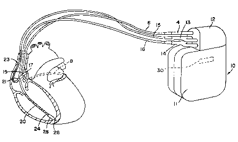
Figure 1 illustrates a defibrillator and lead set of a type in which the
present
invention may usefully be practiced. The ventricular lead includes an
elongated
insulative lead body 16, carrying three mutually insulated conductors. Located
adjacent the distal end of the lead are a ring electrode 24, an extendable
helix
electrode 26, mounted retractably within an insulative electrode head 28, and
an
elongated coil electrode 20. Each of the electrodes is coupled to one of the
conductors
within the lead body 16. Electrodes 24 and 26 are employed for cardiac pacing
and
for sensing ventricular depolarizations. At the proximal end of the lead is a
bifurcated
connector 14 that carries three electrical connectors, each coupled to one of
the coiled
conductors. The atrial/SVC lead includes an elongated insulative lead body 15,
also
carrying three mutually insulated conductors. Located adjacent the J-shaped
distal
end of the lead are a ring electrode 21 and an extendible helix electrode 17,
mounted
retractably within an insulative electrode head 19. Each of the electrodes is
coupled to
one of the conductors within the lead body 15. Electrodes 17 and 21 are
employed for
atrial pacing and for sensing atrial depolarizations. An elongated coil
electrode 23 is
provided, proximal to electrode 21 and coupled to the third conductor within
the lead
body 15. At the proximal end of the lead is a bifurcated connector 13 that
carries
three electrical connectors, each coupled to one of the coiled conductors.
The coronary sinus lead includes an elongated insulative lead body 6, carrying
one conductor, coupled to an elongated coiled defibrillation electrode 8.
Electrode 8,
illustrated in broken outline, is located within the coronary sinus and great
vein of the
WO 02/40096 CA 02429237 2003-05-16
PCT/US00/32966
7
heart. At the proximal end of the lead is a connector plug 4, which carries an
electrical connector, coupled to the coiled conductor.
The pacemaker/cardioverter/defibrillator 10 includes a hermetic enclosure 11
containing the electronic circuitry used for generating cardiac pacing pulses
for
delivering cardioversion and defibrillation shocks and for monitoring the
patient's
heart rhythm. Pacemaker/cardioverter/defibrillator 10 is shown with the lead
connector assemblies 4, 13 and 14 inserted into the connector block 12, which
serves
as a receptacle and electrical connector for receiving the connectors, 4, 13
and 14 and
interconnecting the leads to the circuitry within enclosure 11. An.activity
sensor 30 is
illustrated schematically by broken outline, and may be an accelerometer or a
piezoelectric transducer. Sensor 30 may be used for verifying that the patient
is at rest,
in conjunction with measurement of long-term heart rate and/or breathing
trends
according to the present invention as well as for regulation of pacing rate
based upon
demand for cardiac output.
Optionally, insulation of the outward facing portion of the housing 11 of the
pacemaker/cardioverter/defibrillator 10 may be provided or the outward facing
portion
may instead be left uninsulated, or some other division between insulated and
uninsulated portions may be employed. The uninsulated portion of the housing
11
optionally serves as a subcutaneous defibrillation electrode, used to
defibrillate either
the atria or ventricles. Other lead configurations and electrode locations may
of
course be substituted for the lead set illustrated. For example, atrial
defibrillation and
sensing electrodes might be added to either the coronary sinus lead or the
right
ventricular lead instead of being located on a separate atrial lead, allowing
for a two-
lead system.Figure 2 illustrates an Implantable Medical Device (IMD) of a type
appropriate for use in practicing the present invention in conjunction with
its
associated lead system, illustrated in relation to a patient's heart. The ]MD
120
includes a hermetic enclosure 124 that may contain electronic circuitry used
for
generating cardiac pacing pulses and/or for monitoring the patient's heart
rhythm. An
activity sensor 126 is illustrated schematically by broken outline, and may be
an
accelerometer or a piezoelectric transducer as discussed above in conjunction
with
CA 02429237 2011-10-28
66742-803
8
Figure 1. Mounted to the enclosure 124 is a header 122 which serves as a
receptacle
and electrical connector for receiving the connectors 132 and 134 of leads 128
and
130 and interconnecting the leads to the circuitry within enclosure 124.
In one embodiment, IMD 120 is a hemodynamic monitor of the type described
in commonly-assigned U.S. Patent Number 5,535,752 to Halperin.
In that embodiment, lead 128 includes a physiologic
sensor 144 which may take the form of an oxygen sensor, pressure sensor,
temperature sensor, other sensor of any of the various types employed for
monitoring
demand for cardiac output or for measuring heart hemodynamics. Sensor 124 may
be
used in conjunction with or as an alternative to the activity sensor 126 for
verifying
that the patient is at rest, in conjunction with measurement of long-term
heart rate
trends according to the present invention.
In another embodiment, IMD 120 is a pacing device including atrial lead 130
carrying electrodes 136 and 138. In this embodiment, the electrodes may be
employed for sensing and pacing the patient's atrium. Additionally, lead 128
is a
ventricular lead provided with electrodes 140 and 142 for monitoring and
pacing right
ventricular heart signals.
Figure 3 illustrates a subcutaneously implantable monitor of a type
appropriate
for use in practicing the present invention. The monitor shares the external
configuration of the Medtronic Reveal implantable monitor, and is provided
with a
hermetically sealed enclosure 104 containing the electronic circuitry used for
generating cardiac pacing pulses and for monitoring the patient's heart rhythm
and
which carries a molded plastic header 108. The enclosure 104 and the header
108
each carry an electrode 102 and 106, respectively for monitoring heart rhythm.
Also
mounted in the header 108 is an antenna 110 for use in communicating between
the
device and an external programmer. Illustrated in broken outline at 112 is an
internal
activity sensor, of the type typically employed in the context of rate
responsive
cardiac pacemakers, taking the form either of an accelerometer or a piezo-
electric
transducer. Heart signals are detected between the electrodes 102 and 106 and
measurements of physical activity are detected by sensor 112 for use in
storing and
WO 02/40096 CA 02429237 2003-05-16 PCT/US00/32966
9
calculating heart rate trends and heart rate variability measurements
according to the
present invention.
Figure 4 is a plan view of an external programmer of a sort appropriate for
use
in conjunction with the practice of the present invention in conjunction with
any of
the devices of Figures 1 - 3. The programmer 420 is a microprocessor
controlled
device which is provided with a programming head 422 for communicating with an
implanted device, a set of surface electrogram electrodes 459 for monitoring a
patient's electrogram, a display 455 which is preferably a touch sensitive
display,
control buttons or keys 465, and a stylist 456 for use in conjunction with the
touch
sensitive screen 455. By means of the control keys 465 and the touch sensitive
screen
455 and stylus 456, the physician may format commands for transmission to the
implantable device. By means of the screen 455, the physician may observe
information telemetered from the implantable device. The programmer is further
provided with a printer 463 which allows for hard copy records of displays of
signals
received from the implanted device such as electrograms, stored parameters,
programmed parameters and information as to heart rate trends according to the
present invention. While not visible in this view, the device may also be
provided
with a floppy disk or CD ROM drive and/or a port for insertion of expansion
cards
= such as P-ROM cartridges, to allow for software upgrades and modifications
to the
programmer 420.
In the context of the present invention, programmer 420 may serve simply as a
display device, displaying information with regard to heart rate variability
and heart
rate trends as calculated by the implanted device or instead may receive
uplinked raw
data related to heart intervals and may calculate the heart rate trends and
heart rate
variability values according to the present invention. It is believed that it
is preferable
for the implanted device to perform the bulk of the computations necessary to
practice
the invention, and in particular that it is preferable for the implanted
device to at least
calculate average rate values, to reduce the storage requirements within the
implanted
device. However, allocation of functions between the implanted device and the
programmer may differ from the preferred embodiments and still result in a
workable
system.
CA 02429237 2003-05-16
WO 02/40096 PCT/US00/32966
10
Figure 5 is a functional schematic diagram of an implantable
pacemaker/cardioverter/defibrillator of the type illustrated in Figure 3, in
which the
present invention may usefully be practiced. This diagram should be taken as
exemplary of one type of anti-tachyarrhythmia device in which the invention
may be
embodied, and not as limiting, as it is believed that the invention may
usefully be
practiced in a wide variety of device implementations, including devices
providing
therapies for treating atrial arrhythmias instead of or in addition to
ventricular
arrhythmias, cardioverters and defibrillators which do not provide anti-
tachycardia
pacing therapies, anti-tachycardia pacers which do not provide cardioversion
or
defibrillation, and devices which deliver different forms of anti-arrhythmia
therapies
such nerve stimulation or drug administration.
The device is provided with a lead system including electrodes, which may be
as illustrated in Figure 1. Alternate lead systems may of course be
substituted. If the
electrode configuration of Figure I is employed, the correspondence to the
illustrated
electrodes is as follows. Electrode 311 corresponds to electrode 11, and is
the
uninsulated portion of the housing of the implantable pacemaker/cardioverter
/defibrillator. Electrode 320 corresponds to electrode 20 and is a
defibrillation
electrode located in the right ventricle. Electrode 310 corresponds to
electrode 8 and
is a defibrillation electrode located in the coronary sinus. Electrode 318
corresponds
to electrode 28 and is a defibrillation electrode located in the superior vena
cava.
Electrodes 324 and 326 correspond to electrodes 24 and 26, and are used for
sensing
and pacing in the ventricle. Electrodes 317 and 321 correspond to electrodes
19 and
21 and are used for pacing and sensing in the atrium.
Electrodes 310, 311, 318 and 320 are coupled to high voltage output circuit
234. Electrodes 324 and 326 are coupled to the R-wave amplifier 200, which
preferably takes the form of an automatic gain controlled amplifier providing
an
adjustable sensing threshold as a function of the measured R-wave amplitude. A
signal is generated on R-out line 202 whenever the signal sensed between
electrodes
324 and 326 exceeds the present sensing threshold.
Electrodes 317 and 321 are coupled to the P-wave amplifier 204, which
preferably also takes the form of an automatic gain controlled amplifier
providing an
CA 02429237 2011-10-28
66742-803
11
adjustable sensing threshold as a function of the measured R-wave amplitude. A
signal is generated on P-out line 206 whenever the signal sensed between
electrodes
317 and 321 exceeds the present sensing threshold. The general operation of
the It-
wave and P-wave amplifiers 200 and 204 may correspond to that disclosed in
U.S.
Patent No. 5,117,824, by Keimel, et al., issued June 2, 1992, for an Apparatus
for
Monitoring Electrical Physiologic Signals.
However, any of the numerous prior art sense amplifiers employed in
implantable cardiac pacemakers, defibrillators and monitors may also usefully
be
employed in conjunction with the present invention.
Switch matrix 208 is used to select which of the available electrodes are
coupled to wide band amplifier 210 for use in digital signal analysis.
Selection of
electrodes is controlled by the microprocessor 224 via data/address bus 218,
which
selections may be varied as desired. Signals from the electrodes selected for
coupling
to bandpass amplifier 210 are provided to multiplexer 220, and thereafter
converted to
multi-bit digital signals by A/D converter 222, for storage in random access
memory
226 under control of direct memory access circuit 228. Microprocessor 224 may
employ digital signal analysis techniques to characterize the digitized
signals stored in
random access memory 226 to recognize and classify the patient's heart rhythm
employing any of the numerous signal-processing methodologies known to the
art.
Telemetry circuit 330 receives downlink telemetry from and sends uplink
telemetry to the patient activator by means of antenna 332. Data to be
uplinked to the
activator and control signals for the telemetry circuit are provided by
microprocessor
224 via address/data bus 218. Received telemetry is provided to microprocessor
224
via multiplexer 220. The atrial and ventricular sense amp circuits 200,204
produce
atrial and ventricular EGM signals, which also may be digitized, and uplink
telemetered to an associated programmer on receipt of a suitable interrogation
command. The device may also be capable of generating so-called marker codes
indicative of different cardiac events that it detects. A pacemaker with
marker-
channel capability is described, for example, in U.S. Patent No. 4,374,382 to
Markowitz.
The particular telemetry system employed is not critical to practicing the
invention,
CA 02429237 2011-10-28
66742-803
12
and any of the numerous types of telemetry systems known for use in
implantable
devices may be used. In particular, the telemetry systems as disclosed in U.S.
Patent
No. 5,292,343 issued to Blanchette et al., U.S. Patent No. 5,314,450, issued
to
Thompson, U.S. Patent No. 5,354,319, issued to Wybomy et al. U.S. Patent No.
5,383,909, issued to Keimel, U.S. Patent No. 5,168,871, issued to Grevious,
U.S.
Patent No. 5,107,833 issued to Barsness or U.S. Patent No. 5,324,315, issued
to
Grevious, are suitable for use in
conjunction with the present invention. However, the telemetry systems
disclosed in
the various other patents cited herein which are directed to programmable
implanted
devices, or similar systems may also be substituted. The telemetry circuit 330
is of
course also employed for communication to and from an external programmer, as
is
conventional in implantable anti-arrhythmia devices.
The device of Figure 5 may additionally be provided with an activity sensor
344, mounted to the interior surface of the device housing or to the hybrid
circuit
within the device housing. The sensor 344 and sensor present in circuitry 342
may be
employed in the conventional fashion described in U.S. Patent 4,428,378 issued
to
Anderson et al, regulate the
underlying pacing rate of the device in rate responsive pacing modes and also
serves
as in an indicator of the patient's activity level for use in conjunction with
the
measurement of heart rate at rest or during sleep, as discussed above and as
discussed
in more detail below in conjunction with Figures 10 and 12. In addition, the
sensor
344 may be employed to track the functional status of the patient as in the
above-cited
application by Stone et al. In such case, the device may also store trend
information
with regard to the number of and/or durations of periods in which the
patient's
physical activity meets or exceeds a defined level. Comparisons of the stored
trend of
day and/or night heart rate with trend information related to sensor output
may be
especially valuable.
The remainder of the circuitry is dedicated to the provision of cardiac
pacing,
cardioversion and defibrillation therapies, and, for purposes of the present
invention
may correspond to circuitry known in the prior art. An exemplary apparatus is
disclosed for accomplishing pacing, cardioversion and defibrillation functions
as
WO 02/40096 CA 02429237 2003-05-16PCT/US00/32966
13
follows. The pacer timing/control circuitry 212 includes programmable digital
counters which control the basic time intervals associated with DDD, VVI, DVI,
VDD, AAI, DDI, DDDR, VVIR, DVIR, VDDR, AAIR, DDIR and other modes of
single and dual chamber pacing well known to the art. Circuitry 212 also
controls
escape intervals associated with anti-tachyarrhythmia pacing in both the
atrium and =
the ventricle, employing, any anti-tachyarrhythmia pacing therapies known to
the art.
Intervals defined by pacing circuitry 212 include atrial and ventricular
pacing
escape intervals, the refractory periods during which sensed P-waves and R-
waves are
ineffective to restart timing of the escape intervals and the pulse widths of
the pacing
pulses. The durations of these intervals are determined by microprocessor 224,
in
response to stored data in memory 226 and are communicated to the pacing
circuitry
212 via address/data bus 218. Pacer circuitry 212 also determines the
amplitude of
the cardiac pacing pulses under control of microprocessor 224.
During pacing, the escape interval counters within pacer timing/control
circuitry 212 are reset upon sensing of R-waves and P-waves as indicated by
signals
on lines 202 and 206, and in accordance with the selected mode of pacing on
time-out
trigger generation of pacing pulses by pacer output circuits 214 and 216,
which are
coupled to electrodes 317, 321, 324 and 326. The escape interval counters are
also
reset on generation of pacing pulses, and thereby control the basic timing of
cardiac
pacing functions, including anti-tachyarrhythmia pacing.
The durations of the intervals defined by the escape interval timers are
determined by microprocessor 224, via data/address bus 218. The value of the
count
present in the escape interval counters when reset by sensed R-waves and P-
waves
may be used to measure the durations of R-R intervals, P-P intervals, PR
intervals and
R-P intervals, which measurements are stored in memory 226 and are used in
conjunction with the present invention to measure heart rate variability and
heart rate
trends and in conjunction with tachyarrhythmia detection functions.
Microprocessor 224 operates as an interrupt driven device, and is responsive
to
interrupts from pacer timing/control circuitry 212 corresponding to the
occurrences of
sensed P-waves and R-waves and corresponding to the generation of cardiac
pacing
pulses. These interrupts are provided via data/address bus 218. Any necessary
CA 02429237 2011-10-28
66742-803
14
mathematical calculations to be performed by microprocessor 224 and any
updating
of the values or intervals controlled by pacer timing/control circuitry 212
take place
following such interrupts. Microprocessor 224 includes associated ROM in which
the
, stored program controlling its operation as described below resides. A
portion of the
memory 226 (Figure 2) may be configured as a plurality of recirculating
buffers,
capable of holding series of measured intervals, which may be analyzed in
response to
the occurrence of a pace or sense interrupt to determine whether the patient's
heart is
presently exhibiting atrial or ventricular tachyarrhythmia.
The arrhythmia detection method of the present invention may include any of
the numerous available prior art tachyarrhythmia detection algorithms. One
preferred
embodiment may employ all or a subset of the rule-based detection methods
described
in U.S. Patent No. 5,545,186 issued to Olson et al. or in U.S. Patent No.
5,755,736
issued to Gillberg et al.
However, any of the various other arrhythmia detection methodologies known to
the
art might also be employed.
In the event that an atrial or ventricular tachyarrhythmia is detected, and an
anti-tachyarrhythmia pacing regimen is desired, timing intervals for
controlling
generation of anti-tachyarrhythmia pacing therapies are loaded from
microprocessor
224 into the pacer timing and control circuitry 212, to control the operation
of the
escape interval counters therein and to define refractory periods during which
detection of R-waves and P-waves is ineffective to restart the escape interval
counters.
In the event that generation of a cardioversion or defibrillation pulse is
required, microprocessor 224 employs the escape interval counter to control
timing of
such cardioversion and defibrillation pulses, as well as associated refractory
periods.
In response to the detection of atrial or ventricular fibrillation or
tachyarrhythmia
requiring a cardioversion pulse, microprocessor 224 activates
cardioversion/defibrillation control circuitry 230, which initiates charging
of the high
voltage capacitors 246, 248 via charging circuit 236, under control of high
voltage
charging control line 240. The voltage on the high voltage capacitors is
monitored via
VCAP line 244, which is passed through multiplexer 220 and in response to
reaching
a predetermined value set by microprocessor 224, results in generation of a
logic
CA 02429237 2003-05-16
WO 02/40096 PCT/US00/32966
15
signal on Cap Full (CF) line 254, terminating charging. Thereafter, timing of
the
delivery of the defibrillation or cardioversion pulse is controlled by pacer
timing/control circuitry 212. Following delivery of the fibrillation or
tachycardia
therapy the microprocessor then returns the device to cardiac pacing and
awaits the
next successive interrupt due to pacing or the occurrence of a sensed atrial
or
ventricular depolarization. In the illustrated device, delivery of the
cardioversion or
defibrillation pulses is accomplished by output circuit 234, under control of
control
circuitry 230 via control bus 238. Output circuit 234 determines whether a
monophasic or biphasic pulse is delivered, whether the housing 311 serves as
cathode
or anode and which electrodes are involved in delivery of the pulse.
Figure 6 is a functional schematic diagram of the pacemaker 120 illustrated in
Figure 2. The pacemaker of Figures .2 and 6 is essentially a set of
subcomponents of
the implantable pacemaker/cardioverter/defibrillator illustrated in Figures 1
and 5.
Like the device of Figure 5, the pacemaker is a microprocessor-controlled
device with
microprocessor 189 operating under control of programming stored in Read Only
Memory (ROM) 191. In the device as illustrated, electrodes 136 and 138,
intended
for location in the atrium of the patient's heart are coupled to an atrial
amplifier 181
which may correspond to atrial amplifier 204 in Figure 5. Similarly,
ventricular
electrodes 140 and 142 are coupled to ventricular amplifier 182, which may
correspond to ventricular amplifier 200 in Figure 5. The outputs of atrial and
ventricular amplifiers 181 and 182 are input into timing and control circuitry
183
which conforms generally to the pacer timing and control circuitry 212 of
Figure 5,
and which measures intervals between detected depolarizations and controls
intervals
between delivered pacing pulses as well as generating interrupts via
data/address 192
to awake microprocessor 189 in response to delivery of a pacing pulse or
sensing of a
cardiac depolarization. Intervals between depolarizations measured by
timing/control
circuitry 183 are stored in Random Access Memory (RAM) 190 until processed by
microprocessor 189 to derive average heart rate values. Atrial and ventricular
pacing
pulses delivered according to one or more of the standard pacing modes
described in
conjunction with Figure 5 are produced by atrial and ventricular pulse
generator
CA 02429237 2011-10-28
66742-803
16
circuits 184 and 185 which may correspond to pulse generator circuits 215 ad
216 in
Figure 5.
The sensor illustrated in Figure 6 may correspond to either an activity sensor
126 as described in conjunction with Figure 2 above, to a hemodynamic sensor
140,
as described in conjunction with one embodiment of Figure 2, or to a
respiration
sensor. If the sensor is an activity sensor, then sensor-processing circuitry
186 may
correspond to sensor processing circuitry 342 discussed in conjunction with
Figure 5.
However, if the sensor is a hemodynamic sensor, the sensor processing
circuitry
would correspond to the sort of processing circuitry typically associated with
hemodynamic sensors. For purposes of the present invention, the hemodynamic
sensor may be, for example, an oxygen saturation sensor in conjunction with
associated processing circuitry as described in U.S. Patent No. 6,125,290
issued to
Miesel, a pressure sensor and associated sensor processing circuitry as
described in
U.S. Patent No. 6,024,704 issued to Meador et al., an impedance sensor and
associated sensor processing circuitry as described in U.S. Patent No.
5,876,353
issued to Riff, or a temperature sensor and associated processing circuitry as
described
in U.S. Patent No. 5,957,961 issued to Maguire et al., ;
or may correspond to other types of physiologic sensors,
as may be appropriate. As discussed in more detail below, in the context of
the
present invention, the sensor 126, 140 is employed to determine when the
patient is in
a resting state, for purposes of controlling the gathering and storage of
information
related to long term heart rate trends. Telemetry circuitry 187 in conjunction
with
antenna 188 serves to transmit information to and receive information from an
external programmer precisely as described above in conjunction with the
device of
Figure 5, including information related to stored median interval values and
heart rate
variability measurements in RAM 190, as calculated by microprocessor 189.
Figure 7 illustrates the functional organization of the subcutaneously
implantable heart monitor 100 illustrated in Figure 3. This device consists
essentially
of a set of subcomponents of the more complex embodiment of the invention
disclosed in Figure 5, and includes a sense amplifier 152 coupled to
electrodes 102
and 106, illustrated in Figure 1. Sense amplifier 152 may correspond to sense
WO 02/40096 CA 02429237 2003-05-16 PCT/US00/32966
17
amplifier 204 or 200 in Figure 5. Like the device of Figure 5, the implantable
monitor
may be a microprocessor control device operating under control microprocessor
156
with its functionality controlled primarily by software stored in the read
only memory
associated therein. In this context, amplifier 152 detects the occurrence of
heart
depolarizations, with timing/control circuitry 154 serving to measure the
durations
between the detected heart depolarizafions and to generate interrupts
awakening
microprocessor 156 so that it may store, analyze and process the detected
intervals.
Random Access Memory (RAM) 158 serves to store measured and calculated
parameters including the calculated average heart rate values for later
telemetry to an
external device. Like the device in Figure 5, timing and control circuitry
communicates with the microprocessor and the remaining circuitry by means of
the
address/data bus 168. Telemetry system 162 may correspond to telemetry system
330
in Figure 5 and, via antenna 110 transmits and receives information from the
external
programmer, including transmitting information with regard to the calculated
median
rate values and heart variability values stored in RAM 158. Sensor 112 may
correspond to sensor 344 in Figure 5 and it may be a physical activity sensor
as
discussed above. The output of sensor 112 is passed through sensor processing
circuitry 166 which may correspond to sensor processing circuitry 342 in
Figure 5.
Figure 8 is a functional schematic of a programmer as illustrated in Figure 4
appropriate for use in conjunction with the invention. Programmer 420 is a
personal
computer type, microprocessor-based device incorporating a central processing
unit
450, which may be, for example, an Intel 80386 or 80486 or Pentium
microprocessor
or the like. A system bus 451 interconnects CPU 450 with a hard disk drive 452
storing operational programs and data and with a graphics circuit 453 and an
interface
controller module 454. A floppy disk drive 466 or a CD ROM drive is also
coupled
to bus 451 and is accessible via a disk insertion slot within the housing of
the
programmer 420. Programmer 420 further comprises an interface module 457,
which
includes digital circuit 458, non-isolated analog circuit 459, and isolated
analog circuit
460. Digital circuit 448 enables interface module 457 to communicate with
interface
controller module 454.
CA 02429237 2003-05-16
WO 02/40096 PCT/US00/32966
18
In order for the physician or other caregiver or user to communicate with the
=
programmer 420, control buttons 465 or optionally a keyboard coupled to CPU 50
are
provided. However the primary communication mode is through graphics display
screen 455 of the well-known "touch sensitive" type controlled by graphics
circuit
453. A user of programmer 420 may interact therewith through the use of a
stylus
456, also coupled to graphics circuit 453, which is used to point to various
locations
on screen 455, which display menu choices for selection by the user or an
alphanumeric keyboard for entering text or numbers and other symbols.
Graphics display 455 also displays a variety of screens of telemetered out
data
or real time data including measurements of heart rate variability and heart
rate trends
according to the present invention. Programmer 420 is also provided with a
strip
chart printer 463 or the like coupled to interface controller module 454 so
that a hard
copy of a patient's ECG, EGM, marker channel or of graphics displayed on the
display
455 can be generated.
As will be appreciated by those of ordinary skill in the art, it is often
desirable
to provide a means for programmer 20 to adapt its mode of operation depending
upon
the type or generation of implanted medical device to be programmed.
Accordingly,
it may be desirable to have an expansion cartridge containing EPROM's or the
like for
storing software programs to control programmer 420 to operate in a particular
manner corresponding to a given type or generation of implantable medical
device. In
addition, in accordance with the present invention, it is desirable to provide
the
capability through the expansion cartridge or through the floppy disk drive 66
or CD
ROM drive.
The non-isolated analog circuit 459 of interface module 457 is coupled to a
programming head 422, which is used to establish the uplink and downlink
telemetry
links between the pacemaker 410 and programmer 420 as described above. Uplink
telemetered EGM signals are received in programming head 422 and provided to
non-
isolated analog circuit 459. Non-isolated analog circuit 459, in turn,
converts the
digitized EGM signals to analog EGM signals and presents these signals on
output
lines A EGM OUT and V EGM OUT. These output lines may then be applied to a
strip-chart recorder 463 to provide a hard-copy printout of the A EGM or V EGM
for
WO 02/40096 CA 02429237 2003-05-16 PCT/US00/32966
19
viewing by the physician. Similarly, the markers received by programming head
422
are presented on the MARKER CHANNEL output line from non-isolated analog
circuit 459.
Isolated analog circuit 460 in interface module 547 is provided to receive
external ECG and electrophysiologic (EP) stimulation pulse signals. In
particular,
analog circuit 460 receives ECG signals from patient skin electrodes 459 and
processes these signals before providing them to the remainder of the
programmer
system in a manner well known in the art. Circuit 460 further operates to
receive the
EP stimulation pulses from an external EP stimulator for the purposes of non-
invasive
EP studies, as is also known in the art.
In order to ensure proper positioning of programming head 422 over the
antenna of the associated implanted device, feedback is provided to the
physician that
the programming head 422 is in satisfactory communication with and is
receiving
sufficiently strong RF signals. This feedback may be provided, for example, by
means of a head position indicator, e.g. a light-emitting diode (LED) or the
like that is
lighted to indicate a stable telemetry channel.
Figure 9 illustrates a functional flow chart describing a first method of
calculating average heart rates during predetermined time periods within the
course of
a day. For example, day-time and night-time heart rate averages may be
calculated
for use in determining heart rate trends that may then be displayed on an
associated
external programmer. In this context, the flow chart of Figure 9 starts from
the
assumption that the implanted device will collect the measured heart intervals
and
calculate and store the average heart interval values for day heart rate
and/or night
heart rate, with the calculated average day heart rate and night simply
displayed on the
external device associated with the implanted device. In this context, it
should also be
understood that all calculations and processing of the measured heart
intervals is
performed by the microprocessor within the implanted device. However, as noted
above, alternate divisions of tasks between the implanted and external devices
are still
believed to be within the scope of the invention.
At 600, the device is initialized and thereafter sets SUMNN = 0 at 602.
SUMNN is a running sum of the total duration of measured heart intervals
retained for
WO 02/40096 CA 02429237 2003-05-16 PCT/US00/32966
20
use in calculation of average heart rate according to the present invention.
The device
also sets the value of NN = 0 in 602. NN is the running total of measured
heart
intervals employed in calculation of average day or night heart rates
according to the
present invention. The device then waits until the time of day falls within
the desired
time window extending from a start time "A" to an end time "B" at 604. In the
context of monitoring of average daily heart rate, the defined time range may
extend
between 8:00 a.m. and 8:00 p.m., for example. In the context of a device which
measures average nightly heart rate, the defined range may extend between
12:00 a.m.
and 4:00 a.m., for example. It should be also understood that the same device
may
make and store measurements of both average day heart rate and average night
heart
rate.
If the device determines that present time T is within the defined desired
time
range for heart range monitoring, in response to a sensed or paced
depolarization at
606, the device at 608 stores the measured heart interval separating the
sensed or
paced depolarization 606 from the preceding paced or sensed depolarization, as
measured in milliseconds. In one embodiment, all intervals within the desired
time
range are retained for purposes of calculating an average rate. In another
embodiment, only intervals terminating in a sensed depolarization are
retained. That
is, in this alternative embodiment, only "sense-to-sense" intervals and "pace-
to-sense"
intervals are measured, with "sense-to-pace" and "pace-to-pace" intervals
being
discarded as not being indicative of a natural heart rate. Of course, if the
invention is
implemented within a hemodynamic monitoring device that does not provide
pacing
therapy, all intervals will be retained in both embodiments.
At 610, the device determines whether the measured heart interval is
acceptable for use in determining average heart rate or should be rejected.
The
desirability of rejecting measured heart intervals will depend upon the
condition of the
patient and the type of device implanted. For example, in the case of a
patient who is
subject to atrial or ventricular tachycardia, wherein the device employing the
present
invention is an implantable pacemaker/cardioverteridefibrillator, it may be
desirable
to discard all measured heart intervals associated with detection and
treatment of
tachyarrhythmias. For example the device may reject all intervals which meet
WO 02/40096 CA 02429237 2003-05-16PCT/US00/32966
21
tachyarrhythmia detection criteria due to their relatively short duration, all
intervals
obtained during charging of the output capacitors of such a device prior to
delivery of
a cardioversion or defibrillation shock and all intervals sensed during
delivery of anti-
tachyarrhythmia therapies such as anti-tachycardia pacing, cardioversion and
defibrillation. In contrast, if the invention is embodied in a simple VVI-type
pacemaker, and the patient is not subject to tachyarrhythmias, there may be no
need to
discard any heart intervals ending on a sensed depolarization. In addition or
as an
alternative, in which the invention is embodied to include a dual chamber
pacemaker
capable of switching between various pacing modes in response to detected
atrial
tachyarrhythmias, it may be desirable to discard heart intervals measured
during
operation of the mode switch between pacing modes.
If the measured heart interval is not rejected, the value of the interval is
added
to SUMNN at 612, and the value of NN is incremented by one at 614. The device
continues to increment the values of SUMNN and NN according to this mechanism
until the present time T equals or exceeds the defined expiration time B for
heart rate
monitoring. At 616, the device compares the total duration of measured and
saved
intervals to a desired total duration "X" which may reflect a predetermined
proportion
of the duration of the monitoring interval. For example, the value of SUMNN
may
have to exceed 20% of the defined monitoring period. In the event that the
value of
SUMNN is inadequate, the device stores an indication that no heart rate has
been
calculated for the monitoring period presently in effect at 620, and the
device resets
the values of SUMNN and NN to zero at 602, awaiting the next defined
monitoring
interval. If the value of SUMNN is adequate, the average heart rate HR in
beats per
minute is calculated by means of the equation HR 60,000/(SUMNN/NN) at 622,
and the value of HR, representing the average heart rate over the monitoring
period is
stored at 624 for later telemetry to the associated external device and for
display by
the associated external device. The method of operation illustrated in Figure
9 may be
employed to collect and calculate average daily rates, average night heart
rates, or
both, for display on the associated external device.
Figure 10 illustrates an alternative embodiment of the present invention in
which an associated activity sensor or other metabolic sensor is employed in
order to
CA 02429237 2003-05-16
WO 02/40096 PCT/US00/32966
22
assure that during the defined heart rate monitoring periods, only heart
intervals
indicative of the patient at rest are employed in calculating average heart
rates. It
should be noted that the method of operation illustrated in Figure 10 also
permits the
calculation of average resting heart rates over 24 hour periods, by simply
designating
the desired monitoring period as successive 24 hour periods rather than
discreet
periods within each 24 hour period.
After initialization at 700, the device sets SUMNN and NN to zero at 702, as
discussed above in conjunction with Figure 9, and awaits the beginning of the
defined
monitoring period at 704. At 706, the device initiates the relatively shorter
time
period Ti, over which the patient's physical activity or other metabolic
indicator of
demand for cardiac output is to be monitored. The values of INTCOUNT,
indicative
of the number of intervals counted during this shorter time interval Ti and
INTSUM,
reflective of the total duration of intervals stored during interval Ti.are
reset to zero at
706. The value of Ti is preferably fairly short, for example, in the range of
a few
minutes, for example, about two to five minutes. Thereafter, until expiration
of the
shorter period Ti at 712, each time a paced or sensed depolarization is occurs
at 708,
the heart interval separating the depolarization from the preceding
depolarization is
stored at 710, and the device determines whether the stored interval should be
rejected
at 726, in a fashion analogous to that described in conjunction with Figures 9
above.
If the interval is saved, the value of INTCOLINT is incremented by one at 728
and the
value of INTSUM is incremented by the duration of the stored heart interval at
730.
This process continues until expiration of time period Ti at 712. Following
expiration of Ti at 712, the device checks the output of the sensor over the
preceding
time period Ti and compares the output to a defined threshold to determine
whether
the patient is at rest at 714. For example, if the sensor output takes the
form of
successive numerical values (e.g. counts) generated over Ti, the sum, mean, or
median of the numerical values generated during TI may be calculated and
analyzed,
for example by comparison to a threshold value, to determine whether the
patient was
at rest during Ti. If the sensor's output based on directly measured activity
or other
measured metabolic demand indicator indicates the patient was not at rest, the
intervals collected during the preceding shorter Ti period are discarded, and
the next
CA 02429237 2003-05-16
WO 02/40096 PCT/US00/32966
23
Ti period is initiated at 706. If the activity sensor or other indicator of
metabolic
demand indicates that the patient was at rest during the preceding shorter
time period
Ti, the value of NN is incremented by the value of INTCOLTNT at 732 and the
value
of SUMNN is incremented by INTSUM at 734. This process continues until the
device determines at 736 that the present time T is equal to or after the
expiration
point B of the defined monitoring period.
On expiration of the defined monitoring period, the device checks at 724 to
determine whether the value of SUMNN exceeds a desired total duration,
precisely as
described above, in conjunction with Figure 9. If the total duration of stored
heart
intervals is less than the desired total, the device stores an indication that
no
measurement of average heart rate was stored for the monitoring period at 720.
However, if the total duration of measured heart intervals is sufficiently
great, the
value of the average heart rate is calculated at 718 in the same fashion as
discussed in
conjunction with Figure 10 above, and the stored value of the average heart
rate for
the monitoring interval is stored at 716 for later telemetry to an associated
external
device for display thereon.
It may be noted that the time interval Ti may be selected as one or more hours
long. Alternatively, Ti may be less than one hour long. If desired, Ti may be
reduced to a value that approximates one heart interval so that the activity
level of the
patient is tracked on a beat-to-beat basis.
Figure 11 illustrates a functional flow chart describing an alternative
embodiment of the present invention in which sensor outputs are monitored over
daytime or nighttime periods, in a manner analogous to the collection of heart
rate
information as discussed in conjunction with Figure 9 and 10 above. The term
"average" in the context of Figure 11 is the same as discussed above in
conjunction
with monitoring of heart rates. The sensor may be an activity sensor as
described
above or any of the various known physiologic sensors available for implant in
the
human body, including but not limited to sensors of metabolic demand for
oxygenated
blood, including oxygen saturation sensors, blood pressure sensors, blood
temperature
sensors, Ph sensors, Respiration sensors and the like.
CA 02429237 2003-05-16
WO 02/40096 PCT/US00/32966
24
Calculation of a daily sensor output and a night sensor output value may be
used, for example, in constructing day sensor output trends and night sensor
output
trends for display on the associated external programmer. In this context, the
flow
chart of Figure 11 starts from the assumption that the implanted device will
collect the
measured sensor output values and calculate and store average or total values
for day
sensor output and/or night sensor output, with the calculated average or total
value
displayed on the external device associated with the implanted device. In this
context,
it should also be understood that all calculations and processing of the
measured
sensor output values are performed by the microprocessor within the implanted
device. However, as noted above, alternate divisions of tasks between the
implanted
and external devices are still believed to be within the scope of the
invention.
At 800, the device is initialized and thereafter sets SUMSENS = 0 at 602.
SUMSENS is a running sum of the total of measured sensor outputs retained for
use
in calculation of average or total sensor output according to the present
invention.
The device then waits until the time of day falls within the desired time
window
extending from a start time "A" to an end time "B". In the context of
monitoring of
daily sensor output, the defined time range may extend between 8:00 a.m. and
8:00
p.m., for example. In the context of a device that measures nightly sensor
output, the
defined range may extend between 12:00 a.m. and 4:00 a.m., for example. It
should
be also understood that the same device may make and store measurements of
both
day and night sensor outputs.
If the device determines that present time T is within the defined desired
time
range for heart range monitoring, in response to a new output sensor value at
806, the
device at 808 stores the measured sensor output as a numerical value. The
value of
the sensor output (SO) is added to SUMSENS at 812. The device continues to
increment the values of SUMSENS according to this mechanism until the present
time T equals or exceeds the defined expiration time B for sensor output
monitoring at
816. On expiration of the defined time for sensor output monitoring, the
device either
stores SUMSENS at 820 or optionally calculates and stores an average sensor
output
value at 822 and 824, for example calculated based on SUMSENS and the duration
of
the defined time for sensor output monitoring or based on SUMSENS and the
total
CA 02429237 2011-10-28
66742-803
25
number of sensor outputs included in SUMSENS, in a fashion analogous to that
employed to calculate heart rate averages according to the method illustrated
in Figure
9.
According to one aspect of the invention, the physiologic sensor is an
implanted impedance sensor employed to measure respiration rates, as may be
provided by an implantable medical device such as that shown in Figure 2.
Systems
using impedance sensors to measure patient respiratory trends are disclosed in
U.S.
Patent No. 5,957,861 issued Combs et al, U.S. Patent No. 5,876,353 issued to
Riff et
al, or U.S. Patent No. 5,562,711 issued to Yerich et al.
As discussed above, respiration rates are often tracked using minute
ventilation. Minute ventilation is defined as the total amount of gas that is
moved
into, and out of, the lungs in one minute. This measurement is generally
obtained in a
clinical setting using a flow meter positioned within a patient's mouth.
However, the
inventors have shown that minute ventilation can also be closely approximated
by
measuring the changes in tissue impedance that occur as the lungs expand and
contract during breathing, as may be detected by an implanted impedance
sensor.
The current invention provides a system and method for monitoring minute
ventilation in a manner that extends beyond the clinical setting so that long-
term
trends in patient health may be more accurately evaluated. For example, the
invention may be used to detect otherwise unrecognized acute disease or acute
deterioration in the status of chronic disease. Early detection of otherwise
unrecognized acute disease pennits treatment that can potentially prevent, or
minimize, further progression of the disease.
Many health conditions cause changes in minute ventilation rates. For
example, elevated minute ventilation can be caused by acute heart failure,
acute
cardiac ischemia, renal failure, pneumonia, pulmonary congestion, pulmonary
edema,
pulmonary embolism, acute asthma, fever, sepsis, shock, and stroke.
Additionally,
minute ventilation trends that include a period of increased breathing rate
followed by
a significantly slowed breathing rate may indicate Cheyne-Stokes respiration
or sleep
CA 02429237 2003-05-16
WO 02/40096 PCT/US00/32966
26
apnea. Detection of Cheyne-Stokes respiration is particularly critical since
this
symptom is present in up to forty percent of all heart failure patients.
As stated above, the current invention provides a system for monitoring long-
term trends in minute ventilation using impedance measurements. The inventors
have determined that transthoracic impedance minute ventilation measurements
have
a good correlation to minute ventilation measurements obtained using an
external gas
flow meter. It may be noted, however, that the correlation between a minute
ventilation measurement obtained using an impedance sensor and a measurement
obtained using a flow meter may vary on a patient-to-patient basis. In other
words, if
two patients manifest a change in minute ventilation value measured using the
impedance system described above, they may not exhibit an identical change in
minute ventilation values measured using a flow meter. Therefore, for purposes
of
employing average values of measured minute ventilation as a diagnostic
criterion, it
is recommended that proportional, rather than absolute, changes in minute
ventilation
values be employed for diagnostic purposes. For example, it has been found
that a
percentage changes in minute ventilation measured using the impedance-based
system
correspond very well to the percentage changes in minute ventilation as
measured by
the flow meter.
According to one aspect of the invention, displays of trend lines obtained
using an impedance sensor may be formatted using a percentage of change scale
as
opposed to an absolute value of a ventilation scale. In the context of the
present
invention it is anticipated that a programmer as described above may be used
to
display a trend line of the measured minute ventilation values, and that a
particularly
useful display might employ a baseline of average minute ventilation values
obtained
prior to the values displayed, with a vertical axis indicative of a percentage
change
from the baseline associated with each subsequent monitoring period.
Similarly,
changes in minute ventilation may be used as a means for triggering an
indicator or an
alarm, or for altering an operative parameter of the medical device so that a
clinician
may be alerted of a patient's changing condition. In this case as in the cases
discussed
above, it is suggested that the programmer or implanted device employ a
percentage
change in minute ventilation as a threshold for detection.
CA 02429237 2003-05-16
WO 02/40096 PCT/US00/32966
27
According to one aspect of the invention, minute volume measurements are
obtained only when the patient is at rest. As discussed above, this can be
determined
using an activity sensor or another sensor for measuring metabolic parameters.
Preferably, impedance measurements indicative of minute ventilation are taken
only
after the patient has been inactive for at least several minutes. Limiting
measurements
to time periods when the patient is at rest eliminates the need to evaluate
physical
exertion, which will also affect minute ventilation.
In one embodiment of the invention, minute ventilation is only measured
during predetermined time periods. For example, the time period employed to
monitor respiration during night time hours may be limited to the vicinity of
12
o'clock midnight, and more preferably to a monitoring period between about
12:00
a.m. to about 2:00 a.m. Testing by the inventors has determined that minute
ventilation measurements using impedance sensors as described in the above-
cited
patents show the greatest repeatability (least variability) over multiple
measurement
cycles when measured during this time period. As such, this particular time
period
provides the best opportunity for measuring changes in minute ventilation
characteristics as reflective of a real change in the patient's underlying
condition.
Therefore, this offers the best opportunity for updating the base line value
for use in
an impedance sensor employed to measure minute ventilation. The inventors have
also determined that in the context of a device which monitors respiration
during
daytime or evening hours, periods between approximately 12:00 p.m. to 2:00
p.m. and
approximately 6:00 p.m. to 8:00 p.m. also provide relatively high levels of
repeatability, and might also be useful for obtaining baseline values
corresponding to
minute ventilation.
During the selected monitoring periods, average minute ventilation values may
be stored according to the mechanism discussed above in conjunction with
Figure 11,
and may be employed to generate minute ventilation trend line analysis for use
by the
physician in monitoring changes in the patient's underlying physical
condition. In
addition, the average minute ventilation value obtained during a defined
monitoring
period or periods may be employed as a baseline to regulate the relationship
betweeni
WO 02/40096 CA 02429237 2003-05-16 PCT/US00/32966
28
measured minute ventilation values and pacing rate, according to the above-
discussed
Yerich patent.
Figure 12 is a functional flow chart illustrating a method of monitoring
breathing trends, which may be employed in conjunction with the present
invention.
In step 830, an Abnormal Breathing Index (ABI) is set to zero. Then it is
determined
whether the current time "T" is between a predetermined start time "A" and a
predetermined end time "B". This is shown in decision steps 832 and 834. When
time "T" is between the predetermined start and end times, which in one
embodiment
of the invention may be 12:00 a.m. to 2:00 a.m., respectively, processing
continues to
step 836. In step 836, monitoring of minute ventilation is performed by
collecting and
storing impedance sensor data. The collection of data may be further pre-
conditioned
on a measurement that confirms the patient is inactive. Such a measurement may
be
provided by a posture sensor, an activity sensor, or a sensor for measuring a
metabolic
parameter. In the event the patient is not inactive during the time period,
the
measurement is not taken until inactivity is confirmed.
In one embodiment, collected data is processed in incremental time periods I',
to determine whether abnormal breathing has occurred, as shown in step 838.
Abnormal breathing may be detected by determining that the minute ventilation
is
outside of predetermined "normal" limits for the particular time period. These
limits
may be different, for example, during night-time monitoring as compared to day-
time
monitoring when the patient is at rest. The number of breaths may also be used
in
conjunction with the volume of gas expelled as measured by minute ventilation
to
determine abnormal breathing patterns. For example, detection of greater than
twenty-five breaths per minute may be used as an indicating of an abnormal
breathing
pattern.
The incremental time period Ty, selected for use in the inventive process may
be any time period shorter than the total monitoring time (B-A), and in one
embodiment, is set to one minute. The calculation of minute ventilation over
incremental time periods is useful in detecting irregular breathing patterns
such
Cheyne-Stokes respiration, or as breathing patterns caused by sleep apnea. As
noted
above, during Cheyne-Stokes respiration or when experiencing sleep apnea, a
patient
WO 02/40096 CA 02429237 2003-05-16 PCT/US00/32966
29
may exhibit a first time period of increased minute ventilation followed by a
second
time period of significantly reduced minute ventilation. This pattern is
generally
repeated multiple times in succession. Other types of conditions discussed
above will
also cause an increase or decrease in minute ventilation over short time
periods.
If an abnormal breathing pattern is detected in decision step 840, the ABI is
incremented, as illustrated in step 842, and monitoring continues as shown by
arrow
844. Otherwise, if the breathing pattern is considered normal, monitoring
continues
as shown by arrow 846.
When the monitoring time period elapses such that current time "T" is greater
than, or equal to time "B", the calculated ABI may be stored for use in
determining
long-range trends. If desired, the calculated ABI may be used to update a
running
average ABI value, as may be desirable to conserve memory within an
Implantable
Medical Device. This is shown in step 848. Processing then continues to step
830
and the method is repeated.
Figure 13 is a flowchart illustrating the use of heart rate and respiration
trend
data as is generated by use of the current invention. As noted above, heart
rate and
minute ventilation data may be temporarily stored in a storage device such as
RAM
226 (Figure 5.) At predetermined times, this data may be retrieved from the
storage
device and transferred via a communication circuit such as telemetry circuit
330 to
external programmer 420. This is shown in step 900 of Figure 13. Once the data
is
transferred, it may be further manipulated, and displayed for user analysis,
as
illustrated in step 902. The data may also be further processed for diagnostic
purposes, as depicted by step 904. For example, minute ventilation data may be
analyzed to determine whether a patient is likely undergoing Cheyne-Stokes
respiration. If so, other patient data may be used in conjunction with this
apparent
respiration trend to determine whether the patient is experiencing the onset
of a
illness such as heart disease.
In some embodiments, patient therapy may be modified based on the
diagnosis, as indicated by step 906. For example, assuming a patient has been
provided with a bi-ventricular pacing device, bi-ventricular pacing could be
initiated,
or associated pacing parameters could be adjusted, based on the apparent
progression
WO 02/40096 CA 02429237 2003-05-16PCT/US00/32966
30
of a heart failure condition. Such parameters could be transferred to the IMD
via
programmer 420 and telemetry circuit 330 for storage in RAM 226, for instance.
Variations and modifications to the present invention may be possible given
the above disclosure. However, all such variations and modifications are
intended to
be within the scope of the invention claimed by this letters patent.
In conjunction with the above disclosure, we claim: