Note: Descriptions are shown in the official language in which they were submitted.
CA 02430034 2009-04-14
TITLE OF THE INVENTION
OVERTURNING MOMENT MEASUREMENT SYSTEM
BACKGROUND OF THE INVENTION
100031 The present invention relates to stability in industrial lifting
machines
and, more particularly, to a measurement system for a lifting vehicle for
assessing
machine stability.
[0004] As a boom is extended and a load is applied to the platform or bucket
thereof, the vehicle or lift structure's center of mass moves outwardly toward
the
supporting wheels, tracks, outriggers or other supporting elements being used.
If a
sufficient load is applied to the boom, the center of mass will move beyond
the
wheels or other supporting elements and the vehicle lift will tip over.
[0005] In the context of boom lifts, two types of stability are generally
addressed, namely "forward" and "backward" stability. "Forward" stability
refers to
that type of stability addressed when a boom is positioned in a maximally
forward
position. In most cases, this will result in the boom being substantially
horizontal.
On the other hand, "backward" stability refers to that type of stability
addressed when
a boom is positioned in a maximally backward position (at least in terms of
the lift
angle). This situation occurs when a boom is fully elevated, and the turntable
is
swung in the direction where
1
CA 02430034 2009-04-14
~
the turntable counterweight contributes to a destabilizing moment. In most
cases, this
will result in the boom being close to vertical, if not completely so.
[0006] Typically, not only can a boom be displaced (i.e., pivoted) through a
vertical plane, but also through a horizontal plane. In a boom lift, for
example,
horizontal positioning is usually effected via a turntable that supports the
boom. The
turntable, and all components propelled by it (including the boom and work
platform),
are often termed the "superstructure." As the wheeled chassis found in typical
lift
arrangements will usually not exhibit complete circumferential symmetry of
mass, it
will be appreciated that there exist certain circumferential positions of the
boom that
are more likely to lend themselves to potential instability than others. Thus,
in the
case of a lift in which the chassis or other main frame does not exhibit
symmetry of
mass with regard to all possible circumferential positions of the boom, then a
greater
potential for instability will exist, for example, along a lateral direction
of the chassis
or main frame, that is, in a direction that is orthogonal to the longitudinal
lie of the
chassis or main frame (assuming that the "longitudinal" dimension of the
chassis or
main frame is defined as being longer than the "lateral" dimension of the
chassis or
main frame). Thus, when incorporating safety requirements into the lift, these
circumferential positions of maximum potential instability must be taken into
account.
[0007] A more detailed discussion of lift machine stability can be found in
U.S. Pat. No. 6,098,823.
[0008] Stability problems can also arise due to operator improper operation or
misuse, for example, if an operator attempts to lift extra weight and exceeds
the
machine capacity. When overloaded, the loss of machine stability could lead to
the
machine tipping over. Improper operation or misuse could also arise if an
operator
gets the machine stuck in the mud, sand, or snow and proceeds to push himself
out by
telescoping the boom and pushing into the ground. This also leads, in addition
to
possible structural damage and malfunctioning of the machine, to a tipping
hazard.
Still another example of improper operation or misuse could occur if an
operator lifts
a part of the boom onto a beam or post and continues to try to lift. The
result is
similar to the overloading case.
2
CA 02430034 2003-05-26
[0009] The use of stability limiting and warning systems in load bearing
vehicles
has been practiced for several years. Most have been in the form of envelope
control.
For example, given the swing angle, boom angle, and boom length, a
conservative
envelope stability system could be developed for a telescopic boom lift or
crane. In this
method, the number of sensors necessary to achieve the stability measurement
is high and
contributes to poor reliability and increased cost, especially for machines
with
articulating booms. In addition, the load in the platform needs to be
independently
monitored.. Another practiced method is to measure boom angle and lift
cylinder
pressure. In theory, as the load increases, the pressure in the cylinder
supporting the
boom also increases. But in reality, it is more complicated. Indeed at high
angles, for
example, much of the load passes into the boom mounting pins and will not
result in an
appropriate increase in cylinder pressure. Also, hysterisis errors are
significant, where
the pressures may substantially differ for the same boom angle depending on
whether the
boom angle was reached by raising or lowering the boom.
[0010] Several other similar methods can also be found on the market. However,
similar to the methods described above, they use a large number of sensors and
lack the
ability to address backward stability situations.
BRIEF SUMMARY OF THE INVENTION
[0011] The tipping moment of a boom lift vehicle or other Iifting vehicle is
measured by resolving the forces applied to the frame of the vehicle from the
turntable.
These forces are directly related to the stability of the machine. Using an
upper and
lower bound on the resulting moment, when the measured moment is close to the
upper
bound, for example, the machine is close to forward instability, and when the
measured
moment is close to the lower bound, the machine is close to backward
instability.
[0012] According to the present invention, measuring the forces applied to the
frame of the vehicle from the turntable is accomplished by supporting the
turntable with a
plurality of force sensors. Preferably, the turntable is supported by three
load pins
inserted into a ring that is placed between the frame and the turntable. The
load pins
3
548956
CA 02430034 2003-05-26
measure the vertical forces placed upon them by various turntable positions,
boom
positions, basket loads, exteinal loads, etc. Through a simple algorithm,
moment and
swing angle are computed.
[0001] In an exemplary embodiment of the invention, a stability measurement
system is provided for a lifting vehicle including a vehicle frame, a
turntable secured to
the vehicle frame and supporting lifting components of the lifting vehicle,
and a tumtable
bearing disposed between the vehicle frame and the turntable. The stability
measurement
system includes a plurality of load sensors secured to the turntable bearing,
the load
sensors measuring vertical forces on the turntable bearing, and a controller
communicating with the plurality of load sensors. The controller calculates a
rotational
moment applied to the vehicle frame from the turntable by processing the
vertical forces
on the tumtable bearing measured by the plurality of load sensors. The system
preferably
includes three load sensors placed about a periphery of the turntable bearing
at 120
intervals. The controller calculates the rotational moment based on relative
vertical
forces measured by the load sensors. The three load sensors include a first
load sensor
having output (P1), a second load sensor having output (P2) and a third load
sensor having
output (P3), wherein the controller calculates the rotational moment (M)
according to the
relation:
M = - ~ R(P2-P3)sin8+ ~ R(-2P1+P2+P3)cos6,
where R is a radius of a circle intersecting the load cells and 8 is the
turntable swing
angle.
[0014] Additionally, the turntable swing angle can be determined bv:
9 arctan P3
2P1-P2-P3
[0015] In another exemplary embodiment of the invention a lifting vehicle
includes a vehicle frame, a turntable secured to the vehicle frame and
supporting lifting
components of the vehicle, a turntable bearing disposed between the vehicle
frame and
the turntable, and the stability measurement system of the invention. In still
another
4
548956
CA 02430034 2003-05-26
exemplary embodiment of the invention, a method is provided for measuring
stability in a
lifting vehicle.
BRIEF DESCRIPTION OF THE DRAWINGS
[0016] These and other aspects and advantages of the present invention will be
described in detail with reference to the accompanying drawings, in which:
[0017] FIGURE 1 is a schematic representation of a lifting vehicle and
associated
components;
[0018] FIGLJRE 2 is a plan view of a vehicle frame and turntabie with the
measurement system according to the present invention; and
[0019] FIGURES 3-5 illustrate an application of the control algorithm to
determine the rotational moment on the vehicle frame.
DETAILED DESCRIPTION OF THE INVENTION
[0020] FIGITRE 1 schematically illustrates a typical boom lift 100 that might
employ the present invention in accordance with at least one presently
preferred
embodiment. As is known conventionally, a chassis 102 is supported on wheels
104.
Conceivable substitutes for wheels 104 might be tracks, skids, outriggers or
other types
of fixed or movable support arrangements. A boom 106, extending from turntable
108,
will preferably support at its outer end a platform 110. Turntable 108 may
preferably be
configured to effect a horizontal pivoting motion, as indicated by the arrows,
in order to
selectively position the boom 106 at any of a number of circumferential
positions lying
along a horizontal plane. There is preferably a drive arrangement 112 (such as
a slew or
swing drive) to effect the aforementioned horizontal pivoting motion. On the
other hand,
there is also preferably provided a drive arrangement 114 (such as a lift
cylinder) for
pivoting the boom 106 along a generally vertical plane, to establish the
position of boom
106 at a desired vertical angle a. The drive arrangements 112 and 114 could be
operationally separate from one another or could even conceivably be combined
into one
548956
CA 02430034 2003-05-26
unit performing both of the aforementioned functions. As mentioned previously,
the
turntable 108 and all components propelled by it (including the boom 106 and
platform
110) are often termed the "superstructure."
[0021] Preferably, the tuintable 108 will include, in one form or another, a
counterweight 116. The concept of a counterweight is generally well known to
those of
ordinary skill in the art. Preferably, the counterweight 116 will be
positioned, with
respect to the turntable 108, substantially diametrically opposite the boom
106.
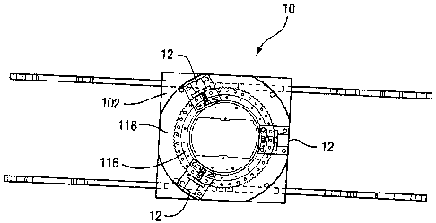
[0022] Referring to FIGURE 2, the measurement system 10 according to the
present invention includes a plurality of load sensors 12 secured to a
turntable bearing
118 disposed between the vehicle chassis or frame 102 and the turntable 116.
As shown,
the measurement system 10 includes three load sensors 12 that are placed about
a
periphery of the turntable bearing 118 at 120 intervals. Additional or fewer
load sensors
12 may be alternatively used for calculating a rotational moment applied to
the vehicle
frame, and the invention is not necessarily meant to be limited to the three
load sensors
shown. Additionally, the load sensors 12 need not necessarily be positioned
equidistant
about the periphery of the turntable bearing 118. The turntable is typically
attached to the
bearing at several points (typically, twenty-four bolts). For economic and
other reasons,
it is preferable to minimize the number of load pins or load cells, with the
preferable
niinimum number to be used being three. By doing so, in order to maintain the
bearing
specifications on maximum allowable deflection, a structural ring may be added
to take
all the additional deflection introduced by the substantially lower number of
attachments
(i.e., three load sensors 12 versus twenty-four attachment bolts).
[0001] The load sensors 12 measure vertical forces on the turntable bearing
118.
Any suitable load sensors that can measure a vertical load according to
relative parts may
be used. An example of a suitable load sensor is the 5100 Series Load Pin
available from
Tedea-Huntleigh International, Ltd., of Canoga Park, California. The sensors
12
communicate with a controller 112', which communicates with the vehicle drive
arrangement, and the controller 112' calculates a rotational moment applied to
the vehicle
frame 102 from the turntable 116 by processing vertical forces on the
turntable bearing
6
548956
CA 02430034 2003-05-26
118 measured by the load sensors 12. In this context, the controller 112'
calculates the
rotational moment based on relative vertical forces measured by the load
sensors. With
reference to FIGLJRES 3-5, an exemplary formula for calculating the rotational
moment
on the vehicle frame 102 based on the vertical forces on the turntable bearing
118
measured by the load sensors 12 can be expressed as follows:
arctan',and
2P - P2 - P3
8=~ or 0 +n (depending on location of counterweight 116), where
M = - ~ R(P2-P3)sin8+ ~ R(-2P1+P2+P3)cos6,
where M is the rotational moment on the vehicle frame 102 based on vertical
forces on
the turntable, R is the radius of a circle CR intersecting the three load
sensors, Pi-P3 are
the load cell readings on the turntable, and 0 is the turntable swing angle.
[0024] Because the system can determine the swing angle from the load sensor
readings, it is therefore relatively easy to have a better stability envelope
with no need of
additional sensors to measure the swing angle. Rather, the orientation of the
boom (over
front side or over rear side of chassis) can be sensed by utilizing the
currently existing
limit switch for the oscillating axle lock-out system. Lifts with no
oscillating axle can be
fitted with a similar simple switch system.
[0025] The resulting moment can be used to assess the stability of the machine
and control operation of the machine components. In operation, an upper bound
and a
lower bound for the resulting moment are set based on characteristics of the
machine
(e.g., boom length, height, weight, swing angle, etc.). The upper and lower
bounds can
be determined experimentally or may be theoretical values. When the measured
moment
is close to the upper bound, the machine is close to forward instability. When
the
measured moment is close to the lower bound, the machine is close to backward
instability. As the machine approaches forward or backward instability,
operation of the
machine can be controlled via the controller 112' to prevent the resulting
moment from
surpassing the upper or lower bounds.
7
548956
CA 02430034 2003-05-26
[0026] In addition to calculating the rotational moment applied to the frame
through the turntable, the load sensors 12 can be used to derive the load in
the platform
by:
Load=P1+P2+P3-W,
where W is a constant and known weight of the upper structure including, e.g.,
boom
platform, control box. Still further, by mounting the load sensors 12 to the
turntable
bearing 118, the system can also account for external forces on the boom or
the like that
may affect stability. Conventionally, only the load in the platform is
monitored. These
conventional systems therefore cannot accommodate stability variations that
may be
caused by the boom or platform colliding with an external object, such as a
beam or the
like or even the situation when the boom itself is used to lift the vehicle or
something
other than a load in the platform.
[0027] With the system according to the present invention, a boom lift or
other
lifting vehicle can be operated more safely by monitoring a rotational moment
applied to
the vehicle frame from the turntable according to vertical forces on a
turntable bearing.
As a consequence, a tipping hazard can be reduced or substantially eliminated.
By
monitoring the moment in this manner, the system of the invention can
accurately and
continuously assess true forward and backward tipping moments. As a result,
the system
can effect a continuous rated capacity as opposed to the current dual rating
(such as fully
extended, fully retracted). In addition, the upper and lower bounds can enable
continuously more capacity with decreasing ground slope (using a chassis tilt
monitor),
and continuously more capacity from boom over the side to boom over front/back
(conventionally, only rated for worse configuration - boom over the side). By
monitoring
the load applied to the frame from the turntable, the system can detect
imminent tipping
due to external forces, other than load in the platform. Design requirements
can be
relaxed, and machines can be pre-programmed for different reach and capacity.
The
system can derive/determine the load in the basket, thereby helping to prevent
structural
overload of basket attachments and the leveling system. By monitoring moments
and
8
548956
CA 02430034 2003-05-26
weight in the basket, the system can be used to store information about
occurrence of
excessive loads, such information can be used when responding to warranty
claims.
[0028] While the invention has been described in connection with what is
presently considered to be the most practical and preferred embodiments, it is
to be
understood that the invention is not to be limited to the disclosed
embodiments, but on
the contrary, is intended to cover various modifications and equivalent
arrangements
included within the spirit and scope of the appended claims.
9
548956