Note: Descriptions are shown in the official language in which they were submitted.
CA 02430105 2003-05-27
- 1 - .
ANTENNA, IN PARTICULAR MOBILE RADIO ANTENNA
The invention relates to an antenna, in particular a
mobile radio antenna, as claimed in the
precharacterizing clause of claim 1.
Mobile radio antennas for mobile radio base stations
are normally constructed such that a number of
radiating element arrangements are provided, located
one above the other in the vertical direction, in front
of a reflector plane. These radiating element
arrangements may thus comprise a large number of dipole
radiating elements, for example in the form of crucible
dipoles, in the form of a dipole square etc., that is
to say in the form of radiating element types which
have a dipole structure. Antennas in the form of
so-called patch radiating elements are likewise known.
As is known, various mobile radio frequency bands are
provided, for example the 900 MHz frequency band for
the so-called GSM 900 network, the 1800 MHz or, for
example, the 1900 MHz frequency band, as well, for the
so-called GSM 1800 network, as is normally used in the
USA and in a large number of other countries. A
frequency band around 2000 MHz has been provided for
the next mobile radio generation, namely the UMTS
network.
It is thus normal to design such mobile radio antennas
as at least dual-band antennas, although triple band
antennas may also be used (for example for the 900 MHz,
for the 1800 and 1900 MHz or, for example, for the
2000 MHz band).
CA 02430105 2003-05-27
- 2 -
Furthermore, the antennas are preferably designed as
dual-polarized antennas for operation with
polarizations of +45 and -45 . It is also normal for
antennas such as these to be protected against weather
influences by a plastic shroud. This so-called radome
has to achieve objects which are primarily mechanical
and surrounds all the radiating antenna'parts to the
same extent. An antenna such as this for operation in
at least two frequency bands that are offset with
respect to one another has been disclosed, by way of
example, in DE 198 23 749 Al.
However, one problem that frequently arises with
two-band antennas or with multiband antennas in general
such as these is that the 3dB beam widths of the polar
diagram in the azimuth direction differ widely for the
different frequency ranges, that is to say for the
different frequency bands. A further problem that
occurs with two-band antennas, or with multiband
antennas in general, is that cross-polar components can
occur, which lead to a deterioration in the polar
diagram characteristic. Finally, however, the VSWR
ratio and/or the decoupling may also be
disadvantageously influenced.
In principle, a large number of antennas are known from
the prior art which are designed, however, for only a
single frequency band, that is to say they can receive
and transmit in only one frequency band. These may be
linear-polarized or else dual-polarized antennas for
transmission in only this said one frequency band.
Antennas such as these which operate in only one
frequency band are disclosed, for example, in the
publications DE 199 01 179 Al, DE 198 21 223 Al,
DE 196 27 015 C2, DE US 6,069,590, A and US 6,069,586 A.
All these prior publications deal with different types
of problems, however, in general with the question of
decoupling two polarizations in the same frequency
band. Electrically conductive parts are generally used
CA 02430105 2005-01-25
-3-
for this purpose, in order to produce decoupling elements that radiate
parasitically.
In contrast, and against the background of the antenna disclosed in
DE 198 23 749 Al, which forms this generic type, the object of the present
invention is to provide a corisiderable improvement (irrespective of whether
the
antenna is operated with only one polarization or with a number of
polarizations),
at least for operation in two frequency bands, with regard to the 3dB beam
width
and/or with regard to the suppression of the cross-polar component and/or of
the
VSWR ratio and/or with regard to decoupling and increasing the bandwidth.
According to the invention, there is provided an antenna, for operation in at
least
two frequency bands, comprising:
a reflector,
a protective shroud comprising nonconductive material,
plural antenna radiating elements disposed between the protective shroud
and the reflector, said plural antenna radiating elements including at least
one
lower frequency band radiating element and at least one upper frequency band
radiating element, the lower frequency band radiating element being disposed
at a
first distance from the reflector, the higher frequency band radiating element
being
disposed at a second distance, from the reflector, said second distance being
less
than said first distance, a region being defined between the first distance
and the
second distance, and
at least one dielectric body which does not forn-s the protective shroud, more
than 40% of the volume and/or more than 40% of the weight, of the at least one
dielectric body being disposed within said region between the upper frequency
radiating element and the lower frequency radiating element.
According to the invention, there is also provided an antenna having a
reflector,
the reflector defining a plane, the antenna comprising:
a protective shroud comprising nonconductive material,
CA 02430105 2005-01-25
- 3a -
plural radiating elements disposed between the protective shroud and the
reflector, said plural radiating elements comprising at least a lower
frequency band
radiating element and at least an upper frequency band radiating element, the
radiating elements for the lower frequency band being disposed at a first
distance
range from the reflector, the radiating elements for the higher frequency band
being disposed a second distance range from the reflector, said second
distance
range being closer to said reflector than said first distance range, a
distance area
being defined parallel to the reflector between the upper frequency radiating
elements and the lower frequency radiating elements, and
at least one dielectric body which does not form the protective shroud, at
least part of the dielectric body being disposed in the distance area which
extends
parallel to the reflector and is defined by the radiating elements for the
lower
frequency band and by the radiating elements for the upper frequency band, the
dielectric body comprising an extent component which runs toward the plane of
the reflector and is longer than its extent direction which runs at right
angles to the
plane of the reflector, and/or than its distance from the plane of the
reflector.
According to the invention, there is also provided an antenna of the type
including
a reflector, the antenna comprising:
a protective shroud composed of nonconductive material,
radiating elements arranged between the protective shroud and the
reflector, said radiating elements including lower frequency band radiating
elements and upper frequency band radiating elements, the radiating elements
for
the lower frequency band being arranged at a first distance, or in a first
distance
range, in front of the reflector, the radiating elements for the higher
frequency band
being arranged at a second distance, or in a second clistance range, in,front
of the
reflector, said second distance or second distance range being closer to said
reflector than said first distance or first distance range, at least one of
said higher
frequency band radiating elements and said lower frequency band radiating
elements being arranged in a dipole square, and
CA 02430105 2005-01-25
-3b-
at least one dielectric body which does not fornn the protective shroud, said
dielectric body being arranged in a vertical plan view of the reflector such
that the
dielectric body is located at the same level as and within the dipole square,
the
dielectric body having a surface area defined by a right-angle projection onto
the
plane of the reflector, the size of said surface area being larger than the
square of
the linear distance which is obtained from the distance between the plane of
the
reflector and at least one of:
(1) the dielectric body,
(2) the distance between the plane of the reflector and a center plane which
runs through the dielectric body, and
(3) the distance between the plane of the reflector and the outer boundary
surface of the dielectric body, facing away from the reflector plane.
According to the invention, there is also provided an antenna comprising:
a protective shroud composed of nonconductive material,
plural radiating elements arranged underneath the protective shroud and in
front of the reflector, said plural radiating elements including lower
frequency band
radiating elements and upper frequency band radiating elements, the radiating
elements for the lower frequency band being disposed at a first distance, or
in a
first distance range, in front of the reflector, the radiating elements for
the higher
frequency band being arranged at a second distance, or in a second distance
range, in front of the reflector, the higher frequency band radiating elements
being
closer to the reflector than the lower frequency band radiating elements, and
at least one dielectric body which does not form the protective shroud, at
least part of the dielectric body extending above parts of the radiating
elements at
a distance in front of the reflector, the dielectric bc-dy extending para(lei
to the
reflector, and when viewed in a vertical plan view of the reflector, having a
flat
extent which is greater than the flat extent, attachrr-ent elements being
coupled to
the dielectric body, said attachment elements running toward the reflector.
CA 02430105 2005-01-25
- 3c
According to the invention, there is also provided a plural-band antenna
comprising:
a reflector,
at least one lower frequency band radiating element disposed a first
distance from the reflector,
at least one upper frequency band radiating element disposed a second
distance from the reflector, wherein said first distance is greater than said
second
distance, and
a dielectric body at least partially disposed between said at least one upper
frequency band radiating element and said at least one lower frequency band
radiating element, said dielectric body improving upper frequency band antenna
performance characteristics substantially without degrading lower frequency
band
antenna performance.
The following provides an outline of certain possibly preferable features of
the
invention which are to be considered non-restrictively and which will be more
fully
described hereinafter.
It must be regarded as extremely surprising that the advantages mentioned
above
are improved not just individually but also cumulatively on their own in that
a
dielectric body is provided for a mobile radio antenna which is known per se,
which
dielectric body has at least one extent direction parallel to the reflector
plane that
is larger than its extent component which runs at right angles to the
reflector plane.
The dielectric body according to the invention is preferably in the form of a
plate. In
particular, in a plan view, it may be in the form of an n-sided polygon, and
may
extend, for example, above a dipole radiating element arrangement, for example
a
cruciform dipole, a dipole square or a patch radiating element, with the
extent
position being located above the corresponding radiating elements for a higher
frequency band and below the radiating elements at least for the lowest
frequency
band.
~ CA 02430105 2003-05-27
- 4 -
Furthermore, the dielectric body according to the
invention, which is also referred to as a dielectric
tuning plate in places in the following text, is
symmetrical when seen in a plan view, and, above all,
may have at least sections which are designed to be and
are arranged symmetrically with respect to an
individual radiating element arrangement.
Furthermore, it has also been found to be advantageous,
in addition or alternatively, to arrange corresponding
dielectric bodies at a distance in front of the
reflector plate, between two radiating element
arrangements which are generally arranged located one
above the other in the vertical direction in front of a
vertical reflector plane.
The dielectric bodies according to the invention may,
for example, be composed of suitable plastic material,
for example polystyrene, glass fiber reinforced plastic
(GFRP) etc.
A material whose dielectric does not have a high loss
factor is preferably used for the dielectric body.
The invention has a particularly advantageous effect,
for example, in the frequency bands from 800 to
1000 MHz and from 1700 to 2200 MHz.
The dielectric body is preferably in the form of a
plate and extends in a parallel plane in front of the
reflector. However, it may also be provided with
attachment devices or stand feet (in general spacers
etc.) which are composed of the same material, in order
to arrange it at a predetermined distance, which has
been found to be advantageous, in front of the
reflector plate. The extent height is preferably less
than X/2.
CA 02430105 2003-05-27
- 5 -
The antenna according to the invention makes it
possible to achieve a considerable reduction in the
frequency dependency of the 3dB beam width. Mobile
radio antennas are frequently set such that they have a
3dB beam width of 65 . This 65 3dB beam width can,
however, normally not be set completely identically for
the at least two frequency bands, particularly if these
are very broad bands. A discrepancy with regard to the
at least two intended frequency bands of, for example,
65 10 (or at least 7 ) is normal in the prior art.
According to the invention, this discrepancy can now be
improved to 65 5 .(or even only 4 or less).
As is known, the antennas are frequently adjusted such
that they each emit in a horizontal 120 sector angle.
This is also referred to as a sector. Three sectors are
thus formed per antenna mast. A corresponding mobile
radio antenna thus transmits at an angle of +60 or
-60 at the sector boundaries, with the suppression of
the cross-polar components, especially at the sector
boundaries according to the prior art, having poor
values, particularly- in the case of broadband antennas.
The antenna according to the invention using the
dielectric tuning body in this case allows a ratio of
10 dB or even better to be achieved, even at the sector
boundaries at 60 , with regard to the suppression of
the cross-polar component.
If - although this is not absolutely essential
according to the invention - cross-polarizing radiating
elements are used in a multiband antenna arrangement
(that is to say at least in a dual band antenna
arrangement), then the decoupling can likewise be
improved considerably in this case. The required
decoupling is in the order of magnitude of more than
30 dB. This is a very major problem, particularly in
the case of broadband antennas or antennas with an
electrically adjustable notch. The antenna according to
the invention considerably exceeds this value, in
CA 02430105 2003-05-27
_ 6 _
particu lar and even when the antennas have a broad
bandwidth and are also electrically adjustable.
Finally, a further positive factor is bandwidth
broadening, especially for the higher frequencies.
In summary, it can thus be stated that the advantages
mentioned above with the dielectric body according to
the invention have a positive effect especially for the
higher frequency band or the intended number of
frequency bands, with the measures according to the
invention having virtually no influence on the lower
intended frequency bands, or in each case on the lowest
intended frequency bands.
The invention will be explained in more detail in the
following text with reference to two exemplary
embodiments. In this case, in detail:
Figure 1 shows a schematic plan view of a first
exemplary embodiment of an antenna
according to the invention for the
mobile radio field, with a number of
radiating elements and a dielectric body
provided according to the invention;
Figure 2 shows a schematic transverse face view
at right angles to the vertical
longitudinal extent of the antenna shown
in Figure 1;
Figure 3 shows a vertical end face view of the
antenna shown in Figures 1 and 2;
Figure 4 shows a plan view of an exemplary
embodiment modified from that in
Figure 1;
CA 02430105 2003-05-27
- 7 -
Figure 5 shows a corresponding transverse face
view of the antenna shown in Figure 4;
Figure 6 shows an end face view (of the antenna
shown in Figures 4 and 5);
Figure 7 shows a schematic plan view of a
dielectric body which is composed of a
number of parts; and
Figure 8 shows a schematic cross-sectional
illustration of a dielectric body
provided with spacers or feet.
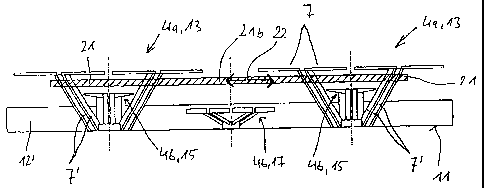
In a first exemplary embodiment as shown in Figures 1
to 3, the antenna 1 has five individual radiating
elements, namely two first radiating elements 4a, which
are located offset with respect to one another in the
vertical direction, for a first, lower frequency band,
and three second radiating elements 4b, which are
offset in the vertical direction, for a higher
frequency band.
The first radiating elements 4a are dipole radiating
elements 7, which are arranged in the form of a dipole
square 13, are held via so-called balancing devices 7',
at least some of which run to a common center point,
and are attached to an electrically conductive
reflector 11.
The second radiating elements 4b, which are arranged
within these first radiating elements 4a, are formed in
the illustrated exemplary embodiment on the basis of a
cruciform dipole 15 with two mutually perpendicular
dipoles.
The central radiating element device 4b, which is
provided between the first radiating elements 4a and
likewise belongs to the group of second radiating
CA 02430105 2003-05-27
- 8 -
elements 4b, once again in this exemplary embodiment
likewise comprises a dipole square 17 which is formed
from four dipoles 16 and which, in principle, is
comparable to and similar to the large dipole squares
of the first radiating elements 4a.
The radiating elements which have been mentioned are
arranged in front of the vertically aligned reflector
11, in which case the reflector 11 may be formed, for
example, from a reflector plate 11', to be precise with
two edge sections 12', which are placed on its vertical
sides 12, from the reflector plane, in the emission
direction.
As can be seen from the illustrations in Figures 1 to
3, a dielectric body 21 is, furthermore, provided in
,order to improve various antenna characteristics, which
dielectric body 21 in the illustrated exemplary
embodiment is in the form of a plate and extends at
least essentially parallel to the reflector plane. It
is preferably located at a distance in front of the
reflector plane which is less than X/2 of the highest
transmitted frequency band, or is less than X/2 of the
associated mid-frequency of the highest frequency band.
The thickness of the dielectric body may be chosen to
be different, within wide limits. Good values are
between 2% and 30%, in particular between 5% and 10% of
the distance between the individual first radiating
elements 4a and the associated reflector 11.
As can be seen in particular from the plan view shown
in Figure 1 in comparison to the two side views shown
in Figures 2 and 3, the dielectric body 21 has at least
one extent component 22 which runs parallel to the
plane of the reflector 11 and is larger than its
thickness and/or is larger than the distance between
its center plane and the plane of the reflector 11,
and/or is larger than the distance between the
radiating elements 4b, 15 of the radiating elements
~ CA 02430105 2003-05-27
- 9 -
which are provided for the upper.frequency band and the
associated plane of the reflector 11.
Finally, it has likewise been found to be advantageous
for the dielectric body to be arranged entirely or at
least with a part of it at a distance in front of the
reflector 11, to be precise above the radiating element
arrangement which is intended for the upper frequency
band. It has likewise been found to be advantageous for
the dielectric body to be arranged entirely or at least
with a part of it underneath the radiating element
arrangement which is intended for the lower frequency
band. Both the conditions mentioned above should
preferably be satisfied at the same time, with the
effect being particularly advantageous if the
dielectric body 21 is thus entirely, or with at least
one section, located above the radiating element
arrangement which is provided for the upper frequency
band, while at the same time being located underneath
the radiating element arrangement which is provided for
the lower frequency band, and in the process extending
entirely or essentially parallel to the reflector. If
the dielectric body is not located entirely above the
radiating elements which are provided for the upper
frequency band and is not located entirely underneath
the radiating elements which are intended for the lower
frequency band, then the effect is particularly
advantageous if, with respect to its overall volume
and/or its overall weight, the dielectric body 21 is
located at least to an adequate extent in this
position, that is to say for example with more than at
least 30%, 40%, 50%, or, in particular, with more than
60%, 70%, 80% or 90% of its entire weight and/or volume
located in the stated region.
In this case, the illustrated exemplary embodiments
also show that, in the projection at right angles to
the reflector 11 located underneath it, the at least
one dielectric body 21 is smaller than the reflector
CA 02430105 2003-05-27
- 10 -
plate. In fact, the dielectric body may also be of a
size which, in the end, corresponds to a size that is
larger than the reflector 11.
In the illustrated exemplary embodiment, a first
section of the dielectric body 21 is arranged
symmetrically within the first radiating elements 4a
and thus above the second radiating elements 4b which
are located in it, to be precise in a square shape in
the illustrated exemplary embodiment - since the first
radiating elements 4a are formed from a dipole square.
The dielectric body 21 that is formed in this way, that
is to say the dielectric tuning plate 21, is provided
in the illustrated exemplary embodiment with a central
vertical section 21b, which connects the sections 21a
in the region of the dipole squares 13 of the two first
radiating element arrangements 4a, which are offset
with respect to one another in the illustrated
exemplary embodiment. Thus, in the illustrated
exemplary embodiment, the dielectric tuning plate 21
which is formed in this way is integral. However, it
could also be composed of a number of parts, which
correspond at least approximately to the shape shown in
Figure 1, that is to say having two sections 21a which
form a square and which, corresponding to the dipole
square 13, are each arranged concentrically in respect
thereto, parallel to the reflector plane. The longer
connecting section 21b could then be provided such that
it runs between these two sections 21a.
Particularly for the higher frequencies, for example
from 1700 to 2200 MHz (for example 2170 MHz), this
allows the 3dB beam width, the value for the
suppression of the cross-polar component, the
decoupling and also the increase in bandwidth to be
improved in an advantageous manner. Virtually no
disadvantageous influences can be found for the lower
frequency band or the low frequency bands.
CA 02430105 2003-05-27
- 11 -
As can be deduced only indirectly from the drawings,
the die 1 ectric body is preferably mechanically attached
to the radiating elements, for example at their
balancing devices.
The exemplary embodiment shown in Figures 4 to 6
differs from that shown in Figures 1 to 3 in that patch
radiating elements 27 are used for the second radiating
elements 4b (instead of the cruciform radiating
elements 15), that is to say flat radiating elements,
for example in the form of a square radiating element,
which are aligned at a suitable distance in front of
the reflector 11, centrally and symmetrically, with the
same polarization alignment with respect to the first
radiating elements 4a. A further patch radiating
element 27 is also provided, located in the center,
between the two patch radiating elements 27, which are
each provided in the first radiating element 4a, and
this further patch radiating element 27 may be located
at a different height, as can be seen in particular
from the longitudinal face illustration shown in
Figure 5, and from the end face view shown in Figure 6.
However, the rest of the first dipole radiating
elements 4a, which are in the form of a dipole square,
could likewise be replaced by patch radiating elements,
so that the antenna is in the form of a patch antenna,
overall.
With this antenna as well, a corresponding dielectric
body 21 is provided as the dielectric tuning element or
as the dielectric tuning plate 21, as can be seen from
the illustrations.
The dielectric body 21 can be anchored and held in a
suitable way for example on the balancing devices 7' on
the individual radiating elements. It can also be
provided with stand feet which are likewise, for
CA 02430105 2003-05-27
- 12 -
example, formed from dielectric or from metal, that is
to say they may also be conductive.
The die l ectric body 21 need not be integral. It may
also be formed from a number of isolated separate
subsections, which are then effectively joined together
to form a desired shape, in which case it is irrelevant
if the individual elements from which the dielectric
body 21 can be formed do not lie completely flat
together in the fitting direction but, for example in a
schematic plan view shown in Figure 7, are located such
that spacing gaps 31 remain between the individual
elements.
Figure 8 will now be used to show, only schematically
with respect to a cross section through the element 21,
how the dielectric tuning element or the dielectric
body can also be provided with spacers for attachment
to the reflector 21, in which case the spacing elements
41 may be separate spacers or may be composed of the
same material as the dielectric body 21 itself. Where
and in what size the spacers are formed can be varied
as required within wide limits.
The shape may also differ within wide limits. The shape
may in this case be changed such that the desired
advantageous antenna characteristics can be produced
and implemented.