Note: Descriptions are shown in the official language in which they were submitted.
CA 02431224 2003-06-06
WO 02/45978 PCT/NZO1/00271
Title
Amphibious catamaran
Background art
s Amphibious craft necessarily compromise between adequate water and
adequate land performance. Shortcomings frequently exist on entry to, or exit
from water onto land.
It was an object of the present invention to yield an amphibious catamaran
with
to improved performance or at least to provide the public with a useful
choice.
Disclosure of the invention
The present invention broadly consists in an amphibious catamaran
comprising:
is two spaced apart hulls;
a framework supporting the hulls;
a motor supported by the framework;
a drive unit for water propulsion actuated by the motor in use;
at least 3 land wheels;
2o two sub-frames, each supporting one or more land wheels;
height adjustment means enabling, in use, one of the sub-frames to be
moved with respect to the framework from a position where the land
wheels stably support the catamaran for travel on land, with the
CA 02431224 2003-06-06
WO 02/45978 PCT/NZO1/00271
hulls clear of the land, and a position where its associated land
wheels are raised upwardly above the bottoms of the hulls;
drive means for land propulsion coacting with one or more of said land
wheels;
s steering means for steering the craft on water and on land;
and an input station for any person who is to operate the craft on water
or on land, or for receiving remote signals to control the operation in
use, or both purposes.
to An important feature is that the hulls, whether they be rigid or not, are
securely
fixed to a framework. The forces exerted by water on hulls can be appreciable
and this invention eliminates the need for relative movement between the
hulls. For example, some other constructions attempting to provide an
amphibious craft pivot the hulls about their framework (so that the land
wheels
Is can be rotationally fixed to the framework).
With this invention, however, advantage is taken of the fact that land
stresses
via the land wheels to the framework via the sub-frames are more easily taken
care of and thus the land wheels are made to be vertically movable with
2o respect to the framework. Also the framework is able to be kept as compact
as possible which means stresses are more easily accommodated.
CA 02431224 2003-06-06
WO 02/45978 PCT/NZO1/00271
There is preferably a single motor (preferably a turbo-diesel) providing the
motive power for operating all the equipment including driving an hydraulic
pump, or pumps, which form part of drive means for land propulsion and which
include an hydraulic motor driving each driven land wheel. Similarly the pump
or pumps form part of the drive unit for water propulsion which includes an
hydraulic motor driving a propeller.
Preferably one or more hydraulic pumps also form part of the land and water
steering means which also includes rams or hydraulic motors and they also
io form part of the height control means via rams controlling the movement of
the
sub-frames. The hydraulic motors should be reliable in service as water
ingress is impeded by internal oil pressure and they are mostly out of the
water. There might also be a favourable automatic distribution of power to the
motors exerting the greatest effort if they are hydraulically in series.
is
The hulls are preferably wholly or partly non-rigid and preferably wholly or
partly inflatable as that has a number of advantages. Non-rigid hulls partly
absorb forces from the water thus reducing the structural strength needed for
the framework and are less prone to being damaged or causing damage or
2o injury. The turbo-charger of the diesel motor is preferably used to enable
rapid
inflation and deflation of the hulls.
CA 02431224 2003-06-06
WO 02/45978 PCT/NZO1/00271
At least the front land wheels would preferably be steered. It is actually
preferred to oppositely steer both front and rear land wheels to gain an
improved turning circle. Also crab-steering is preferably provided.
s Many of the functions of the hydraulics and other systems may be computer
controlled.
The front and rear sub-frames carry the land wheels at their extremities and
are arranged to give leading and trailing arm suspension respectively. The
to extremities can preferably be swung through appreciable arcs, it being
preferable to take them totally out of the water to maximise on-water
performance. At their maximum lowering to elevate the hulls a maximum
height, the hulls might preferably be totally out of the water while the land
wheels might still be wholly or partially submerged. This yields improved
is traction for beaching the craft and a reduced turning circle as the
wheelbase is
reduced. An intermediate position would suit safer on-road travel.
By way of explanation "land" when used in this specification includes seabed
or any submerged land or any other reasonably solid surface such as a carrier
2o ship loading ramp.
4
CA 02431224 2003-06-06
WO 02/45978 PCT/NZO1/00271
Also the expression "land wheel" is intended to include both conventional
wheels and other means of imparting horizontal movement of the craft with
respect to land by utilizing frictional contact with the land.
s Description of the drawings
The above gives a broad description of the present invention one preferred
form of which will now be described with reference to the accompanying
drawings in which all figures are highly schematic and do not show accurate
constructional details:
to Fig. 1 shows a side view of the craft with the hulls at maximum elevation
above land
Fig. 2 shows a side view of the craft in normal on-water travelling mode
Fig. 3 shows a side view of the craft in normal on-land travel-at-speed
mode
is In both Figs 2 and 3 and the remaining figures some of the finer detail of
Fig. 1 is omitted for clarity.
Fig. 4 shows an outward view to the left from a plane just central of the
motor and steering arrangements of the right front land wheel
Fig. 5 shows the drive unit and depth control means in side view
2o Fig. 6 shows a cross-section through a hull exploded from a
cross-section of a mating portion of the framework
Fig. 7 shows tail adjustment means and
Fig. 8 shows a plan view from above.
s
CA 02431224 2003-06-06
WO 02/45978 PCT/NZO1/00271
Modes for carrying out the invention
The hulls and framework
s In a preferred form of the invention as best shown in Figs 1 and 8 an
amphibious catamaran has two long, non-rigid, substantially cylindrical,
partly
inflatable hulls 1,2 perhaps 6 to 7 metres long. These may be spaced apart in
parallel a distance so that, at least when deflated, the total width of the
craft is
at or within the maximum width allowed for road travel without an oversize
1o permit being required. The hulls are kept in their positions by means of a
framework 3 of sufficient strength to resist the high forces exerted on the
hulls
under certain conditions found on the water. The framework might be a
fabricated stainless steel, or aluminium, or moulded fibre-reinforced resin
composite, open-topped box structure comprising (but not illustrated) a floor
is and sides and ends and cross members, some of which might be hollow to
provide emergency buoyancy or fluid storage spaces. As it is normally above
water level the floor can be self draining.
The hulls are preferably of a diameter of about 650mm although that would
2o vary from one craft to another, depending on the layout and weight etc.
However, with that dimension, which would be typical, the outer 25mm could
be a closed-cell soft or flexible foam wrapping 4 (Fig. 6) around each
inflatable
tube 5. The wrapping would be encased in the usual protective fabric 6 which
6
CA 02431224 2003-06-06
WO 02/45978 PCT/NZO1/00271
would substantially or wholly provide the outer surface of the hull. There
could
be multiple fabric layers. The idea of the foam is to provide additional
protection against deflation of the interior tubes (there being say three in
all in
series) if the hull should become snagged by a fish hook or impaled on some
projection, such as a sharp rock. Shapes such as longitudinal strakes of
closed-cell foam (not shown) could also be attached to or incorporated under
the fabric. The foam helps the inflatable hulls to maintain their shapes as
otherwise there is a tendency for them to deform. A craft with these hulls
might draw about 300mm of water.
~o
The longer the hulls the better the craft handles waves or rough seas by being
able to bridge a longer pitch between waves.
The lower-most part of each hull has adhered to a fabric layer 6 a semi-rigid
~s external boot 7 comprising a band of suitable plastics material which can
impart a suitable shape to the bottom of the hull while also protecting the
underlying fabric against abrasion if the hull touches land during beaching
etc.
That reinforcement serves to partially rigidise the lower-most portion of the
hull, while yet allowing much of the impact of waves against the hull to be
2o borne by the flexible portion of the hull above it. It functions as a
strong-back.
Furthermore, it can serve as a mounting for a keel 9, which might be
necessary to improve directional performance and to stop chine-walk.
CA 02431224 2003-06-06
WO 02/45978 PCT/NZO1/00271
The boot 7 generally has a cupped shape and it might be just, say, 150mm
wide or it might encase the lower third of the hull, for instance. It can be
extended to the forward part of the hull and a more appropriate shape in that
area would be a "V" shape, possibly with a packer between the boot and the
s round hull. The boot is made of a semi-rigid material which retains its
shape
against permanent deformation, perhaps nylon or polyethylene, and must be
able to be adhered or welded to the protective fabric 6.
A modification is to have an inner "extension"10 of the boot to form a semi-
rigid
to strong-back internal of the fabric 6 but separated from an inflatable tube
5 by
an innermost layer of foam 11 while being embedded in outer foam layers and
overlaid by the fabric. This extension 10 further reduces the tendency for
deformation of the hulls and provides an improved mounting frame for a keel.
While the extension would act in conjunction with the boot 7 its shape might
be
is completely different. For example it might be provided as a narrow beam
with
its depth arranged to be vertical in use as shown in Fig. 6 and the depth
might
alter along the hull length.
The boot, or preferably any keel mounted on it, can be grounded by lowering
2o to act as a brake for the craft upon transition from water to land, if the
approach is made too fast.
s
CA 02431224 2003-06-06
WO 02/45978 PCT/NZO1/00271
Each hull 1,2 is fastened to the framework 3 by means of a bolt-rope track
coupling 12,12'; 13,13' on either side of the hull top centre-line. Thus, when
the catamaran is supported on its land wheels the hull can be slid out of the
track for maintenance, which frequently might require inversion of the hull.
This is a feature which is very advantageous where the catamaran is perhaps
being used as a rescue craft and needs to be in a perpetual state of readiness
as far as possible. A spare hull could be fitted quite quickly, or repairs
could
be made quite quickly.
to The inflation of the hull is preferably from the turbo-charger of a turbo-
diesel
motor 14. This provides a large quantity of low pressure air and also provides
a means of quickly evacuating the air from the hulls. There would be suitable
attachments (not shown) to the turbo-charger inlet and outlet and a suitable
manifold (not shown) to the inflatable tubes.
is
The three serially-mounted tubes which are inflatable within each hull may be
removed through side access flaps (not shown) in the outer covering fabric 6
and slits in the underlying foam,for repair purposes when needed.
2o The objective of the hull design is to provide a design which acts well as
a
displacement hull, is capable of planing efficiently, which is easy to service
or
repair, and which is relatively resistant to damage while providing a means of
absorbing as much of the shock forces caused by water impact as possible.
CA 02431224 2003-06-06
WO 02/45978 PCT/NZO1/00271
The boots 7 help with ride softness by retaining the hydrodynamic round shape
of the hulls on impact with a wave, thus maintaining the speed of the craft.
Directly above the hulls, supported on the sides of the framework, there may
s be detachable rigid sealed containers (not shown) adapted to carry tools,
equipment and supplies but also capable of functioning as additional flotation
in a case where the craft is under a heavy load or when travelling through
rough seas.
to For extreme safety the inflatable tubes 5 might themselves contain
emergency
inflatable tubes (not shown), held up high out of harm's way when deflated,
which can be filled with air from the turbo-charger, or emergency air
reservoir,
if ever needed.
is The bow or nose 15,16 of each hull can include a tapered closed-cell solid
foam core, overlaid by said sheath of closed-cell flexible foam, which in turn
is
overlaid by the protective fabric. The nose is preferably able to be tilted up
to
a beaching position via a double-acting ram 17 as shown in Fig. 1.
2o The stern or tail section 19,20 of each hull is able to be pushed down or
pulled
up, or both, with respect to the remainder of the hulls 1,2 by tail adjustment
means preferably operating via a double-acting ram 18 (Fig 3 and Fig 7).
io
CA 02431224 2003-06-06
WO 02/45978 PCT/NZO1/00271
Each tail 19,20 is also preferably able to be selectively deflated to enable
the
tail to be pulled up and contracted to facilitate raising or lowering of a
rear land
wheel such as 42 past the tail or stern as is shown in Fig. 7.
s On water propulsion
The motor 14 is supported by the framework 3 as is a drive unit 21 for water
propulsion. This may be a propeller or a jet drive. The preferred option is an
hydraulically driven propeller 22 (Fig. 5) mounted on a depth control means 23
which includes a parallelogram linkage enabling the propeller to be lowered
to deep enough to function properly below the foul water created in the tunnel
between the hulls, while enabling it to be raised high enough to avoid damage
when the craft is on, or close to, land, maintaining trim all the while. A
single
or double-acting ram 27 controls propeller height. Conventional stern-legs are
not strong enough nor do they have sufficient reach, nor maintain trim when
is raised. They could also foul the legs or arms 54,55 of the rear sub-frame
45
(yet to be described) if raised while at or close to a full-lock position as
the
distance between the rear legs is only about 900mm.
The top 24 and/or bottom 25 arms of the parallelogram linkage are adjustable
2o in length to alter the trim of the propeller. The top and/or bottom arms
preferably incorporate double-acting pneumatic or hydraulic rams such as ram
26 to effect length adjustment.
n
CA 02431224 2003-06-06
WO 02/45978 PCT/NZO1/00271
Rotation of the parallelogram linkage, or the propeller mounted on it, about a
substantially vertical axis such as 29,29', in use, for steering the craft on
water,
is achieved by another hydraulic motor or a ram or rams (not shown). A
conventional outboard motor can move only about 30°to either side of
centre
but the system for this craft preferably allows much more turning.
The propeller is hydraulically driven via a, usually unsubmerged, reversible
hydraulic motor 30 driving a substantially vertical partially submerged shaft
(not shown) which drives the propeller via a submerged pair of bevel gears
to (not shown) in use, all submerged parts being suitably encased in casing 31
and perhaps water-cooled as well.
To achieve the requisite propeller rotational speed the drive to it from its
hydraulic driving motor 30 is via a bevel gear pair giving the appropriate
step-
is down from the comparatively high-rotating hydraulic motor. The diesel motor
14 might rotate at 4200 rpm and the hydraulic pump or pumps (not shown)
driven by it likewise. The propeller motor 30 might rotate at 3600 rpm in
which
case the step down might be 1:1.25 for a 15 inch (375mm) diameter propeller.
2o A propeller shroud 32 (shown schematically) is able to be lowered close to
the
top of the propeller, or raised away by shroud control means (not shown), to
suit water conditions, to increase propeller thrust. It needs to be able to be
totally removed from the water when underway to reduce drag.
m
CA 02431224 2003-06-06
WO 02/45978 PCT/NZO1/00271
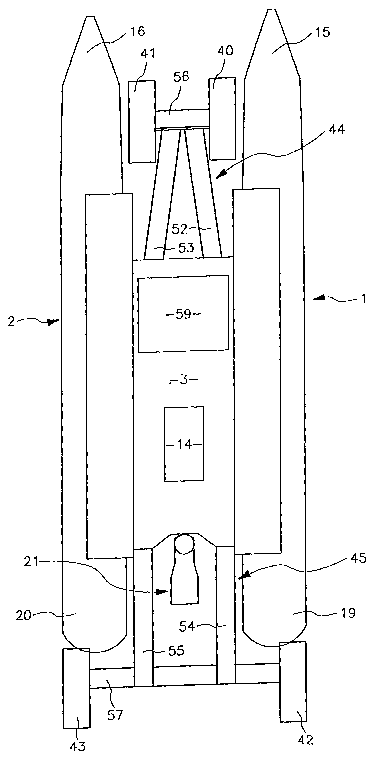
Subframes
Three land wheels, appropriately positioned, would be capable of supporting
the craft on land but there are preferably four for better stability. These
land
s wheels 40,41; 42,43 (Fig 8) are supported for rotation about their
substantially
horizontal axes on, and at, the extremities of sub-frames 44,45 which are able
to be moved, preferably independently, via height adjustment means 46, 47
(shown in Fig. 1 only), with respect to the framework 3, from a position,
where
the land wheels 40-43 stably support the catamaran for travel on land with the
to hulls clear of the land, and a position where at least the land wheels
associated with the front sub-frame, are raised upwardly beyond the bottoms
of the hulls and, usefully, to other positions as well. Preferably all land
wheels
are so raised. While the land wheels may be located inboard of the hulls,
extra
stability may be gained if at least one pair of them, perhaps the rear pair
42,43,
is are more or less in line with the hulls 1,2 but to the rear of them.
Balancing
factors may mean that the rear sections of the hulls may need to be deflated
to
get them out of the way when such land wheels are to be moved past the tails
19,20 as has been described with reference to Fig. 7.
2o The sub-frames 44,45 must be lowerable quite quickly, perhaps under
computer control, so that beaching is achieved speedily and accurately and
without needing to disengage the propeller, if that is the means of water
propulsion, to minimise the chance of a following wave swamping the craft and
13
CA 02431224 2003-06-06
WO 02/45978 PCT/NZO1/00271
also perhaps to maintain approach speed thus facilitating traverse over
difficult
land with limited tractionability.
There are many possible ways of providing the necessary sub-frame
movement but bearing in mind the desirability of having the sub-frames
completely clear of the water when the craft is floating and the land wheels
likewise, coupled with the need for there to be sufficient elevation of the
relatively long hulls necessary to give good performance on water, the best
option is to have two sub-frames 44,45 each pivoted to the framework 3.
to There would be one sub-frame 44 at the front and one sub-frame 45 at the
rear of the framework. Hydraulic or air-operated rams 50,51 (only shown in
Fig. 1) could be used to cause the sub-frames to be moved from an elevated
position in which they were substantially in a horizontal plane to a lowered
position in which they each pivoted about a substantially horizontal pivot
axis
is 48,49 (Fig. 1), carrying the land wheels downwardly with them. The angle of
pivoting arc could in theory be as much as about 90° to give maximum
elevation, but in practice a lesser angle will enable a more stable
arrangement;
for example the amount of movement about a pivot 48,49 could be about
55°.
2o It is important, to assist beaching in difficult conditions, that the full
weight of
the craft be transferable to the land wheels while the craft is still in
shallow
water. For example the bottoms of .the land wheels may be positioned to be
700mm below the bottoms of the hulls. If the hulls are thus completely or
14
CA 02431224 2003-06-06
WO 02/45978 PCT/NZO1/00271
mostly out of water then the land wheels get traction and the chance of a wave
overturning the craft is much reduced. The length of each sub-frame 44,45
may be about 1.6m and the land wheel, provided as a conventional wheel,
might have a diameter of about 1m.
The legs or arms 52,53; 54,55 (Fig. 8) of the sub-frames might conveniently be
provided in part by hollow tubes and suitable tubes might be aluminium mast
sections or preferably, for corrosion resistance, stainless steel. These could
be designed to provide air reservoir tanks and also hydraulic fluid reservoir
and
io cooling tanks. The ends of the tubes might in any case be sealed to
increase
overall flotation.
The front and rear sub-frames 44,45 are suitably hinged or pivoted on the
framework 3 for independent pivotal movement about substantially horizontal,
Is substantially parallel, axes 48,49 which are substantially perpendicular to
the
straight-ahead line of travel of the craft in use, and the height adjustment
means 46,47 may possibly include air rams (sometimes called bellows or
pneumatic actuators or springs) adjacent the hinge axis and powered by an
on-board compressor (not shown) driven by the motor 14. While pneumatic
2o bellows provide a useful amount of flotation compared with other options,
they
have limited travel and are single-acting and for those and for other reasons
double-acting hydraulic rams such as 50,51 are preferred. Hydraulic raising
and lowering is faster than pneumatics and it is important that the drag
created
Is
CA 02431224 2003-06-06
WO 02/45978 PCT/NZO1/00271
by the lowering of the sub-frames and associated land wheels be minimised in
order not to unduly slow the motion of the craft. Hydraulics allow fast
raising
and lowering and also allow a greater arc through which the sub-frames may
be swung. The improvement over pneumatics might be of the order of 25°.
The sub-frame legs or arms 52-55 might terminate in an axle or crossmember
such as 56,57 (Fig 8) which supports at each end an hydraulic motor (not
shown) driving an attached land wheel. kingpin assemblies (not shown) allow
for ram-actuated steering (not shown) of all the land wheels. When land
to speeds are low all may be steered, but when land speeds are to be higher
then the preferable rear steering ram or rams (not shown) might be locked,
with the land wheels in a straight-ahead position, to give increased stability
of
the craft, so at higher speeds on land steering is via the front land wheels
alone.
There might preferably be locking means (not shown) to mechanically, but
releasably, lock the sub-frames in selected positions to reduce stresses on
their operative hydraulic systems.
2o The preferable suspension system uses hydraulic raising and lowering of the
sub-frames 44,45 via double-acting hydraulic rams 50,51 with at least one
sealed-gas spring (not shown) for example of the kind used on CITROEN
[Trademark] cars. The hydraulic circuit (not shown) supplying the hydraulic
16
CA 02431224 2003-06-06
WO 02/45978 PCT/NZO1/00271
rams preferably includes multiple, sealed-gas springs (not shown) at least
some of which are selectable to enable choice of suspension firmness.
Access to and from the craft from both land and water is not very practicable
s over the sides. The sub-frames 44,45 might act as prime means of access to,
and egress from, the craft.
The rear sub-frame 45 may be provided with a stepped cover (not shown) so
that when the sub-frame is in the lowered position, whether on land or in the
to water, it can be used for access to the input station 59 or any deck of the
craft.
In many cases the rear sub-frame, with suitably strong hydraulics, might be
useful as a loading device to be lowered under some object to be loaded onto
or off the craft to help lift it out of, or lower it into, the water.
Otherwise with on-
board hydraulics an on-board crane (not shown) could easily be provided for
is some applications where it would be useful.
Where the sub-frame is suitably constructed it might be transformable to, or
useful as, extra temporary decking while not required for landing purposes.
2o The two spaced apart rear land wheels 42,43 supported on the rear sub-frame
45 have a track which preferably substantially equals the maximum width of
the craft across the hulls 1,2. This gives maximum stability while yet
facilitating
road travel.
17
CA 02431224 2003-06-06
WO 02/45978 PCT/NZO1/00271
There are two spaced apart front land wheels 40,41 supported on the front
sub-frame 44 (although there could be a single land wheel) and the track of
the
front land wheels is less than the minimum spacing between the hulls.
At the front, the sub-frame extremity terminates in the pair of land wheels on
a
short axle 56 such that the land wheels 40,41 lie in the space between the
hulls 1,2 with room for turning when steered, with a central axle pivot axis
(not
shown) running longitudinally to create a vehicle suspension of three points
to similar to that used on many agricultural tractors. A central nose cone 60
(shown only in Fig 4) might minimise any bow-wave created by a lowered axle
and land wheels and there might be a splash shield (not shown) on the
framework or front sub-frame to deflect any spray created by a lowered axle
and land wheels from any occupants of the craft.
Is
The hydraulic motors (not shown) for the land wheels might provide means of
braking the craft as well as driving it.
When such a craft is being beached the land wheels would preferably be
2o automatically lowered as the craft neared shore, utilizing a sensing device
(not
shown) adapted to cause lowering when the water floor-level was say 400mm
below the hulls but there needs to be a nice balance between the land wheels
making ground contact too early and having no traction, and making contact
is
CA 02431224 2003-06-06
WO 02/45978 PCT/NZO1/00271
too late when the hulls might get grounded and damaged. The front sub-frame
44 might be lowered before the rear sub-frame 45 if necessary to facilitate
landing.
s At the rear there might be an aerofoil (not shown) on the sub-frame, perhaps
forming a rear axle 57, the aerofoil being adapted to provide framework 3, and
thus hull, lift when the rear sub-frame 45 is lowered into water while there
is
forward motion of the craft.
to Also rear rams (such as 18 in Fig 7) can be adapted to deflect the sterns
or
tails 19,20 of the hulls downwards which will provide framework lift by virtue
of
the craft's motion forward. Such a mechanism might conversely provide tail
lift
to reduce the planing surface and increase on-water speed. Variation side to
side could enable a trim-tab like function to counter forces in reaction to
is propeller torque, uneven loading, wind forces or fast-turning forces.
An option is to have quite large diameter land wheels of conventional wheel
type - perhaps up to 1 m diameter. In order to avoid lengthening the
framework or the rear sub-frame 45, the section of each hull at the tails
19,20
2o is selectively deflated when beaching or un-beaching the craft, and maybe
for
road travel at speed and curled by means of a multistage hydraulic ram (such
as 18) in a radius tight enough for such a large land wheel to pass around it
19
CA 02431224 2003-06-06
WO 02/45978 PCT/NZO1/00271
(as shown in Fig 7 to some extent). This could apply to both the bow and stern
sections of the hulls depending on track width.
An advantage of deflating the tail of each hull during beaching is that this
s raises the front of the craft and assists beaching.
The height adjustment means 46,47 thus preferably enables each sub-frame
44,45 to be independently (if desired), positioned in at least 3 positions
namely:
to A fully raised position (as shown in Fig. 1 )
A fully lowered position (as shown in Fig. 2)
An intermediate position where the hulls clear land by substantially the
minimum amount needed for safe on-road travel (as shown in
Fig. 3).
Is
While only two sub-frames 44,45 have been described, more might be
provided. For example individual legs or arms 52-55 might form individual
sub-frames with each land wheel having its own sub-frame.
2o As an alternative to car-like steering on land the craft might be skid-
steered. In
that case the front land wheel or land wheels might be mounted on a
substantially vertical pivot for castor action while the rear land wheels
would be
able to be selectively braked and/or oppositely driven, independently. The
rear
CA 02431224 2003-06-06
WO 02/45978 PCT/NZO1/00271
land wheels could, as earlier defined, take the form of track assemblies (as
might the front) to reduce land pressure. It is even envisaged that the land
wheels could take the form of computer controlled feet for human-type walking
on the land surface.
Input station
An input station 59 is provided on the craft for any person who is to operate
the
craft on water or on land or both, and that person might be required to
exercise
judgement as far as lowering or raising of the land wheels was concerned
to during launching or retrieval of the craft if that function was not
automated. It
is, of course, possible that there may be no person on the craft at any time,
in
which case the input station would be occupied by a receiver (not shown) to
receive remote control signals or there could be a combination of such. The
input station may include a simple stand-up steering position or a fully
is enclosed cabin.
At the input station there would be all the necessary controls (not shown) for
operating the craft and preferably a computer (not shown) to automate some
functions.
Motor
The major ultimate power to effect movement on the craft comes from
hydraulic motors or rams. These are preferably driven from a pair of series
21
CA 02431224 2003-06-06
WO 02/45978 PCT/NZO1/00271
mounted hydraulic pumps (not shown) directly coupled to the output shaft of
the turbo-diesel motor 14 which would be about 150 to 200HP (110-150kW).
The diesel motor would also preferably operate a generator (not shown) to
provide an electrical energy supply and also an air compressor (not shown)
providing air at high pressure such as might be needed for operating power
tools such as jacks or spreaders to free trapped people who might be held in
the wreckage of a downed aircraft etc.
to Summary
The advantages of the above-mentioned construction are that the hulls 1,2 are
securely fixed to the framework 3 and no compromise needs to be made in
that respect. This leads to a construction which has the required strength to
resist forces which can be encountered when the craft is on the water, which
of
is course is extremely important for the safety of any occupant or occupants.
It is envisaged that some versions of the craft would not travel at any great
speed on land. Perhaps speeds of up to about 40kph might be practicable.
The objective would be to have enough land-going capability to enable the
2o craft to be moved to a suitable storage area on land - perhaps the owner's
house, if nearby. On-water speeds of about 20 knots or more are desirable.
Military objectives might be different.
22
CA 02431224 2003-06-06
WO 02/45978 PCT/NZO1/00271
When used as a rescue vehicle, a deck, if provided on the framework 3, could
enable a number of rescue pods (not shown) to be carried and quickly
deployed to persons who might be in the water so that a number of people
could be offered suitable support as quickly as possible.
23