Note: Descriptions are shown in the official language in which they were submitted.
CA 02432224 2004-03-15
76186-40
IMPROVED HYDROGEN AND CARBON DIOXIDE COPRODUCTION
Field of T6e Invention
The field of the invention is concurrent hydrogen and carbon dioxide
production.
Background of The Invention
Complex mixtures of gases such as refinery gases or offgases from combustion
processes are frequently employed as starting materials in the production of
purified gases,
and various systems have been developed to concurrently isolate at least 2 or
more gases at a
relatively high purity (i.e., greater than 90% (v/v)) from a single gas
mixture.
Some systems employ a serial configuration of PSA units, wherein a first PSA
unit
has a different selectivity from a second PSA unit; and wherein the offgas
from the first unit
is directed to the feed end of the second PSA unit. An example for this
configuration is
described by R. Kumar in U.S.Pat. No. 4,913,709. Kumar s serial configuration
of PSA units
with beds having non-identical adsorption specificity is favorable in cases
where relatively
TS high volumes of offgas are to be purified at a time. However, the
complexity and number of
coordinated cycle steps generally increases due to the different physico-
chemical properties
of the adsorbent beds, thereby adversely increasing cost and maintenance
requirements.
Other systems utilize configurations with a PSA unit and a non-PSA unit as for
example described in U.S.Pat. No. 4,553,981 to Fuderer. In Fuderer's system,
carbon dioxide
is removed as a waste gas from a feed gas stream by a COZ scrubber, and the
COZ-depleted
stream is subsequently fed into a HZ-PSA unit. The HZ-PSA offgas is then
vented via a waste
line into the atmosphere, or recycled to a converter or shift unit. While
concurrently
separating H~ and CO~ from the feed gas, Fuderer's configuration
advantageously may be
employed to reduce undesirable build-up of nitrogen and/or argon in the waste
gases from the
scrubber and H~-PSA unit by recycling the waste gases to the reformer or shift
converter.
However, considerable amounts of carbon dioxide and hydrogen remain in the
recycling
circuit and are typically vented or combusted, rendering them no more amenable
to recovery.
CA 02432224 2004-03-15
76186-40
-2-
Still other systems employ selective membranes to separate a desirable gaseous
component from the offgas of a PSA unit. For example, G. Intille describes in
U.S.Pat .No.
4,229,188 the use of hydrogen permeable membranes to recover HZ from the
offgas of a PSA
unit. Intille's membranes advantageously remove H2 with high selectivity in a
single process
step, however, the use of such membranes generally requires relatively high
pressure, thereby
increasing the overall energy demand. To avoid at least some of the problems
associated with
hydrogen-permeable membranes, Anand et al. teach in U.S. Pat. No. 5,435,836
the use of an
adsorbent membrane. Adsorbent membranes typically allow hydrogen recovery at
comparably
low pressure with relatively high specificity. The advantage of relatively low
pressure,
however, tends to be offset by the need of membrane exchange, thereby either
increasing the
complexity of the hydrogen plant, or necessitating discontinuous operation.
Thus, although various systems for concurrent production of desirable gases
from gas
mixtures are known in the art, all or almost aD of them suffer from one or
more than one
disadvantage. Therefore, there is a need to provide improved methods and
apparatus for
concurrent production of desirable gases from gas mixtures.
Summary of the Invention
The present invention is directed to a gas production plant comprising a gas
source, a
first and second separator, and a liquefying unit. The first separator
receives feed gas from the
gas source and produces a first offgas stream and a first product stream,
whereas the second
separator receives the first offgas stream to produce a second offgas stream
and a second
product stream. The liquefaction unit receives the first product stream and
the second offgas
stream thereby producing a liquefied third product stream and a third offgas
stream, and at
Least part of the third offgas stream is combined with the first offgas
stream.
CA 02432224 2004-03-15
76186-40
- 2a -
In a specific plant aspect, the invention provides
a gas production plant comprising: a gas source providing a
feed gas stream having a first gaseous component and a
second gaseous component; a first separator fluidly coupled
to the gas source, wherein the first separator removes at
least part of the first gaseous component from the feed gas
stream, thereby producing a first offgas stream and a first
product stream predominantly comprising the first gaseous
component; a second separator fluidly coupled to the first
separator, wherein the second separator removes at least
part of the second gaseous component from the first offgas
stream, thereby producing a second offgas stream and a
second product stream predominantly comprising the second
gaseous component; a liquefaction unit fluidly coupled to
the first and second separator, wherein the liquefaction
unit receives at least part of the first product stream and
at least part of the second offgas stream to produce a third
product stream predominantly comprising liquefied first
gaseous component; and wherein the liquefaction unit
produces a third offgas stream of which a first portion is
combined with the first offgas stream, and of which a second
portion is used as a non-waste gas.
In a method aspect, the invention provides a
method of removing a first gaseous component and a second
gaseous component from a feed gas, comprising: providing a
feed gas stream having a first gaseous component and a
second gaseous component to a first separator; removing at
least part of the first gaseous component from the feed gas
stream in the first separator, thereby producing a first
offgas stream and a first product stream predominantly
comprising the first gaseous component; fluidly coupling a
second separator to the first separator, wherein the second
76186-40
CA 02432224 2004-03-15
- 2b -
separator removes at least part of the second gaseous
component from the first offgas stream, thereby producing a
second offgas stream and a second product stream
predominantly comprising the second gaseous component;
fluidly coupling a liquefaction unit to the first and second
separators, wherein the liquefaction unit receives at least
part of the first product stream and at least part of the
second offgas stream to produce a third product stream
predominantly comprising liquefied first gaseous component;
and wherein the liquefaction unit produces a third offgas
stream of which a first portion is combined with the first
offgas stream, and of which a second portion is used as a
non-waste gas.
In one aspect of the inventive subject matter, the
gas source provides a feed gas predominantly comprising
hydrogen and carbon dioxide, which is produced from natural
gas via a steam reformer process. While the first separator
preferably comprises a C02 scrubber, the second separator
comprises a hydrogen pressure swing adsorption (PSA) unit,
and the liquefaction unit comprises in a particularly
preferred aspect an autorefrigeration unit.
CA 02432224 2006-04-12
76186-40
-3-
In another aspect of the inventive subject matter, a method of removing a
first gaseous
component and a second gaseous component from a feed gas employs a PSA unit
that
produces a first product stream predominantly comprising the second gaseous
component,
and a first offgas stream predominantly comprising the first gaseous component
and the
second gaseous component. At least part of the offgas stream is fed into a
liquefaction unit
that produces a second product stream and a second offgas stream, and at least
part of the
second offgas stream is recycled into the PSA unit.
Various features, aspects and advantages of the present invention will become
more apparent from the following detailed description of preferred embodiments
of the
I 0 invention, along with the accompanying drawing.
~riei' Description of The Drawing
Figure I is a schematic of a gas production plant according to the inventive
subject
matter.
Figure 2 is a flow diagram depicting a method of increasing recovery of a
gaseous
component from a feed gas according to the inventive subject .matter.
~Detailed~escri,ption
As used herein, the term "non-waste gas" refers to a gas that is used in a
process other
than venting into the atmosphere, and preferred processes include combustion
in a steam
reformer or gas turbine, expansion or compression, and heating/cooling in a
heat exchange
device.
As also used herein, the term "autorefrigeration system" refers to a device
that
produces high purity liquid COz using COZ as a refrigerant. An especially
contemplated
autorefrigeration ,system is described in wo 9 9 / 3 5 4 5 5 t o s . Reddy.
As further used herein the terms "HZ PSA unit" and "hydrogen PSA unit" both
refer to
a PSA unit that is configured to produce a product gas stream predominantly
comprising
CA 02432224 2004-03-15
76186-40
-4-
hydrogen. Similarly, a "C02 PSA unit" and a "carbon dioxide PSA unit" refer to
a PSA unit
that is configured to produce a product gas stream predominantly comprising
carbon dioxide,
wherein the term "predominantly comprising" means that the product gas stream
comprises at
least 50% of the carbon dioxide, hydrogen, or other compound that is
predominantly present
in a product.
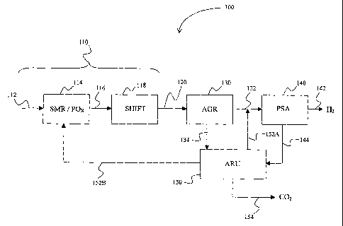
In Figure 1, a plant 100 generally has a gas source 110, in which a stream of
source
gas 112 is reformed in a reformer 114, and transferred via transfer line 116
to converter 118,
in which the reformed source gas is converted to yield feed gas stream 120. A
first separator
130 removes a first gaseous component from the feed gas to produce a first
product stream
134 and a first offgas stream 132. The first offgas stream 132 is fed into a
second separator
140 to produce a second product stream 142 and a second offgas stream 144.
Both second
offgas stream 144 and first product stream 134 are fed into liquefaction unit
150, and third
product stream 154 removes liquefied product from the liquefaction unit. A
first portion 152A
of a third offgas stream leaving the liquefaction unit is combined with the
first offgas stream
132, and a second portion 152B of the third offgas stream is combusted in the
reformer
burner.
In a preferred aspect of the inventive subject matter, the production plant is
a plant for
hydrogen and carbon dioxide coproduction, wherein the first gaseous component
is carbon
dioxide and the second gaseous component is hydrogen. The gas source comprises
a steam
reformer and a shift converter to convert a stream of natural gas
predominantly comprising
CH4 into a feed gas stream predominantly comprising COZ and H2. The first
separator is a
COa scrubber in combination with a flash unit and separation tank that removes
a first portion
of C02 from the feed gas, thereby producing a first product stream with a C02
concentration
of greater than 80mo1%, and a first offgas stream, which is fed into a
hydrogen PSA unit. The
second separator is a hydrogen PSA unit that produces a second product stream
containing H2
with a purity of greater than 99mo1%, and a second offgas stream containing
about 20mo1%
H2 and greater than 70mo1% C02. Both the first product stream 134 and the
second offgas
stream 144 are fed into autorefrigeration unit 150, which produces a third
product sh~eam 154
containing C02 with a purity of greater than 98moI%. Approximately 70% (by
voL) of the
CA 02432224 2003-06-18
WO 02/068084 PCT/USO1/49191
-S-
third offgas stream (i. e., first portion of the third offgas stream) is
admixed to the first offgas
stream, while about 30% (by vol.) is transferred to the steam reformer burner
(i.e., second
portion of the third offgas stream).
With respect to the configuration of the liquefaction uW t, it should be
especially
appreciated that increased rates of COZ and H2 recovery are achieved by (a)
feeding the H2-
PSA offgas to the autorefrigeration unit and (b) concurrent recycling of the
autorefrigeration
unit offgas into the HZ-PSA. For example, COZ that has not been removed from
the feed gas
stream in the first separator will be fed together with HZ into the
autorefrigeration unit via the
second offgas stream from the H2-PSA unit. The C02 in the second offgas stream
is
cryogenically recovered from the second offgas stream in the autoxefrigeration
unit, rendering
the autorefrigeration unit a secondary separator. The H2 in the second offgas
stream passes
through the autorefrigeration unit, and by re-feeding at least part of the
third offgas stream to
the H2-PSA, H2 from the second offgas stream is recycled to and subsequently
recovered by
the Ha-PSA unit.
1 S It should also be appreciated that in alternative aspects of the inventive
subject matter,
the gas source need not be limited to a gas source comprising a steam reformer
and a shift
converter, but may include various other components, the choice of which
mainly depends on
the desired gas. For example, where hydrogen production is particularly
desired appropriate
gas sources may employ components for partial oxidation of various
hydrocarbons, or coal
gasification. On the other hand, the gas source need not be restricted to a
source producing
predominantly hydrogen, and may include sources producing N2, CO2, CO, He, Ar,
etc. It is
still further contemplated that, where relatively pure gases are side products
of an industrial
process, appropriate gas sources may also comprise elements that are employed
in gas
purification rather than production, such as PSA units, absorber units,
distillation columns,
2S acid gas removal units, etc.
Consequently, the feed gas stream need not be restricted to a gas mixture
predominantly comprising HZ, and CO2. Alternative feed gas streams -are
contemplated to
include gas mixtures comprising Ca-C6 hydrocarbons, and higher, which may or
may not be
aliphatic, inert gases such as N2, He, Ar, or pre-treated gas mixtures that
have been enriched
CA 02432224 2003-06-18
with, or depleted of one or more compounds, For example, contemplated feed gas
streams
may comprise an effluent gas from a steam reforming process, a partial
oxidation process, a
stripping process, a combustion, or a coal gasification process.
With respect to the first separator it is preferred that appropriate first
separators
include an acid gas removal unitt, and particularly contemplated acid gas
removal units
employ a solvent that removes at least part of the rust gaseous component.
Depending on the
particular gaseous component and configuration of the separator, the solvent
may include
physical and chemical solvents, and preferred solvents are monoethanolamine,
activated
methyl-diethanolamine, propylene glycol, and glycol dirnethylether. Although
preferred first
separators include a C02 scrubber in combination with a flash unit and
separation tank,
various alternative separators are also contemplated. For example, where
relatively small
volumes of feed gases are processed, alternative first separators may include
selective
membranes. In other cases, where the feed gas is derived from a cryogenic
process, a
distillation apparatus may be utilized as the first separator, and fox
processes where recovery
of a gaseous component in high purity (e.g., greater than 99% (vlv)) is
desired, a pressure
swing adsorption unit may be employed as a first separator. Similarly, the
second separator
need not be limited to a hydrogen PSA unit, and alternative second separators
may include a
C02-PSA unit, a selective membrane, a distillation apparatus, etc., so long as
alternative
second separators are fluidly coupled to a first separator and receive at
least part of the first
offgas stream.
Although preferred liquefaction unit is a carbon dioxide autorefrigeration
unit,
contemplated alternative liquefaction units also include liquefaction units
with processes
requiring an external refrigerant such as ammonia, fluorohydrocarbons, or
fluorochlorohydrocarbons. The liquefied COZ obtained from the
autorefrigeration unit
preferably has a purity of greater than 98% (v/v), mare preferably greater
than 99% (v/v), and
most preferably greater than 99.9% (v/v). With respect to the amount/fraction
of the third
offgas stream that is admixed to the first offgas stream, it is contemplated
that while about
70% (by vol.) are preferable, many other anaounts/fractians are also
appropriate so long as at
least part of the third offgas stream is recycled to the second separator.
Generally
4iSt~i~tlll'1~P1 ~'~P~~"1"
CA 02432224 2003-06-18
7
contemplated amounts/fractions range between 0.1% and 100%, and more preferred
amounts/fractions are between 40% and 80%. For example, where the third offgas
stream
comprises only minor quantities of hydrogen, and the second separator is a H2-
PSA unit,
amounts of about 5-25% may be recycled to the first offgas stream. On the
other hand, during
normal operation of a HZ-PSA unit the second offgas stream will contain about
20% (v/v)
hydrogen, which may be almost completely recovered by recycling 70-90% (v/v)
or more of
the third offgas stream to the first offgas stream. Still further, it should
be appreciated that
admixing of the first portion of the third offgas stream to the first offgas
stream may be a
continuous process or a discontinuous process. For example, in some cases 80%
of the third
offgas stream may continuously be admixed to the first offgas stream, while in
other cases
100% of the third offgas stream may be admixed to the first offgas stream for
SOs in a 60s
interval.
Likewise, the amount/fraction of the second portion of the third offgas stream
may be
different from a preferred amount/fraction, and typically depends on the
amount/fraction of
the first portion of the third offgas stream. With respect to the use of the
second portion of the
third offgas stream, it is contemplated that various uses other than
combustion in a steam
reformer burner are also appropriate, so long as the second portion of the
third offgas stream
is utilized as a non-waste gas. For example, where the second portion of the
third offgas
stream has a relatively low temperature, the second portion could be employed
as a coolant,
or where the amount of combustible components {e.g., methane) is relatively
high, the second
portion may be combusted in a gas turbine. It should be especially appreciated
that due to the
configuration of the first and second separator in cooperation with the
liquefaction unit, the
concentration of the first and second gaseous components are preferably below
10% (v/v),
more preferably below 1 % (v/v), and most preferably below 0.1 % (v/v).
In Figure 2, a general method 200 of removing a first and a second gaseous
component from a feed gas has a step 210 in which a PSA unit is provided that
removes at
least part of the second gaseous component from the feed gas, thereby
producing a first
product stream predominantly comprising the second gaseous component, and a
first offgas
stream predominantly comprising the first gaseous component and the second
gaseous
. nrwlf'!~n SHEET
CA 02432224 2003-06-18
WO 02/068084 PCT/USO1/49191
_g_
component. In a further step 220, at least part of the first offgas stream is
fed into a
liquefaction unit that removes at least part of the first gaseous component,
thereby producing
a second product stream and a second offgas stream, and in a still further
step 230, at least
part of the second offgas stream is recycled into the PSA unit.
In a preferred aspect of the inventive subject matter, the first and second
gaseous
components are carbon dioxide and hydrogen, respectively, and the feed gas
(predominantly
comprising HZ and C02) is obtained from natural gas via steam reforming and
processing in a
shift converter. The PSA unit is a H2-PSA unit that produces a first product
stream
predominantly comprising HZ, and an offgas stream predominantly comprising HZ
and CO2.
The PSA offgas is fed into a carbon dioxide autorefrigeration unit, which
removes C02 from
the offgas by liquefaction, thereby producing a liquefied carbon dioxide
product stream.
About 70% (v/v) of the COZ-depleted offgas from the autorefrigeration unit is
recycled into
the feed end of the PSA unit.
It should be especially appreciated that the method according to the inventive
subject
matter confers various advantages to a method of removing a first and second
gaseous
component from a feed gas. For example, by feeding the offgas from a H2-PSA
unit into a
carbon dioxide autorefrigeration unit, remaining carbon dioxide from the feed
gas is
effectively recovered. Furthermore, the immediate recycling of at least part
of the offgas from
the autorefrigeration unit to the H2-PSA unit significantly reduces loss of
hydrogen as waste
J
gas. Thus, contemplated methods effectively increase the recovery of first and
second gaseous
component from a feed gas.
With respect to corresponding elements between method 200 and gas production
plant
100, the same -considerations apply for elements in methods 200 as discussed
in plant 100
(vide supra).
Thus, specific embodiments and applications of methods and apparatus for
improved
concurrent hydrogen and carbon dioxide production have been disclosed. It
should be
apparent, however, to those skilled in the art that many more modifications
besides those
already described are possible without departing from the inventive concepts
herein. The
CA 02432224 2004-03-15
76186-40
-9-
inventive subject matter, therefore, is not to be restricted except in the
spirit of the appended
claims. Moreover, in interpreting both the specification and the claims, all
terms should be
interpreted in the broadest possible manner consistent with the context. In
particular, the
terms "comprises" and "comprising" should be interpreted as referring to
elements,
components, or steps in a non-exclusive manner, indicating that the referenced
elements,
components, or steps may be present, or utilized, or combined with other
elements,
components, or steps that are not expressly referenced.