Language selection

Search

Patent 2432352 Summary

Third-party information liability

Some of the information on this Web page has been provided by external sources. The Government of Canada is not responsible for the accuracy, reliability or currency of the information supplied by external sources. Users wishing to rely upon this information should consult directly with the source of the information. Content provided by external sources is not subject to official languages, privacy and accessibility requirements.

Claims and Abstract availability

Any discrepancies in the text and image of the Claims and Abstract are due to differing posting times. Text of the Claims and Abstract are posted:

  • At the time the application is open to public inspection;
  • At the time of issue of the patent (grant).
(12) Patent Application: (11) CA 2432352
(54) English Title: QUICK MOUNT LIGHTING ASSEMBLY FOR CEILING FANS
(54) French Title: LUMINAIRE A INSTALLATION RAPIDE POUR VENTILATEURS DE PLAFOND
Status: Deemed Abandoned and Beyond the Period of Reinstatement - Pending Response to Notice of Disregarded Communication
Bibliographic Data
(51) International Patent Classification (IPC):
  • F21V 21/03 (2006.01)
  • F04D 25/08 (2006.01)
  • F04D 29/64 (2006.01)
  • F21V 33/00 (2006.01)
(72) Inventors :
  • PEARCE, RICHARD A. (United States of America)
(73) Owners :
  • HUNTER FAN COMPANY
(71) Applicants :
  • HUNTER FAN COMPANY (United States of America)
(74) Agent: FINLAYSON & SINGLEHURST
(74) Associate agent:
(45) Issued:
(22) Filed Date: 2003-06-13
(41) Open to Public Inspection: 2003-12-14
Examination requested: 2008-05-22
Availability of licence: N/A
Dedicated to the Public: N/A
(25) Language of filing: English

Patent Cooperation Treaty (PCT): No

(30) Application Priority Data:
Application No. Country/Territory Date
10/173,232 (United States of America) 2002-06-14

Abstracts

English Abstract


A ceiling fan having a set of fan blades rotatably
coupled with an electric motor housed within a motor
housing, a switch housing mounted below said set of fan
blades, a plurality of spring clips of an electric socket
in an array about a threaded mounting channel, a light kit
having an electric plug with a plurality of terminal blades
sized and arranged about a central plug passageway to be
plugged into said switch housing socket spring clips, and
a bolt sized to be passed through said light kit electric
plug passageway and threaded into said switch housing
threaded channel in mounting the light kit beneath the
switch housing.


Claims

Note: Claims are shown in the official language in which they were submitted.

-6-
WHAT IS CLAIMED IS:
1. A quick mount lighting assembly for a ceiling fan that
has a switch housing that houses an electrical connector
electrically connectable to a municipal power source and a
threaded mechanical connector, and with said quick mount lighting
assembly comprising a light kit housing with a bottom opening
that may be positioned adjacent the ceiling fan switch housing
with said housing opening providing external access to the switch
housing mechanical connector, an electric connector mounted in
said light kit housing electrically connected to at least one
lamp socket, and a knob with a threaded shank sized to be passed
through said light kit housing opening and threaded onto the
switch housing threaded mechanical connector, whereby the
lighting assembly may be quickly mounted to the ceiling fan by
placing the light kit housing adjacent the fan switch housing
with the light kit electrical connector connected with the switch
housing electrical connector and with the knob shank passed
through the light kit housing opening and threaded into the light
switch mechanical connector.
2. The lighting assembly of claim 1 wherein said light kit
housing is generally dish shaped.
3. The lighting assembly of claim 1 wherein the fan switch
housing electrical connector is an electric socket and wherein
said light kit electrical connector is an electric plug.
4. The lighting assembly of claim 1 wherein the fan switch
housing threaded mechanical connector has internal screws threads
and wherein said threaded knob has external screw threads.

-7-
5. The lighting assembly of claim 1 wherein the fan switch
housing electric connector is an electric socket having an array
of electric connectors located about said switch housing
mechanical connector, and wherein said light kit electric
connector is an electric plug having an array of blade terminals
located about said light kit mechanical connector.
6. A ceiling fan having a set of fan blades rotatably
coupled with an electric motor housed within a motor housing, a
switch housing mounted below said set of fan blades, a plurality
of spring clips of an electric socket in an array about a
threaded mounting channel, a light kit having an electric plug
with a plurality of terminal blades sized and arranged about a
central plug passageway to be plugged into said switch housing
socket spring clips, and a bolt sized to be passed through said
light kit electric plug passageway and threaded into said switch
housing threaded channel in mounting the light kit beneath the
switch housing.

Description

Note: Descriptions are shown in the official language in which they were submitted.


CA 02432352 2003-06-13
-2_
10 QUICK MOUNT LIGHTING ASSEMBLY FOR CEILING FANS
TECHNICAL FIELD
This invention relates generally to electrically
powered ceiling fans, and more specify:tally to ceiling fans
that have one or more lamps.
BACKGROUND OF THE INVENTION
Electrically powered ceiling fans often have a lamp or
several lamps located beneath the fan blades and their
orbital path of travel. Fan manufacturers have designed
such fans so that light kits of different shapes and
styles, and with different numbers of lamps, may be
selected by the consumer at retail and mounted to the fan
body during fan installation. The light kit is mounted to
the fan only after the fan itself has been mourited to the
ceiling and its switch housing wired to the building wiring
in the ceiling as through a tubular down rod. Power to
both the fan motor and fan lamp is thus run through the
swatch housing.

- CA 02432352 2003-06-13
-2-
~-Ieretofore light kits have been mounted to 'the fan
following fan installation by connecting its wires to
wires within the switch housing as with insulated
connecters or tape. Mechanical connection has then been
made with screws passed through holes in the sides of the
light kit and the switch housing while taking care that the
wiring remains bundled properly within both the switch
housing and light kit. This has all had to be done by the
installer while working overhead on a ladder from below.
Often the installer, at least of the light kit itself, is
the consumer itself rather than a professional electrician.
The task of light kit installation thus has proven to be
rather difficult, tedious, and slow. Furthermore, once the
light kit is installed it is difficult to change the light
kit to another design.
Accordingly, it is seen that a need has long existed
for a ceiling light kit that could be more easily and
quickly mounted a fan. It thus is to the provision of such
that the present invention is primarily directed.
S~dARY ~F THE INVI:N'~ION
In a preferred form of the invention a quick mount
lighting assembly is provided for a ceiling fan that has a
switch housing that houses an electrical connector
electrically connectable to a municipal power source and a
threaded mechanical connector. The quick mount lighting
assembly comprises ~a light kit hous~.nc~ with a bottom
opening that may be positioned adjacent the ceiling fan
switch housing with the housing opening providing external
access to a switch housing mechanical connector. An
electric connector is mounted in the light kit housing
electrically connected to at least one Lamp socket
supported on the kit housing. The assembly also has a knob
with a threaded shank sized to be passed through the light
kit housing opening and threaded onto the switch housing
mechanical connector. So constructed, the lighting

CA 02432352 2003-06-13
-3-
assembly may be quickly mounted to the ceiling fan by
placing the Light kit housing adjacent to or against the
fan switch housing with the light kit electrical connector
connected with the switch housing electrical connector and
with the knob shank passed through the light kit housing
opening and threaded into the light switch mechanical
connector.
In another preferred form of the invention a ceiling
fan having a set of fan blades rotatably coupled with an
electric motor housed within a motor housing, a switch
housing mounted below the fan.blades and a plurality of
spring clips of an electric socket in ~n array about a
threaded channel. The fan also has a light kit with an
electrical plug with terminal blades sized and arranged
~.5 about a central plug passageway to be plugged into the
switch housing socket spring clips. A bolt is provided
that is sized to be passed through the la_ght kit electric
plug passageway and threaded into the switch housing
threaded channel in mounting the light kit beneath the
switch housing.
BRIEF DESCRIPTION OF THE DRAWING
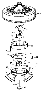
Fig. 1 is an exploded view, in perspective,. of a
ceiling fan and quick mount lighting assembly that embodies
the invention in its preferred form.
Fig. 2 is a side view, in cross-section, of the
ceiling fan switch housing and quick mount lighting
assembly shown positioned for mounting.
Fig. 3 is a side view; in cross-section, of the
ceiling fan switch housing with the lighting assembly shown
electrically and mechanically mounted thereto.

CA 02432352 2003-06-13
~~'° TA=~t~'~ ~~'J~R~~T~~~
Referring now in more detail to the drawing there is
shown a ceiling fan having a conventional fan motor housing
11. An unshown electric motor is housed within the housing
11 that rotates a set of unshown fan blades in an orbital
path of travel below the housing. The housing is mounted
to a downrod from a room ceiling through which electrical
wires extend from the motor to a source of municipal power
via a fan switch.
1.0 A fan switch housing 13 is conventionally mounted
beneath the motor housing which houses a fan power switch
14 that may be manually operated by a pull chain 15. A
socket 17 with spring clip electric terminals 18 is also
mounted in the switch housing I3 by a mounting bracket 20
and threaded nipple 21 by screws 23. Electric wiring 19
extends from the socket to the switch 14 where the switch
14 controls both the fan and fan lights. The socket has a
central passage therethrough with a tapered wall 22.
A light kit 25 is shown mounted below the motor
housing Z1. It has an open top dish shaped housing 26 with
an annular rim 27 to which lamp sockets 28 are mounted to
receive unshown light bulbs. These are connected by wires
29 to a plug 30 that is mounted to the kit housing 26
beneath an isolator 32. The plug has three electric blade
terminals 34 mounted in an array about a centering tube 35
that is threaded through a central. channel. through the plug
housing 36. Finally, the lighting assembly has a knob 40
with a threaded shank 41.
To mount the light kit 25 to the fan switch housing l3
its housing 27 is simply raised upwardly from its position
shown in Fig. 2 to that shown in Fig. 3. In doing so the
plug terminal blades 34 enter the Socket spring clip
terminals 18 and the threaded shank 41 of the knob helps
engage the inside tapered wall 22 of the socket. As this
occurs the rim 27 of the Light kit becomes seated in an
annular recess of the switch housing. This establishes

CA 02432352 2003-06-13
-5-
electrical connection of the light kit with the fan switch
housing.
As electrical connection is being made the knob shank,
which has been loosely held to the light kit by a retainer
clip 44, has been guided by contact with the tapered socket
wall 22 into alignment with the threaded nipple 21 of the
socket mounting bracket 20.
The knob 40 is then used to mechanically secure the
light kit by threading its shank 41 into the internal
threads of the bracket nipple 21. This is continued until
the knob itself has been brought flush against the bottom
of the light kit housing. Should it later. be desirable to
remove the light kit the knob 40 is simply unthreaded and
the kit plug pulled out of the socket.
It should be understood that once the light kit is
mounted it may be removed and replaced by a light kit of
another design. As such, lights kids may be quickly and
easily changed, a feature that would enable a consumer to
change light kits for special occasions or events such as
birthdays and holidays.
It thus is seen that a lighting assembly is now
provided for a ceiling fan that may be mounted and
dismounted quickly and with ease. Though the mechanical
mount is achieved with a hand knob with threaded shank, the
knob itself could be replaced with a bolt, flange or other
like that flares outwardly from the shank to underlay the
light kit- housing. Other modifications, additions or
deletions may of course be made without departure from the
spirit and scope of the invention as set forth in the
following claims.

Representative Drawing
A single figure which represents the drawing illustrating the invention.
Administrative Status

2024-08-01:As part of the Next Generation Patents (NGP) transition, the Canadian Patents Database (CPD) now contains a more detailed Event History, which replicates the Event Log of our new back-office solution.

Please note that "Inactive:" events refers to events no longer in use in our new back-office solution.

For a clearer understanding of the status of the application/patent presented on this page, the site Disclaimer , as well as the definitions for Patent , Event History , Maintenance Fee  and Payment History  should be consulted.

Event History

Description Date
Application Not Reinstated by Deadline 2010-06-14
Time Limit for Reversal Expired 2010-06-14
Deemed Abandoned - Failure to Respond to Maintenance Fee Notice 2009-06-15
Letter Sent 2008-08-26
Request for Examination Received 2008-05-22
Request for Examination Requirements Determined Compliant 2008-05-22
All Requirements for Examination Determined Compliant 2008-05-22
Inactive: IPC from MCD 2006-03-12
Inactive: Cover page published 2003-12-14
Application Published (Open to Public Inspection) 2003-12-14
Inactive: IPC assigned 2003-08-13
Inactive: IPC assigned 2003-08-12
Inactive: First IPC assigned 2003-08-12
Application Received - Regular National 2003-07-22
Filing Requirements Determined Compliant 2003-07-22
Letter Sent 2003-07-22
Inactive: Filing certificate - No RFE (English) 2003-07-22

Abandonment History

Abandonment Date Reason Reinstatement Date
2009-06-15

Maintenance Fee

The last payment was received on 2008-05-26

Note : If the full payment has not been received on or before the date indicated, a further fee may be required which may be one of the following

  • the reinstatement fee;
  • the late payment fee; or
  • additional fee to reverse deemed expiry.

Please refer to the CIPO Patent Fees web page to see all current fee amounts.

Fee History

Fee Type Anniversary Year Due Date Paid Date
Application fee - standard 2003-06-13
Registration of a document 2003-06-13
MF (application, 2nd anniv.) - standard 02 2005-06-13 2005-05-27
MF (application, 3rd anniv.) - standard 03 2006-06-13 2006-06-05
MF (application, 4th anniv.) - standard 04 2007-06-13 2007-06-13
Request for examination - standard 2008-05-22
MF (application, 5th anniv.) - standard 05 2008-06-13 2008-05-26
Owners on Record

Note: Records showing the ownership history in alphabetical order.

Current Owners on Record
HUNTER FAN COMPANY
Past Owners on Record
RICHARD A. PEARCE
Past Owners that do not appear in the "Owners on Record" listing will appear in other documentation within the application.
Documents

To view selected files, please enter reCAPTCHA code :


To view images, click a link in the Document Description column. To download the documents, select one or more checkboxes in the first column and then click the "Download Selected in PDF format (Zip Archive)" or the "Download Selected as Single PDF" button.

List of published and non-published patent-specific documents on the CPD .

If you have any difficulty accessing content, you can call the Client Service Centre at 1-866-997-1936 or send them an e-mail at CIPO Client Service Centre.


Document
Description 
Date
(yyyy-mm-dd) 
Number of pages   Size of Image (KB) 
Abstract 2003-06-13 1 26
Description 2003-06-13 5 273
Drawings 2003-06-13 2 104
Claims 2003-06-13 2 89
Representative drawing 2003-08-12 1 11
Cover Page 2003-11-18 2 43
Courtesy - Certificate of registration (related document(s)) 2003-07-22 1 105
Filing Certificate (English) 2003-07-22 1 158
Reminder of maintenance fee due 2005-02-15 1 109
Reminder - Request for Examination 2008-02-14 1 119
Acknowledgement of Request for Examination 2008-08-26 1 176
Courtesy - Abandonment Letter (Maintenance Fee) 2009-08-10 1 174