Note: Descriptions are shown in the official language in which they were submitted.
CA 02432407 2003-06-18
WO 02/053085 PCT/USO1/50549
TITLE OF THE INVENTION
VIAL DISPENSER
BACKGROUND OF THE INVENTION
The present invention relates to an apparatus for storing and dispensing
vials. Generally, the vials of the invention may contain liquid or solid
compositions,
and more particularly the vials will contain pharmaceutical compositions. The
dispenser may be displayed in a suitable location for easy identification and
removal
of vials for use.
Physicians and nurses typically handle a plurality of vials of medicine,
saline and other pharmaceutical compositions daily. Usually these vials are
stored in
manufacturer's packaged container and Dept refrigerated, or the vials can be
stored
openly on a storage shelf. However, due to the variety of products typically
stored in
vials, clinicians and nurses require a dispensing apparatus that provide easy
access in
the selection and removal of particular vials when necessary.
The prior art contains a selection of devices fox storing and dispensing
a plurality of containers such as vials, bottles, cans, etc. Generally, the
containers are
of a similar size and shape. The composition within the containers may be
sorted
within the device according to color, flavor, concentration, variety, etc.
U.S. Patent No. 5,131,563, issued July 21, 1992 to Yablans, assigned
to Pop Display, Inc., teaches an article dispensing apparatus wherein
identical articles
are vertically aligned in a plurality of separate columns and held in contact
with one
another. Each column has a dispensing side and a storage side as well as upper
and
lower sides. The dispensing side of the column has upper and lower sides that
cooperate to retain an article until it is dislodged from the column by
lifting the lower
end and removing the article. One side of a spring coil is resiliently
attached to an
upper-dispensing side of the apparatus while the second side of the coil is
attached to
an article pushing assembly. The length of the coil is sufficiently long so
that the
pushing assembly can extend over the top of the column to the storage side of
the
apparatus. The coil can be extended so that the pushing assembly is behind the
last
article on the storage side of the apparatus. In operation, when one article
is removed
from the column, the spring coil retracts and causes the pushing assembly to
advance
the remaining articles towards the dispensing side of the column. The
resiliency in
the coil will continue to retract and move the articles towards the dispensing
side of
the column until all the articles are removed therefrom.
-1-
CA 02432407 2003-06-18
WO 02/053085 PCT/USO1/50549
U.S. Patent No. 5,240,124, issued August 31, 1993 to Kunz, assigned
to Decision Point Marketing, Inc., teaches a point of sale push device. The
device can
be characterized as having a slidably mounted pusher on parallel rails,
wherein the
rails have a dispensing side and a closed side. The first end of an resilient
Boil is
attached to the pusher and the second end of the coil is attached to the
dispensing side
of the rails to allow the pusher to slidably extend to the closed side of the
device. The
dispensing side of the device has a stop so that articles placed in the device
are held
there until lifted from the device. After an article is removed from the
device, the
resilient coil retracts the pusher towards the dispensing side of the device
to advance
the remaining articles.
U.S. Patent Nos. 5,743,428 and 5,649,363 to Rankin, VI, issued April
28, 1998 and May 5, 1998, respectively, assigned to Vulcan Spring &
Manufacturing
Co., teach an apparatus for dispensing items. Rankin, VI teaches a device
similar to
Yablans, however, the retractable spring coil is vertically mounted atop to
column.
The coil also has a consecutive numbering sequence printed thereon to coincide
to the
number of articles remaining in the column.
The foregoing prior art, while providing dispensing devices that
display and advance a plurality of articles for easy selection, it fails to
provide a
device suitable for dispensing vials containing pharmaceutical compositions. A
vial
dispensing device that provides a sufficient separation of the front most vial
from the
remaining vial for easy identification and selection is required. A device
that
maximizes space as well as placement of the vials in the dispenser is also
desired.
SUMMARY OF THE INVENTION
The present invention relates to an apparatus for storing and dispensing
a plurality of like pharmaceutical articles, comprising a plurality of
parallel aligned
columns for storing the articles, the articles characterized as a first
article, several
articles, and a rear article contacting one another, each column having a
bottom side
for holding articles and a front opening for dispensing the articles, the
first article
being adj acent to the front opening and the remaining articles being held in
the
column behind the first article, the articles in the column being biased from
the rear
article towards the first article by resilient spring means, the apparatus
further
comprising a tilt ramp attached to the front opening at a sufficient length
and
decreased angle to the bottom side of the column to provide space between the
first
and several articles allowing the first article to separate contact from the
several
-2-
CA 02432407 2003-06-18
WO 02/053085 PCT/USO1/50549
article for removal of the first article from the front opening, the next of
several
articles being biased toward the front opening by elastic means.
The invention further relates to a method for arranging several
dispensers having the tilt ramp to provide improved identification and
dispensing of
articles.
BRIEF DESCRIPTION OF THE DRAWINGS
Other novel features and advantages of the present invention will
become apparent from the following description when taken in conjunction with
the
accompanying drawings, in which:
FIG. 1 illustrates an oblique view in elevation of the vial dispenser of
the invention;
FIG. 2 illustrates an oblique view in elevation of the pusher of the
invention;
FIG. 3 illustrates an oblique view in elevation of a stack arrangement
of the dispenser of the invention;
FIG. 4a illustrates a side view in elevation of the vial dispenser of the
invention further illustrating the tilt ramp of the front opening; FIG. 4b
illustrates a
side view in elevation of the vial dispenser wherein the tilt ramp and the
column are
depicted as containing several vials. Push assembly a with spring coil are
shown
advancing vials in the dispenser.
FIG. 5 is a top view in elevation of the dispenser illustrating the
columns; and
FIG. 6 is a front view in elevation of the dispenser.
DETAILED DESCRIPTION OF THE INVENTION
It should be understood that while the apparatus of the present can be
used for storing and dispensing a plurality of like articles, a typical
embodiment of the
invention is suitable for storing and dispensing numerous pharmaceutical
-3-
CA 02432407 2003-06-18
WO 02/053085 PCT/USO1/50549
compositions, such as formulations, vaccines, serums, etc. While it will
become
obvious to those skilled in the art the numerous type of articles that axe
suitable for
storing and dispensing in the apparatus of the invention, typical articles are
pharmaceutical vials for vaccines, serums and the like. One preferred vial for
storage
and dispensing is known in the art as a 0.5 mm glass vial.
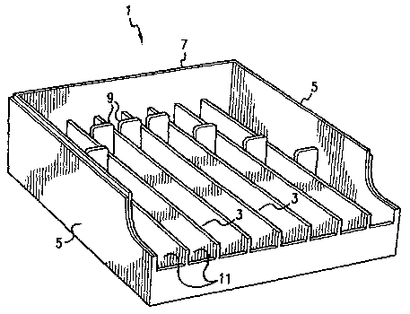
Referring to the drawings, FIG.1 illustrates an oblique view in
elevation of the dispenser of the invention, wherein the dispenser 1 may be
characterized as having a plurality horizontally, aligned columns 3 inside of
a base
having side walls 5 and back wall 7. A pushing assembly 9 is arranged
vertically to
the position and slidably attached in each column 3. The pushing assembly
slides the
length of column 9.
FIG. 2 illustrates an oblique view in elevation of the pushing assembly
9 of the invention. Generally, attached to pushing assembly 9 is a first end
of
resilient, elasticity means, the second end of the resilient means being
attached to
front opening 11. Typically, the resilient, elasticity means is a metal or
polymeric,
spring coil that rests behind pusher assembly 9. During operation, the
elasticity
means is stretched by sliding pushing assembly 9 from a rest position where it
abuts
front opening 11 to the end of column 3 abutting back wall 7. When articles,
e.g.
vials, are placed in column 3 between pusher assembly 9 and front opening 11,
the
elasticity means provides biasing by retracting from a stretched position,
thereby when
a front article is removed from the column, the elasticity means, by
contracting,
moves the remaining articles in the column towards front opening 11.
FIG. 3 illustrates an oblique view in elevation of the dispenser 1 in a
stack arrangement, wherein several dispensers are placed one atop another so
that the
front opening 11 of each dispenser is easily accessible for identification and
removal
of a vial from column 3 for administration to a patient.
FIG. 4a illustrates a side view in elevation of dispenser 1 further
illustrating tilt ramp 13 attached at front opening 11 of column 3. Tilt ramp
13 is
characterized as means for advancing the front most vial in column 3 to a
position
where the top of the vial, in a horizontal position, tilts away from back wall
7 of
dispenser 1 at an angle of from about 12° to about 1 ~°. Tilt
ramp 13 positions the
front vial away from the remaining vials for easy identification and removal
from the
apparatus. Attached at the bottom side of column 3 is ramp 15 having a length
of
about the diameter of a vials to be contained in the dispenser. Tilt ramp l3
is further
characterized as an attachment to the vertically arranged retaining wall 17,
wherein
-4-
CA 02432407 2003-06-18
WO 02/053085 PCT/USO1/50549
the height of the wall is sufficient to securely hold a vial therein.
Retaining wall 17 is
elevated downwardly, away from the vertical walls 5 and 7 of dispenser 1 at an
angle
of from about 12° to about 18°, so that the angle of ramp 15 and
wall 17 remain at an
angle of about 90°. Retaining wall 17 may conveniently have a pad
attached thereto
for absorbing shock resulting from the biasing of several vials in column 3.
As further illustrated in FIG. 4a, several dispensers 1 may be placed
atop each other for easy identification and selection of vials containing
different
compositions therein. Different arrangements of the vials in the dispensers,
different
number sequencing, color coding, etc., to assist one in readily identifying
like vials
containing different compositions will become apparent to those skilled in the
art. In
such an arrangement, a maximum of about five or six dispensers may be stacked
atop
each. Generally, the dispensers are arranged in a stair step fashion each
subsequent
dispenser in the stack is placed a measured distance away from the front
opening of
the dispenser underneath the next dispenser.
FIG. 4b illustrates a stacking arrangement of the dispensers wherein
vials are shown being advanced through a column by a push assemble 9, a spring
means 21 providing the force for moving the vials 18. The dispensers can be
stacked
is a 'stair step' fashion, wherein the upper dispenser slightly 'under hangs'
the lower
dispenser as shown in the figure.
FIG. 5 illustrates a top view in elevation of the dispenser of the
invention. A plurality of independently operated linear columns 3 are arranged
in a
parallel fashion. Exterior walls 5 and 7 define the outer boundaries of the
dispenser,
and front opening 11 is opposite back wall 7.
FIG. 6 illustrates a sectional view along B-B of FIG. 5, behind the tilt
ramp illustrates the location of the pusher assembly 9 in column 3. The pusher
assembly is slidably attached to tracks 19 for moving vials from back wall 7
in
column 9 to the front opening 11. The moving means typically provide biasing
movement for moving remaining vials forward and a next vial into tilt ramp 13
after
the front vial is withdrawn from the tilt ramp.
In a general embodiment of the invention, there is described a vial
dispensing apparatus particularly suitable for storing and dispensing vials
containing
pharmaceutical compositions. The dispenser can be described as an apparatus
for
storing and dispensing a plurality of like articles, the dispenser comprising
a plurality
of parallel, aligned columns for storing the articles, where the article is
preferable a
-5-
CA 02432407 2003-06-18
WO 02/053085 PCT/USO1/50549
vial. The vials can be characterized as a first vial, a rear vial, and several
vials there
between, wherein the vials are in contact with one another along the side
edges
thereof. Each column has of the dispenser has a bottom side for holding the
vials and
a front opening for dispensing the vials, the first vial is normally adjacent
to the front
opening of the dispenser, and the remaining vials are held in the column
behind the
first vial. The vials in the column are biased from the rear vial towards the
first vial
by resilient spring means. The biasing means operate to move a second vial to
the
front opening when the first vial is removed from the dispenser. The dispenser
further
comprising a tilt ramp attached to the front opening at a sufficient length
and
decreased angle to the bottom side of the column to provide space between the
first
and several vials allowing the first vial to separate contact along the side
edge from
the several vials, but remain in contact along the bottom end of the first and
second
vials, for removal of the first vial from the front opening, the next of
several vials
being biased toward the front opening by resilient spring means.
Tilt ramp 13 attached to the front opening of the dispenser provides a
mechanism wherein the first vial can be appropriately separated from the
remaining
vials in the column from removal from the dispenser by grasping with the hand
or
other suitable means. The vials, typically contacting one another along the
leading
and rear edges as they are aligned within the column, are separated except at
the
bottom end when the front vial rests in the tilt ramp. The tilt ramp can be
better
described as bottom ramp 15 and side ramp 17. The bottom and side ramps
cooperate
to provide an attachment to each column of the invention for the resting of
the
forward most vial in a column until it is removed therefrom. This mechanism
provides a stable resting place for vials in the column to be easily removed.
The angle
between bottom and side ramps 15 and 17, respectively, will generally be about
90°.
Optionally, a vertically standing wall at the front of the dispenser, as shown
in FIG.
4b can be used to support side ramp 17.
-6-