Note: Descriptions are shown in the official language in which they were submitted.
CA 02432563 2003-06-17
1A HJP-1O5X2C2 CANADA
DESCRIPTION
SEPTIC TANK KIT
Cross-Reference to Related At~plications
This application claims the benefit ofpatent application Serial No.
/0/439,024, filed
May 14, 2003, provisional patent application Serial No. 60/415,458, filed
October l, 2002
and provisional patent application Serial No. 60/450,974, filed February 28,
2003; all of
which are hereby incorporated by reference in their entirety.
Field of the Invention
The present invention relates generally to septic tanks, and more
particularly, to a
septic tank kit which can optionally be assembled at the site of installation.
Background of the Invention
Septic tanks are typically used at dwellings that are not connected to public
sewage
facilities. The septic tank is typically located underground and is basically
a batch sewage
processor. Sewage from the dwelling is sent to the septic tarrlc where it is
acted on by
microorganisms, where through biochemical reactions the sewage is decomposed.
Subsequently, liquid and gaseous effluent is discharged into the surrounding
soil. Solids
remaining in the tank are periodically cleaned. More information regarding
septic tanks can
be found in, for example, Woodson, R. Dodge: Builder's Guide to Wells and
Septic Systems,
McGraw Hill; and Burks, Bennette D. and Mary Margaret Minnis: Onsite
Wastewater
Treatment Systems, Hogarth House, Ltd. Both of these are incorporal:ed herein
by reference
to the extent they are not inconsistent with the following explicit teachings.
Prior art septic tanks are often made of concrete, glass fiber reinforced
resin
materials, or rotationally molded plastic materials. Because of the septic
tank size and
weight, they are typically transported to the work site by truck, and may
require a crane fox
placing into position.
S:1SH-APPSIhjp-I OSx2c2.canada.doc!DNB/srp
CA 02432563 2003-06-17
2 HJf-1O5X2C2 CANADA
>3rief summary of the Invention
The septic tank of the subject invention is available as a septic tank kit
which can be
assembled on site comprising, in a preferred embodiment, a tank lid, a tank
bottom, a pair of
opposing side walls, and a pair of opposing end walls having a tank flow
outlet and a tank
flow inlet, where a flange is affixed at the tank flow outlet and at the tank
flow inlet. The
tank lid preferably comprises a pair of lid openings, which are covered by
removable hatch
covers. The hatch covers preferably comprise a hatch handle for ease of
removal and in one
embodiment are removably affixed to the tank Iid with angle connection
brackets.
The septic tank is assembled using angle connection brackets, where the
brackets are
affixed to the tank lid, tank bottom, side walls, and end walls using;
fasteners such as, for
example, stainless steel cap screws. A silicone sealant can be interposed
between the tank
lid, tank bottom, side walls, end walls and the connection brackets, forming a
substantially
leak proof sealing gasket.
The septic tank kit further preferably comprises a baffle positioned within
the septic
tank to form two compartments: an inlet compartment ideally but not
necessarily
encompassing approximately 2/3 of the total volume of the tank, and an outlet
compartment.
The baffle presents a barner which enables the larger sediment to settle in
the inlet
compartment, with the remaining effluent flowing into the outlet compartment
through a
baffle port and/or over the top of the baffle if the baffle does not extend
completely from the
floor of the tank to the tank's ceiling.
To provide greater structural rigidity, the septic tank can comprise
structural support.
In embodiments with a baffle, the baffle extends upward from the bottom of the
tank and
from one side of the tank across to the other, thereby providing some
additional internal
horizontal support. If the baffle is an embodiment that extends upvrard
completely to the
tank's ceiling, then it also provides additional internal vertical support.
However in
embodiments without a baffle, even when a baffle is present, additional
internal support may
be desired. For example, the inlet compartment can comprise vertical and
horizontal
structural supports, where at least one vertical support member is interposed
between the
tank lid and the tank bottom, being connected to the tank bottom using, for
example, a flange
S:1SH-APPSIhjp-l OSx2c2.canada.doc/DNB/srp
CA 02432563 2003-06-17
3 HJP-1O5X2C2 CANADA
or collar. The inlet compartment can further comprise two or more horizontal
support
members, wherein at least one horizontal support is connected to and
interposed between the
side walls, and the at least one other horizontal support is connected to and
interposed
between the inlet end wall and the baffle. The vertical support can be affixed
to the
horizontal supports to provide greater stability.
The outlet compartment can optionally comprise at least one horizontal
support,
where the horizontal support is connected to and interposed between the outlet
end wall and
the baffle. Obviously, in view of the teachings herein, if vertical or other
horizontal supports
are desired in the outlet compartrraent, they are easily provided as will be
readily apparent to
the skilled artisan.
For ease of use and transportation to the work site, the septic tanks taught
herein are
available in an unassembled condition where they can then be assembled on the
work site.
Although not necessary, it is preferred that kits according to the subject
invention include
instructions for assembly into septic tanks.
This is the first teaching of using sheet plastic, or flat plastic panels, for
the
construction of septic tanks. Acceptable plastics include, but are not limited
to, such plastics
as homopolymer polypropylene (homopolymer) or copolymer polypropylene
(copolymer).
As will be readily apparent to the skilled artisan in view of the teachings
herein, any and all
plastics available as sheet stock (i.e., polyvinylchloride (PVC),
polyethylene, etc.) can be
used to practice the subject invention. It is also the first teaching of the
use of extrusion
welding in the manufacture of septic tanks. Extrusion welding is a well-known
technique
where an extruded plastic wire, (for example, 1/8" or 3/16" diameter
polypropylene) is
superheated, melting and effectively forming a caulk between two plastic
sheets or panels.
Superheated air from the tip of the welding gun also heats and melts the
panels and the bead
of caulk forming a homogeneous weld bonding the sheets (or whatever other
forms ofplastic
are the subject of the weld) together. In addition, the subject invention
constitutes the first
use of plastic angles and special plastic extrusions (such as, for example,
right angle brackets
of PVC, copolymer polypropylene or homopolymer polypropylene) with fasteners
(such as,
for example, stainless steel screws) to manufacture or assemble septic tanks.
S:\SH-APPS\hjp-1 OSxZc2.canada.docIDNB!srp
CA 02432563 2003-06-17
4 HJP-1O5X2C2 CANADA
All patents, patent applications and publications referred to or cited herein,
or from
which a claim for benefit of priority has been made, are incorporated by
reference in their
entirety to the extent they are not inconsistent with the explicit teachings
of this specification,
including U.S. Patent No. 4,882,046; U.S. Patent No. 4,961,670; U.S. Patent
No. 5,361,930;
and U.S. Patent No. 6,280,614.
Brief Description of the Drawings
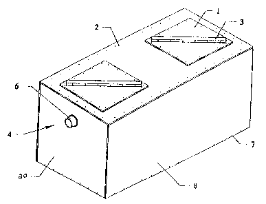
Figure 1 is a perspective view of one embodiment of the subject invention
assembled
septic tank kit.
Figures 2A-D are perspective views of the septic tank as;>embly of the subject
invention of Figure 1 with the tank lid and hatches shown off.
Figure 3 is a top view of a septic tank according to the subject invention.
Figure 4 is a side view of a septic tank according to the subject invention
Figure 5 is an end view of a septic tank according to the subject invention.
Figures 6A-F are open top views ofa septic tank according to the subject
invention.
Figures 7A-E are open-end views ofa septic tank according to the subject
invention.
Figure 8A-D are side views of the vertical section of a septic; tank according
to the
subject invention.
Figure 9 is a perspective exploded view of a septic tank kit according to the
subject
invention.
Figure 10 is a cross-sectional view of an embodiment of the double-channel
angle
connection bracket according to the subject invention.
Figure 11 is the cross-sectional view of the double-channel angle connection
bracket
depicted in Figure 10, but with modified reference points for additional
disclosure regarding
specific dimensions of one embodiment described herein.
S:\SH-APPS\hjp-I OSx2c2.canada.dociD~IB/s~p
CA 02432563 2003-06-17
S HJP~-lOSX2C2 CANADA
Figure 12 is a not-to-scale open top perspective view of an embodiment of a
septic
tank according to the subject invention which has a substantially trapezoidal
cross-sectional
appearance.
Figure 13 is a not-to-scale open top perspective view of an embodiment of a
septic
tank according to the subject invention which has a substantially trapezoidal
cross-sectional
appearance.
Figure 14 is a not-to-scale perspective view of an embodiment of a septic tank
according to the subject invention which has a substantially triangular cross-
sectional
appearance.
Figure 15 is a not-to-scale open top perspective view of an embodiment of a
septic
tank according to the subject invention which has a substantially triangular
cross-sectional
appearance.
Figure 16 depicts yet another alternative embodiment of a septic tank
according to
the subject invention which is substantially an inverted triangular-based
pyramid in
appearance, depicted with an open top.
Detailed Disclosure of the Invention
As shown in Figures 1 and 9, one embodiment of a septic tank according to the
subject invention comprises a tank lid 2, a tank bottom 18, a pair of opposing
side walls 8,
and a pair of opposing end walls 20, 21, an inlet end wall 20 and an outlet
end wall 21. The
tank lid 2 preferably comprises a pair of lid openings 16, which are covered
by hatch covers
1. The hatch covers 1 each comprise a hatch handle 3 for. ease of removal and
are removably
affixed to the tank lid 2 with angle alignment brackets 19 using, for example,
stainless steel
cap screws 7.
As shown in Figure 8, the outlet 21 and inlet end walls 20 comprise tank flow
outlet 4
and a tank flow inlet 5 respectively, where a flange 6 is affixed to each. of
the tank flow outlet
4 and tank flow inlet 5. The flange 6 is used to connect each of the flow
inlet 5 and flow
outlet 4 to the dwelling and drain field, respectively. Iru a preferred
embodiment, flanges 6
S:ISH-APPSIhjp-1 OSx2c2.canada.doc-,~DNB/srp
CA 02432563 2003-06-17
6 HJP-1O5X2C2 CANADA
can be plastic collars that are attached at tank flow outlet 4 and tatak flow
inlet S with a
deformable O-ring seal placed between the collar and the surface of the end
wall to provide a
flexible seal. In a particularly preferred embodiment, flanges 6 at tank flow
outlet 4 and tank
flow inlet 5 are made of a flexible plastic or rubber, which is deformable
while still
maintaining an effective seal. Especially preferred in this regard axe flanges
such as the
POLYLOK III, a septic tank seal available from Polylok, Inc., Yalesville,
Connecticut.
In an embodiment, as shown in Figures 6-9, the septic tank is assembled using
angle
connection brackets 11, which can be plastic or made of some other rr~aterial
rigid enough to
permit the assembled tank to retain its structural integrity (such as, for
example, stainless
steel), wherein the brackets 11 are affixed to the tank lid 2, tank botto:tn
18, side walls 8, and
end walls 20, 21 using, for example, stainless steel cap screws 7. A silicone
sealant 17 is
interposed between the tank lid 2, tank bottom 18, side walls 8, end walls 20,
ZI and the
connection brackets 11, forming a substantially leak proof sealing gasket.
Alternatively in
this and other embodiments of the tank, other sealants such as PERMATEX or GE
II silicone
rubber sealant could be used as will be readily apparent to the skilled
artisan. Further, the
angle connection brackets can optionally be provided with sealant material
prior to packaging
of the kit. In an embodiment, the sealant material can b~° of a
different color from the panels
which serve as tank walls, top, or bottom; and different from the color of the
connection
bracket; so that one can readily see that the sealant has been applied.
Alternatively, or in
addition to use of screws in assembly of this and other embodiments of the
tank, extrusion
welding can be used to connect and/or seal the various panels and other
plastic parts to each
other.
In an embodiment, the septic tank kit further comprises a baffle 10, wherein
the baffle
is positioned within the septic tank forming two compartments: an inlet
compartment 22
encompassing approximately 2/3 of the total volume of the tank, and a.n outlet
compartment
23. The baffle 10 presents a barrier which enables the larger sediment to
settle in the inlet
compartment 22, with the remaining effluent flowing into the outlet
compartment 23 through
the baffle port 12. Optionally, baffle 10 does not comprise a baffle port, in
which case the
baffle 10 should not extend completely from the tank bottom all the way to the
tank top so
S:1SH-APPS\hjp-tO5x2c2.canada.docil)NT3lsrp
CA 02432563 2003-06-17
7 HJP-1O5X2C2 CANADA
that flow from the inlet compartment 22 into the outlet compartment 23 is
accomplished over
the top of baffle 10.
In an embodiment, the septic tank kit further comprises a plurality of
structural
support members 13, wherein the structural support members :13 are vertically
and
horizontally affixed to the tank bottom 18, side walls 8, and end walls 20, 21
optionallyusing
a flange 6 at each attachment point. if flanges 6 are used to affix structural
support members,
then for this purpose it is generally preferred that they 'be of a relatively
rigid construction,
sufficiently rigid to ensure that the structural support members are affixed
in place.
In an alternative embodiment, the structural supports 13 are connected to the
tank
bottom 18, side walls 8, and end walls 20, 21 using angled connectors 15.
In an embodiment, as shown in Figure 9, the septic tank comprises two sets of
structural support members 13. The inlet compartment 22 comprises at least
three structural
supports 13, a vertical support member 24 interposed between the tank lid 2
and the tank
bottom 18, being connected to the tank bottom 18. The inlet compartment 22
further
comprises two horizontal support members 25, 26, wherein a first horizontal
support 25 is
connected to and interposed between the side walls 8, and a second horizontal
support 26 is
connected to and interposed between the inlet end wall 20 and the baffle 10.
The outlet
compartment 23 comprises at least one horizontal support 27, wherein the
horizontal support
27 is connected to and interposed between the outlet end wall 21 and the
baffle 10.
In an embodiment, the structural support members 13 are 3" diameter schedule
80
PVC pipe. Three different exemplary embodiments for common tank applications
are, for
example, %2" thick bottom, sides, and ends, with a'/4" thick lid; 5/g" thick
bottom, sides, and
ends, with a 3/4" thick lid; and 3/4" thick bottom, sides, ends, and lid.
Angle brackets in an
embodiment can be 2" x 2" x 0.2" right angles, and the fasteners can be, for
example,
stainless steel screws such as, for example, '/o" x 14 x 1 %4 " or '/o" x 14 x
1 '/2" hex head
screws. As the ordinary artisan will readily appreciate, the dimensions of the
panels, angles,
support members, and fasteners can be optimized for the particular task at
hand, considering
the strength of the materials involved. Preferably, for most standard septic
tank volumes, if
S:\SI~-APPSIhjp-1 OSx2c2.canada.doc/DNBlsrp
CA 02432563 2003-06-17
8 HJP-105X2C2 CANADA
the panels are made of copolymer polypropylene, they will be at least'/4"
thick and no more
than 4" thick, although depending on the volume of tank desired, it may be
optimal to have
panels with thicknesses outside of this range, as will be within the skill of
the ordinary artisan
to make such optimizations. As an example of the advantageous weight
characteristics of
septic tanks constructed in accord with the teachings herein, the following is
a Iist of
approximate weights of certain embodiments of tanks having various. volumes,
wherein the
tanks are made with bottoms, sides, and ends of %i" thick copolymer and lids
of 3/4" thick
copolymer:
Tank Volume in Gallons Approximate Weights (founds)
300 ~ 350 Ib~s.
750 ~ 625 lbs.
900 ~ 700 Ibs.
1050 750 lbs.
1200 ~ 810 lbs.
1500 ~ 950 Ibs.
The foregoing are merely intended to illustrate the advantageous weight
benefits of
the subject tanks (as compared to the much heaver prior art concrete tanks of
the same
volume). The weights can vary depending on a number of factors such as panel
thickness,
panel dimension, various associated hardware (such as some types of
fasteners), panel
composition, etc., as would be readily apparent to the; skilled artisan, and
still would be
within the scope of the subject invention.
In an embodiment, the septic tank lid 2, a tank bottom 18, a pair of opposing
side
walls 8, pair of opposing end walls 20, 21, and hatch covers 1 are made of
plastic that is
copolymer, or homopolymer.
In an embodiment, the septic tank lid 2 comprises only one opening.
In an embodiment, the tank flow inlet and tank flow outlet cyan be disposed in
the
S:\SH-APPS\hjp-l O5x2c2.canada.doc/DNB~srp
CA 02432563 2003-06-17
9 HJP-1O5X2C2 CANADA
same panel, preferably separated by a baffle.
In alternative embodiments, any hatch covers can be made of the same, or
different,
materials than the sides, ends, bottom, and lid.
Although septic tanks of the subject invention can be assemblf~d and then
transported
to the site of intended use for subsequent installation, in a method c>f use,
the septic tank,
which is available in kit form, is assembled at the work site. The septic tank
is transported to
the work site and assembled as follows:
In an embodiment, the end walls 20, 21 and side walls 8 are connected to the
tank
bottom 18 with the angle connection brackets 11, wherein the brackets 11 are
affixed using,
for example, stainless steel cap screws 7. Prior to assembly, a silicone
sealant 17 is
interposed between the tank bottom 18, side walls 8, and end walls 20., 21 and
the connection
brackets 11, forming a substantially leak proof seal to allow for proper
function of the septic
tank.
In a preferred embodiment, connection brackets 11 are in the form of double-
channel
angle brackets similar to that depicted in Figures 10 and 11. Referring to
Figure 10, the
double-channel angle bracket of the subject invention comprises a deep panel
receiving
channel 101 and a shallow panel receiving channel 102 defined by external
panel retaining
walls 107 and internal panel retaining walls 108. In the embodiment depicted
in Figure 10,
deep panel receiving channel 101 and shallow panel receiving channel 102 are
oriented
perpendicular to each other, for ease of assembling substantially flat, sheet
plastic panels into
a septic tank having two sides, two ends, a lid, and a bottom, for example
such as depicted in
Figures 1-9. Flat panels are preferred for use according to the teachings
herein, for ease of
packaging the kit and sealing the tank. However, as will be readily apparent
to the skilled
artisan, absolute flatness is not a requirement to practice the subject
invention. Preferably,
the panels of the bottom, sides, ends, and lid are substantially flat. A
"substantially" flat
panel is one which deviates from its plane by no more than d, where d2 =
(.0~)A, where A is
the area of the panel in square inches. The plane of the panel can be defined
by any 3 comers
of the panel. In a preferred embodiment, d2 = (.045)A; it is more preferred
that d2 = (.04)A; it
is still more preferred that d2 = {.035)A; even more preferred that d2 =
(.03)A; yet even more
S:1SH-APPSIhjp-1O5x2c2.canada.doc/DNF3/srp
CA 02432563 2003-06-17
HJP--1O5X2C2 CANADA
preferred that d2= (.025)A; particularlypreferred that d2= (.02)A; more
particularlypreferred
that d2 = (.015)A; and most preferred that d' _ (.0I )A.
In alternative embodiments of the septic tank of the subject: invention, the
angle
between the deep panel receiving channel and the shallow panel receiving
channel can be
either acute, or obtuse, as is required based on the intended ultimate
configuration of the
tank. For example, for the assembly of a tank having triangular side panels
assembled in
pyramidal form, all angles would be acute. See, for example, Figure 16.
Alternatively, tanks
having a substantially trapezoidal cross-sectional appearance would comprise
double-channel
angle brackets which in some cases possessed an acute angle between the deep
panel
receiving channel and the shallow panel receiving channel, and in other places
would require
an obtuse angle between the panel receiving channels, as would be readily
apparent to one of
ordinary skill in the art viewing the embodiments depicted in Figures 12 and
13. Other
embodiments, such as those having, for example, an octagonal cross-sectional
appearance,
would incorporate the use of double-channel angle brackets having
predominantly obtuse
angles between the receiving channels.
Returning to the embodiment depicted in Figure 10, at the closed end of each
receiving channel is preferably located a bottom stop 103 which is a slightly
raised portion
intended to prevent the edge of the inserted plastic panels from fully
contacting the bottom of
the panel receiving channels. Side stops 104 extend into the panel receiving
channels by
protruding from the inner surfaces of external panel retaining walls 107 and
from the inner
surfaces of internal panel retaining walls 108. Each side stop is defined in
part by sloped
panel accommodation surface 105 and sealant retaining surface 106. Each
sealant retaining
surface 106 is preferably substantially perpendicular to the internals surface
of the panel
retaining walls 107 and 108 to more effectively retain compressed sealant
within the interior
of each panel receiving channel. In operation, side stops 104 serve to assist
in centering the
panels in their respective panel receiving channels, and also to retain
sealant material
compressed within the panel receiving channels. In a method of use, sealant is
applied to the
bottom of a panel receiving channel. As the panel is inserted into the panel
receiving
channel, its leading edges may encounter the sloped panel accommodations
surfaces 105 of
S:1SH-APPS~hjp-l OSx2c2.canada.dociDNB/srp
CA 02432563 2003-06-17
11 HJP-1O5X2C2 CANADA
side stops 104. In a preferred embodiment, the sloped panel accommodation
surface is
angled so as to allow the leading edge of the panel to slide downward towards
the bottom of
the receiving channel. A panel is inserted fully into the channel, compressing
the sealant
until the panel contacts bottom stop 103. Sealant is forced up each side of
the panel
receiving channel and retained therein by sealant retaining surfaces 106 of
each side stop
I04.
As will be readily apparent to the ordinary skilled artisan, the panel
thickness can
vary depending on the size of the tank desired and the strength of the
materials from which
the panel is made, and the dimensions of the double-channel angle bracket
according to the
subject invention can be appropriately modified accordingly. However, for
illustrative
purposes, an example of a double-channel angle bracket depicted in Figure 11
has
dimensions which are suitable for accommodating panels of '/2 inch thickness,
and are as
follows:
AB and ST are S/8 inch
CD, EF, IJ, RS, and TU are '/4 inch
GH is 2'/8 inches
KL and V W are 1'/8 inch
MN is 1'/4 inch
PQ is %2 inch
QT and PS ',6 inch and
X is effectively a 90° angle causing deep panel receiving channel 101
and shallow
panel receiving channel 102 to be perpendicular, with the internal corner at X
effectively
rounded at '/4 inch radius.
In an embodiment, the double-channel angle connection brackets can be provided
with predrilled holes through which fasteners, such as stainless steel screws
or any other
fastener known to those of ordinary skill in the art which is effective for
assembling the tank,
S:\SH-APPS\hjp-l OSx2c2.canada.dociDNB/srp
CA 02432563 2003-06-17
12 HJP'-105X2C2 CANADA
can be inserted. In an alternative embodiment, the double-channel. angle
bracket can be
drilled at the site of assembly. Optionally, as provided in a kit according to
the subject
invention, the double-channel connection brackets can be premounted on one or
more of the
edges of one or more of the panels in the septic tank kit.
In an embodiment, a baffle 10 is positioned within the partially assembled
septic tank,
forming two compartments, an inlet compartment 22 and an outlet compartment
23, where
the inlet compartment 22 encompasses approximately 2/3 of the total volume of
the tank.
The baffle 10 presents a barner which enables the larger sediment to settle in
the inlet
compartment 22, with the remaining effluent flowing into the outlet
compartment 23 through
the baffle port 12.
In an embodiment, structural support members 13 are positioned within and
connected to the tank bottom 18, side walls 8, and end walls 20, 21. 7,he
inlet compartment
22 comprises at least three structural supports 13, a vertical support 24
interposed between
the tank lid 2 and the tank bottom 18, being connected to the tank bottom 18.
The inlet
compartment 22 further comprises two horizontal supports 25, 26, where a first
horizontal
support 25 is connected to and interposed between the side walls 8, and a
second horizontal
support 26 is connected to and interposed between the inlet end wall 20 and
the baffle 10.
The outlet compartment comprises at least one horizontal support 27, wherein
the horizontal
support 27 is connected to and interposed between the outlet end wall 21 and
the baffle 10.
The tank lid 2 is positioned on top of the partially assembled septic tank and
connected to the brackets 11 using fasteners, such as, for example, stainless
steel screws.
In an embodiment, the tank lid 2 comprises pre-drilled connection holes to
facilitate
attachment to the brackets 11.
In an embodiment, either or both of the tank lid 2 and tank bottom 18 can be
provided
in the kit with the connection brackets preattached to at least one edge
thereof. In a preferred
embodiment, double-channel angle connection brackets according to the subject
invention
are provided in the kit preattached to the edges of either or both of the tank
lid 2 and tank
bottom 18, preferably with the connection bracket affixed to the lid panel
such that the edge
S:\SH-APPS\hjp-l O5x2c2.canada.docIDNB,~srp
CA 02432563 2003-06-17
13 HJP-1O5X2C2 CANADA
of the lid panel is inserted into deep panel receiving channel 101 of each
double-channel
connection bracket affixed to its perimeter. Similarly, in an embodiment the
bottom panel
has double-channel connection brackets affixed thereto such that the panel
edges are inserted
into the deep panel receiving channel 101 of each double;-channel connection
bracket around
its periphery. In this embodiment, as the kit is unpacked and the tank is
assembled, the tank
bottom 18 having double-channel angle connection brackets preaffixed around
its periphery
will be configured such that side panels can be inserted into shallow panel
receiving channels
102 and then ultimately the tank lid, also having double-channel angle
connection brackets
affixed around its periphery can be lowered into place, with the to:p edges of
the panels
making up the side and end walls being inserted into the downward oriented
shallow panel
receiving channels 102 proj ecting perpendicularly downward from the periphery
of the tank
lid. Connection brackets are preferably used to connect the side walls to the
end walls along
the vertical edges where they meet. In a preferred embodiment, fasteners are
inserted
through the connection brackets and the panels contained therein to fasten the
walls, top, and
bottom of the tank in place. Extrusion welding can optionally replace or
augment the
brackets in connection of panels one to another.
The hatch covers 1 are positioned and connected to the tank lid 2 using
alignment
brackets 19 and appropriate fasteners, such as, for example, stainless steel
screws.
In an embodiment, the tank lid 2 and the hatch covers 1 comprise pre-drilled
connection holes to facilitate attachment to the alignment brackets 19.
In alternative embodiments, the septic tank kit can, upon assembly, yield
tanks of
various dimensions and configurations, as will be readily apparent to one of
ordinary skill in
the art in view of the teachings herein. For example, an alternative
embodiment is depicted
in Figure 12, wherein the assembled tank has a substantially trapezoidal cross-
section
appearance. Figure 12 depicts the tank without its lid, and without optional
internal supports,
being merely intended to illustrate the alternative configurations possible
using substantially
flat plastic panels in the kit of the subject invention. In Figure 12 are
depicted opposing side
walls 208, inlet end wall 220, outlet end wall 221, tank flow inlet 204, tank
flow outlet 205,
tank bottom 218, baffle Z 10, and baffle port 212.
S:1SH-APPS\hjp-l O5x2c2.canada.doc/DNB,~s~
CA 02432563 2003-06-17
14 HJP-1O5X2C2 CANADA
Referring to Figure 13, an alternative embodiment, also of substantially
trapezoidal
cross-sectional appearance, is depicted open top. This embodiment represents
an inversion
of the embodiment depicted in Figure 12, but having improved anti-buoyancy
characteristics
due to the increased surface area of the tank lid (not depicted) as compared
to the tank
bottom 318. In this embodiment are depicted inlet end wall 320, outlet end
wall 321, tank
flow inlet 304, tank flow outlet 30s, opposing side walls 308, baffle 310, and
baffle port 312.
Yet another alternative embodiment is depicted in Figure 14, wherein the
assembled
tank has a substantially triangular cross-sectional appearance. Represented in
Figure 14 are
tank inlet end wall 420, tank flow inlet 404, side walls 408, lid openings
416, baffle 410,
baffle port 412, tank outlet end wall 421, and tank flow outlet 405.
Turning now to Figure 15, yet another tank according to the subject invention
is
depicted which has a substantially triangular cross-sectional appearance, and
is shown open
top. As compared to the embodiment depicted in Figure 14, this embodiment has
improved
anti-buoyancy characteristics due to the substantial surface area of the tank
top (lid not
depicted), and the almost negligible surface area of the bottom, which is
formed at the vertex
of the meeting of side walls 508. Also represented in this figure are tank
inlet end wall 520,
tank flow inlet 504, tank outlet end wall 521, tank flow outlet 505, baffle
510, and baffle port
512.
Still another embodiment of a tank assembly provided in kit form according to
the
subject invention is depicted in Figure 16. This embodiment comprises a
minimum of four
substantially flat panels (if one excludes the optional baffle 610, which is
depicted in this
configuration). Represented in Figure 16 are three triangular shaped sidewalk
608, tank flow
inlet 604, tank flow outlet 605, optional baffle 610, and baffle port 612. Not
depicted is the
triangular shaped panel which would serve as a lid for this embodiment of the
tank.
Excluding the optional baffle, this embodiment of the tank comprises four
substantially flat
panels.
As is readily apparent to one of ordinary skill in the art in view of the
foregoing, a
wide variety of septic tank configurations can be provided in kit form
according to the
teachings herein.
S:~SH-APPSIhjp-l O5x2c2.canada.doc/DNBlsrp
CA 02432563 2003-06-17
15 HJP--1O5X2C2 CANADA
It should be understood that the examples and embodiments described herein are
for
illustrative purposes only and that various modifications or changes in light
thereof will be
suggested to persons skilled in the art and are to be included within the
spirit and purview of
this application.
S:\SH-APPSIhjp-I OSx2c2.canada.doclDNBlsrp