Language selection

Search

Patent 2432707 Summary

Third-party information liability

Some of the information on this Web page has been provided by external sources. The Government of Canada is not responsible for the accuracy, reliability or currency of the information supplied by external sources. Users wishing to rely upon this information should consult directly with the source of the information. Content provided by external sources is not subject to official languages, privacy and accessibility requirements.

Claims and Abstract availability

Any discrepancies in the text and image of the Claims and Abstract are due to differing posting times. Text of the Claims and Abstract are posted:

  • At the time the application is open to public inspection;
  • At the time of issue of the patent (grant).
(12) Patent: (11) CA 2432707
(54) English Title: LAYING HEAD FOR ROD ROLLING MILL
(54) French Title: TETE DE POSE POUR LAMINOIR A FIL-MACHINE
Status: Deemed expired
Bibliographic Data
(51) International Patent Classification (IPC):
  • B02C 15/06 (2006.01)
  • B02C 23/00 (2006.01)
  • B21C 47/14 (2006.01)
(72) Inventors :
  • SHORE, T. MICHAEL (United States of America)
  • SHEN, WILLIAM X. (United States of America)
  • ZHANG, PEILIANG L. (United States of America)
(73) Owners :
  • SIEMENS INDUSTRY, INC. (United States of America)
(71) Applicants :
  • MORGAN CONSTRUCTION COMPANY (United States of America)
(74) Agent: FETHERSTONHAUGH & CO.
(74) Associate agent:
(45) Issued: 2007-11-20
(22) Filed Date: 2003-06-18
(41) Open to Public Inspection: 2003-12-19
Examination requested: 2003-06-18
Availability of licence: N/A
(25) Language of filing: English

Patent Cooperation Treaty (PCT): No

(30) Application Priority Data:
Application No. Country/Territory Date
60/389,786 United States of America 2002-06-19
10/457,274 United States of America 2003-06-09

Abstracts

English Abstract

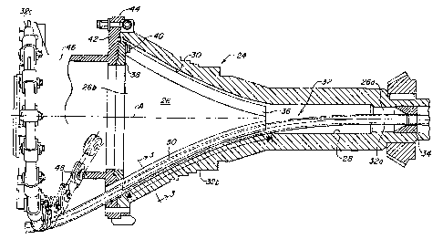
In a laying head for forming a longitudinally moving hot rolled product into a helix, a laying pipe is received in a central passageway extending through a rotatable quill. The interior surface of a flared section of the central passageway is configured to conform to and to radially inwardly confine a curved intermediate portion of the laying pipe.


French Abstract

Dans une tête de pose pour former en hélice un produit laminé à chaud se déplaçant longitudinalement, un tuyau de pose est reçu dans un passage central s'étendant à travers un fourreau rotatif. La surface intérieure d'une section évasée de la voie de passage centrale est configurée pour se conformer à, et à confiner radialement vers l'intérieur une partie incurvée intermédiaire du tuyau de pose.

Claims

Note: Claims are shown in the official language in which they were submitted.


WE CLAIM:


1. A laying head for forming a longitudinally moving hot rolled product into a

helix, said laying head comprising:

a tubular quill having a central axis of rotation and an interior surface
surrounding a
passageway extending along said axis and through said quill from a first end
to an opposite
second end, said interior surface having a cylindrical section leading from
said first end to a
radially outwardly flared section which in turn leads to said second end;

a laying pipe received in said passageway, said laying pipe having an entry
end
aligned with said axis at the first end of said passageway, and having a
curved intermediate
portion surrounded by the flared section of the interior quill surface, said
laying pipe
projecting axially from the second end of said passageway to a delivery end
spaced radially
from said axis;

first support means at the first end of said passageway for radially
supporting the
entry end of said laying pipe; and

second support means for supporting the curved intermediate portion of said
laying
pipe, said second support means projecting axially into said passageway from
the second end
thereof.


2. The laying head as claimed in claim 1 wherein said second support
means is configured and dimensioned to confine the intermediate portion of
said laying
pipe against the flared section of the interior surface of said quill.


4


3. The laying head of claims 1 or 2 further comprising a circular collar
detachably secured to said quill at the second end of said passageway, said
second support
means being carried by and projecting axially from said collar into said
passageway.


4. A laying head for forming a longitudinally moving hot rolled product into a

helix, said laying head comprising:

a tubular quill having a central axis of rotation and an interior surface
surrounding a
passageway extending along said axis and through said quill from a first end
to an opposite
second end, said interior surface having a radially outwardly flared section
adjacent to said
second end;

a laying pipe received in said passageway, said laying pipe having an entry
end
aligned with said axis at the first end of said passageway, and having a
curved intermediate
portion surrounded by the flared section of the interior quill surface, said
laying pipe
projecting axially from the second end of said passageway to a delivery end
spaced radially
from said axis;

first support means at the first end of said passageway for radially
supporting the
entry end of said laying pipe; and

second support means axially received in the second end of said passageway,
said
second support means being configured and dimensioned to support the curved
intermediate
portion of said laying pipe.


5. The laying head of claim 4 wherein the flared section of the interior
surface of
said quill is configured to conform to and to radially inwardly confine the
curved


5


intermediate portion of said laying pipe, and wherein said second support
means is
configured and dimensioned to outwardly confine the curved intermediate
portion of said
laying pipe against said flared section.


6

Description

Note: Descriptions are shown in the official language in which they were submitted.


CA 02432707 2004-07-30

LAYING HEAD FOR ROD ROLLING MILL
BACKGROUND DISCUSSION

1. Field of the Invention

This invention relates generally to laying heads for rod rolling mills, and is
concerned
in particular with an improvement in the manner in which the laying pipes are
supported
within the laying heads.

2. Descrintion of the Prior Art

Figure 1 depicts a conventional laying head having a tubular quill 10
supported
between bearings (not shown) for rotation about an axis A. A laying pipe 12
has an entry end
12a aligned with the axis A for receiving hot rolled rod from the last roll
stand of the mill. A
three dimensionally curved intermediate portion 12b leads from the entry end
12a of the pipe
to a delivery end 12c from which the rod is delivered as a helical formation
of rings.

The outboard portion of the pipe projecting beyond the quill 10 is radially
and axially
supported by a series of clamps 14 carried on arranger plate 16 projecting
from a tubular boss
18. However, the pipe portion contained within the quill is supported only
radially at 20.
During high speed operation of the laying head, the pipe portion within the
quill is thus
relatively free to deflect, causing accelerated wear in the region 22.
Deflection is occasioned
by centrifugal forces, and thermal expansion.


SUMMARY OF THE INVENTION

In accordance with the present invention, there is provided a laying head for
forming
a longitudinally moving hot rolled product into a helix, said laying head
comprising

1


CA 02432707 2004-07-30

a tubular quill having a central axis of rotation and an interior surface
surrounding a
passageway extending along said axis and through said quill from a first end
to an opposite
second end, said interior surface having a cylindrical section leading from
said first end to a
radially outwardly flared section which in turn leads to said second end; a
laying pipe

received in said passageway, said laying pipe having an entry end aligned with
said axis at
the first end of said passageway, and having a curved intermediate portion
surrounded by the
flared section of the interior quill surface, said laying pipe projecting
axially from the second
end of said passageway to a delivery end spaced radially from said axis; first
support means
at the first end of said passageway for radially supporting the entry end of
said laying pipe;

and second support means for supporting the curved intermediate portion of
said laying pipe,
said second support means projecting axially into said passageway from the
second end
thereof.

The invention also provides a laying head for forming a longitudinally moving
hot
rolled product into a helix, said laying head comprising a tubular quill
having a central axis of
rotation and an interior surface surrounding a passageway extending along said
axis and

through said quill from a first end to an opposite second end, said interior
surface having a
radially outwardly flared section adjacent to said second end; a laying pipe
received in said
passageway, said laying pipe having an entry end aligned with said axis at the
first end of
said passageway, and having a curved intermediate portion surrounded by the
flared section

of the interior quill surface, said laying pipe projecting axially from the
second end of said
passageway to a delivery end spaced radially from said axis; first support
means at the first
end of said passageway for radially supporting the entry end of said laying
pipe; and second
support means axially received in the second end of said passageway, said
second support

2


CA 02432707 2004-07-30

means being configured and dimensioned to support the curved intermediate
portion of said
laying pipe.

Preferably, an internal pipe support is axially received in the quill and is
configured
and dimensioned to confme the curved intermediate pipe portion against the
conformed

interior quill surface.

These and other features and advantages of the present invention will now be
described in greater detail with reference to the accompanying drawings,
wherein:
BRIEF DESCRIPTION OF THE DRAWINGS

Figure 1 is a longitudinal sectional view taken through a prior art quill and
laying pipe
assembly;

Figure 2 is a sectional view similar to Figure 1 showing a quill and laying
pipe
assembly in accordance with the present invention; and

Figure 3 is a sectional view on an enlarged scale taken along line 3-3 of
Figure 2.

DETAILED DESCRIPTION OF PREFERRED EMBODIMENT

In accordance with the present invention, and as shown in Figures 2 and 3, the
tubular
quill 24 has a central axis of rotation A and an interior surface surrounding
a passageway 26
extending along axis A from a first end 26a to an opposite second end 26b. The
interior

surface has a stepped cylindrical section 28 leading from the first end 26a of
the passageway
26

2(a)


CA 02432707 2003-06-18

D-1198
to a radially outwardly flared section 30 which in turn leads to the second
end 26b of the

passageway.
A laying pipe 32 is received in the passageway 26. The laying pipe has an
entry end
32a aligned with axis A at the first passageway end 26a, and a three
d'nnensionally curved

intermediate portion 32b surrounded by the flared section 30 of the interior
quill surface. The
laying pipe projects axially from the second passageway end 26b to a delivery
end 32c spaced
radially from axis A.

The flared section 30 of the interior quill surface is configured to conform
to and to
radially inwardly confine the curved intermediate pipe portion 32b. A support
means in the
form of an annular insert 34 is received in the first end 26a of the
passage;way 26 to radially
support the entry end 32a of the laying pipe 32.

Preferably, an internal pipe support 36 is axially received in the second end
26b of the
passageway 26. The pipe support has an end flange 38 secured as at 40 to a
collar 42
removably secured to the quill 24 by swing bolts 44 (only one being shown).
Collar 42

supports a tubular boss 46 carrying brackets 48 for the axially projecting
portion of the laying
pipe 32.

The pipe support 36 has a peripheral three dimensionally curved track 50
configured
and dimensioned to confme the intermediate pipe portion 32b against the
complimentary
shaped flared section 30 of the interior quill surface.

By thus closely confining the curved intermediate pipe portion 32b, deflection
that
might otherwise occur due to centrifugal forces and thermal expansion is thus
beneficially
reduced, with a concomitant reduction in wear of the laying pipe.

3

Representative Drawing
A single figure which represents the drawing illustrating the invention.
Administrative Status

For a clearer understanding of the status of the application/patent presented on this page, the site Disclaimer , as well as the definitions for Patent , Administrative Status , Maintenance Fee  and Payment History  should be consulted.

Administrative Status

Title Date
Forecasted Issue Date 2007-11-20
(22) Filed 2003-06-18
Examination Requested 2003-06-18
(41) Open to Public Inspection 2003-12-19
(45) Issued 2007-11-20
Deemed Expired 2015-06-18

Abandonment History

There is no abandonment history.

Payment History

Fee Type Anniversary Year Due Date Amount Paid Paid Date
Request for Examination $400.00 2003-06-18
Application Fee $300.00 2003-06-18
Registration of a document - section 124 $100.00 2003-08-05
Maintenance Fee - Application - New Act 2 2005-06-20 $100.00 2005-06-07
Maintenance Fee - Application - New Act 3 2006-06-19 $100.00 2006-05-24
Maintenance Fee - Application - New Act 4 2007-06-18 $100.00 2007-05-16
Final Fee $300.00 2007-09-07
Maintenance Fee - Patent - New Act 5 2008-06-18 $200.00 2008-05-30
Maintenance Fee - Patent - New Act 6 2009-06-18 $200.00 2009-05-12
Maintenance Fee - Patent - New Act 7 2010-06-18 $200.00 2010-05-25
Registration of a document - section 124 $100.00 2010-07-13
Maintenance Fee - Patent - New Act 8 2011-06-20 $200.00 2011-05-11
Maintenance Fee - Patent - New Act 9 2012-06-18 $200.00 2012-05-04
Maintenance Fee - Patent - New Act 10 2013-06-18 $250.00 2013-05-06
Owners on Record

Note: Records showing the ownership history in alphabetical order.

Current Owners on Record
SIEMENS INDUSTRY, INC.
Past Owners on Record
MORGAN CONSTRUCTION COMPANY
SHEN, WILLIAM X.
SHORE, T. MICHAEL
ZHANG, PEILIANG L.
Past Owners that do not appear in the "Owners on Record" listing will appear in other documentation within the application.
Documents

To view selected files, please enter reCAPTCHA code :


To view images, click a link in the Document Description column. To download the documents, select one or more checkboxes in the first column and then click the "Download Selected in PDF format (Zip Archive)" or the "Download Selected as Single PDF" button.

List of published and non-published patent-specific documents on the CPD .

If you have any difficulty accessing content, you can call the Client Service Centre at 1-866-997-1936 or send them an e-mail at CIPO Client Service Centre.


Document
Description 
Date
(yyyy-mm-dd) 
Number of pages   Size of Image (KB) 
Claims 2006-05-29 3 75
Abstract 2003-06-18 1 13
Description 2003-06-18 3 136
Claims 2003-06-18 3 95
Drawings 2003-06-18 2 92
Representative Drawing 2003-08-26 1 28
Cover Page 2003-11-21 1 52
Claims 2004-07-30 3 77
Description 2004-07-30 4 159
Cover Page 2007-10-24 1 54
Prosecution-Amendment 2006-05-29 5 150
Fees 2005-06-07 1 38
Correspondence 2003-07-24 1 30
Assignment 2003-06-18 2 102
Assignment 2003-08-05 3 110
Correspondence 2003-08-29 1 32
Correspondence 2003-09-26 1 11
Prosecution-Amendment 2004-07-30 8 224
Prosecution-Amendment 2005-11-29 2 59
Correspondence 2007-09-07 1 38
Correspondence 2008-01-21 1 14
Correspondence 2008-02-22 1 12
Correspondence 2008-01-29 2 52
Assignment 2010-07-13 11 330
Examiner Requisition 2003-08-29 1 33